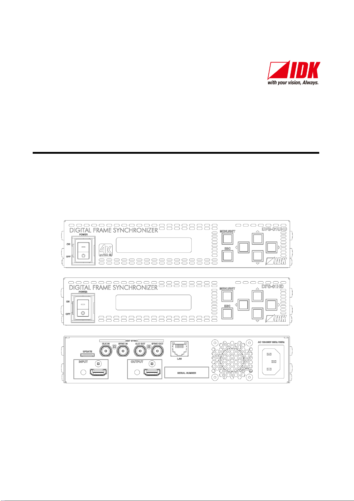
DFS-01UHD / DFS-01HD Command Guide
4
Table of Contents
1About this Guide................................................................................................................................... 5
2Communication configuration and Specifications .................................................................................. 6
2.1 LAN communication ........................................................................................................................ 6
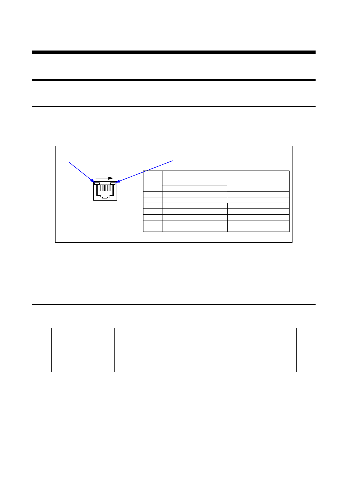
2.1.1 LAN connector specification..................................................................................................... 6
2.1.2 LAN communication specification............................................................................................. 6
2.1.3 Setting up LAN communication................................................................................................. 7
2.1.4 The number of TCP-IP connections.......................................................................................... 8
3Command ............................................................................................................................................ 9
3.1 Command outline............................................................................................................................ 9
3.2 Command list .................................................................................................................................10
3.3 Detailed descriptions......................................................................................................................12
3.3.1 Error status.............................................................................................................................12
3.3.2 Output timing...........................................................................................................................13
3.3.3 Output setting..........................................................................................................................17
3.3.4 Input timing.............................................................................................................................20
3.3.5 Input setting............................................................................................................................26
3.3.6 Videowall setting.....................................................................................................................27
3.3.7 Audio......................................................................................................................................28
3.3.8 EDID setting............................................................................................................................31
3.3.9 LAN communication................................................................................................................35
3.3.10 Preset memory........................................................................................................................37
3.3.11 Other settings..........................................................................................................................38