IDS GeoRadar IBIS KU ETH User manual
Mod: MDM/011/M4 Rev 1
IDS GeoRadar User Guide QGG/2021/001 Rev. 1.4
IBIS KU ETH
User Guide
October 2021
Mod: MDM/011/M4 Rev 2
IDS GeoRadar User Guide QGG/2021/001 Rev. 1.4
1. Important Information about your Instrument
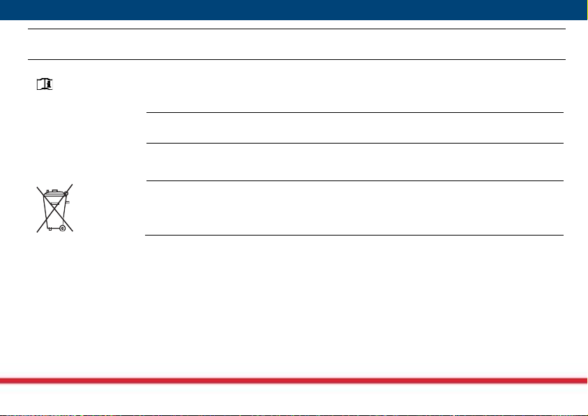
Read and follow the User Manual before using the product or the accessories delivered
with the product.
☞
Keep for future reference!
Intended use
Radar sensor used in several IDSGeoradar products with the main purpose of performs
remote displacements monitoring of structure and land.
The product must not be disposed with household waste.

Mod: MDM/011/M4 Rev 2
IDS GeoRadar User Guide QGG/2021/001 Rev. 1.4
Conformity to
European
regulations
The equipment is in compliance with the essential requirements and other relevant
provisions of Directive 2014/53/UE.
The full Declaration of its Conformity is sent separately together with the shipping
documents of the product.
This equipment is destined for use in industrial environments (Class A apparatus). In
residential, commercial and light industry environments, this apparatus may generate radio
interference: in this case, the user may need to take adequate measures
Conformity to
U.S regulations.
FCC Use limits
The IBIS KU ETH sensor is granted by FCC approved, according to the Code of Federal
Regulations, Title 47, Chapter I, Subchapter D, part 90, Subpart F, Private land mobile radio
services; Radiolocation Service. In order to use the sensor in the US territory, a license of
utilization must be obtained by FCC.FCC Statements:
- Operation is subject to the following two conditions: (1) this device may not cause
interference, and (2) this device must accept any interference, including interference that
may cause undesired operation of the device.
- Changes or modifications not expressly approved by the party responsible for
compliance could void the user's authority to operate the equipment.
- This product complies with FCC and ISED radiation exposure limits set forth for an
uncontrolled environment. The antenna should be installed and operated with minimum
distance of 26 cm between the radiator and your body.
Mod: MDM/011/M4 Rev 2
IDS GeoRadar User Guide QGG/2021/001 Rev. 1.4
This product poses no health and safety risk when operated in the normal manner of the
intended use.
Conformity to
Canada
regulations.
The IBIS KU ETH sensor is granted by ISED as a license exempt low power device, according
to RSS-210 Issue 10, Annex B, B.11. Within the above mentioned limitation in terms of band
and emitted power, IBIS KU ETH can be used in Canada, without any license.
For more information about licensing procedure contact IDS GeoRadar personnel.
ISED Statements:
. This device complies with Health Canada's Safety Code. The installer of this device should
ensure that RF radiation is not emitted in excess of the Health Canada's requirement.
Information can be obtained at http://www.hc-sc.gc.ca/ewh-
semt/pubs/radiation/radio_guide-lignes_direct-eng.php.
. Cet appareil est conforme avec SantCanada Code de scurit6. Le programme
d'installation de cet appareil doit s'assurer que les rayonnements RF n'est pas mis au-del
de I'exigence de SantCanada. Les informations peuvent tre obtenues: http://www.hc-
sc.gc.ca/ewh-semt/pubs/radiation/radio_guide-lignes_direct-eng.php
. Les changements ou modifications non expressment approuvs par la partie
responsable de la conformitpourraient annuler l'autoritde l'utilisateur utiliser cet
quipement.

Mod: MDM/011/M4 Rev 2
IDS GeoRadar User Guide QGG/2021/001 Rev. 1.4
. This device contains license-exempt transmitter(s)/receiver(s) thatcomply with Innovation,
Science and Economic Development Canada's license-exempt RSS(s). Operation is subject to
the following two conditions:
1. This device may not cause interference.
2. This device must accept any interference, including interference that may cause
undesired operation of the device.
. L'metteur/rcepteur exempt de licence contenu dans le prsent appareil est conforme aux
CNR d'Innovation, Sciences et Dveloppement conomique Canada applicables aux appareils
radio exempts de licence. L'exploitation est autorise aux deux conditions suivantes:
1. L'appareil ne doit pas produire de brouillage;
2. L'appareil doit accepter tout brouillage radiolectrique subi, mme si le brouillage est
susceptible d'en compromettre le fonctionnement.
. Cet appareil est conforme aux limites d'exposition aux rayonnements de l’ISED pour un
environnement non contrôlé. L'antenne doit être installé de façon à garder une distance
minimale de 26 centimètres entre la source de rayonnements et votre corps.

Mod: MDM/011/M4 Rev 2
IDS GeoRadar User Guide QGG/2021/001 Rev. 1.4
Canadian Representative:
Company Name: Leica Geosystems Ltd
Company Number: 3177B
Company Address: 1-3761 Victoria Park Ave
City: Scarborough
Province/State: Ontario
Postal Code: M1W 3S2
Country: Canada
Contact Name: Sudha Sachdeva
Phone Number: +1 416 497 2463
Mod: MDM/011/M4 Rev 2
IDS GeoRadar User Guide QGG/2021/001 Rev. 1.4
1.1 Symbols
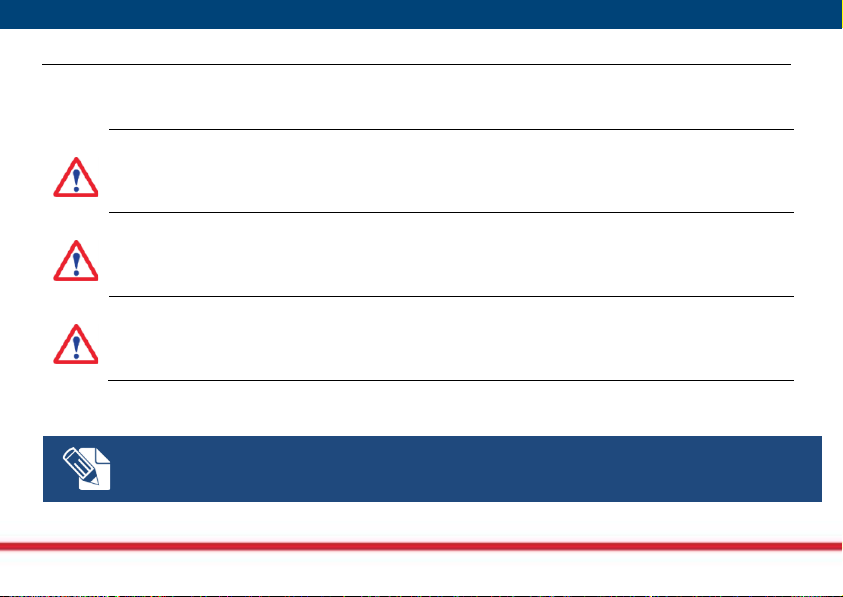
Warning messages are an essential part of the Safety Concept of the instrument. They appear wherever hazards or
hazardous situations can occur.
WARNING
Indicates an imminently hazardous situation which, if not avoided, will result in death or serious
injury.
DANGER
Indicates a potentially hazardous situation or an unintended use which, if not avoided, could result in
death or serious injury.
CAUTION
Indicates a potentially hazardous situation or an unintended use which, if not avoided, may result in
minor or moderate injury.
Supplementary safety information may be placed as notice message with the symbol indicated below.
Note text/to keep in mind.

Mod: MDM/011/M4 Rev 2
IDS GeoRadar User Guide QGG/2021/001 Rev. 1.4
2.
Hazard of use
NOTICE: Watch out for erroneous measurement results if the product has been dropped or has been
misused, modified, stored for long periods or transported.
Precautions:
Periodically carry out test measurements and perform the field adjustments indicated in the user
manual, particularly after the product has been subjected to abnormal use and before and after
important measurements.
NOTICE: Only IDS GeoRadar authorized technical service are entitled to repair this product.
DANGER
Improper use of the sensor can, unforeseen installation can create dangers if the user does not pay
attention to the recommendations given in the user manual of the system in which the sensor is used
Precautions

Mod: MDM/011/M4 Rev 2
IDS GeoRadar User Guide QGG/2021/001 Rev. 1.4
Before carrying out any operation on the sensor, follow the instructions given in the user manual of the
system to which it belongs.
DANGER
During the transport, unpackage or setup of the sensor on the system user must be aware of the
dangers associated with the possible fall of the sensor
Precautions
Before carrying out any operation on the sensor, follow the instructions given in the user manual of the
system to which it belongs.
DANGER
During surveys there is a danger of accidents occurring if the user does not pay attention to the
environmental conditions around, for example obstacles, excavations or traffic.
Precautions
During operations, the user of the product must be fully aware of the existing dangers.
DANGER
IBIS KU ETH when operates emits non-ionizing radiations that can cause interference with implanted
electrical or ferromagnetic devices (such as a pacemaker).
Mod: MDM/011/M4 Rev 2
IDS GeoRadar User Guide QGG/2021/001 Rev. 1.4
DANGER
The use of the sensor in explosive environments such as gassy mines is strictly forbidden. The non-
ionizing radiations can interfere with devices such as detonators and cause explosions.
DANGER
During themaintenance ofthe system always switch off thesystem and disconnect it from the power
source.
DANGER
Always perform the maintenance and regulation of the system with steady Acquisition Unit.
Performing these operations with the system moving can cause hazards.

Mod: MDM/011/M4 Rev 2
IDS GeoRadar User Guide QGG/2021/001 Rev. 1.4
3.
Product Components
IBIS KU ETH is basically a radar sensor with range distance measure capabilities and give the possibility, with
interferometric technique, to measure the displacement information from the phase variation of the backscattered
signals from the area of interest thanks to its phase stability. The IBIS KU ETH is the radiating element used in the
following IDS Georadar products:
•IBIS ARCSAR
•IBIS FM EVO
•IBIS FS/FB
These products are particularly suitable for terrain and structural monitoring applications by a capability of measure
slow displacement at an accuracy great as a tenth of a millimeter, the overall performance dependes on the type of
system in which the sensor is installed.

Mod: MDM/011/M4 Rev 2
IDS GeoRadar User Guide QGG/2021/001 Rev. 1.4
3.1
General descripti
on
The sensor is a yellow box present in two configurations depending on the destination product:
•Standard configuration (two antennas –1 Transmitting antenna, 1 Receiving antenna)
•MIMO configuration with DEM KIT (four antennas –2 Transmitting antenna, 2 Receiving antenna)
Fig. 1 –IBIS KU ETH sensor
Mod: MDM/011/M4 Rev 2
IDS GeoRadar User Guide QGG/2021/001 Rev. 1.4
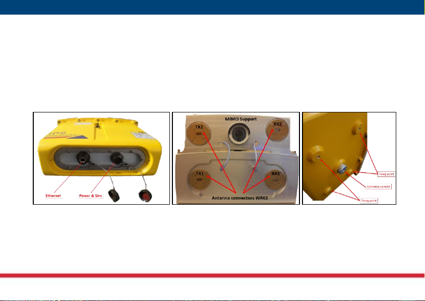
The unit contain all the parts for the generation, transmission, reception and acquisition of the radar signal. It
features the following interfaces:
•
1 - ETH RJ45 connector
on the rear of the box;
•
1 - 23 pole Male connector
to provide power and sync. On the rear of the box;
•
2 - waveguide WR62 (4 - in MIMO configuration)
for the antennas on the front of the box
•
4 - fixing point (M5)
on the bottom of the box
•
1 - central point
that it is used to fix the centering cylinder or the hexagonal head for the tripod
Fig. 2 –IBIS KU ETH rear, front and bottom view

Mod: MDM/011/M4 Rev 2
IDS GeoRadar User Guide QGG/2021/001 Rev. 1.4
The operations to be performed on the sensor for installation on the system will be:
•
Fixing to the system using the appropriate fixing points
•
Connection to the multipolar connector of the power and sync. cable present on the system
•
Connection to the RJ45 Ethernet connector of the data cable present on the system
The sensors is delivered typically with antennas mounted, otherwise connect the antennas to the waveguides
using appropriate screws.
Fig. 3 –Example of antennas with screw
The operations of installation must follow the procedures reported in the system user manual.
Mod: MDM/011/M4 Rev 2
IDS GeoRadar User Guide QGG/2021/001 Rev. 1.4
3.2
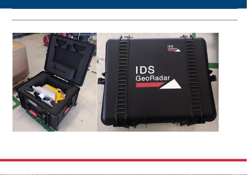
How the sensor is deliverd
The sensor is delivered inside a peli case.
Fig. 4 –IBIS KU ETH case

Mod: MDM/011/M4 Rev 2
IDS GeoRadar User Guide QGG/2021/001 Rev. 1.4
4.
Installation Procedure
DANGER
For the sensor installation procedure follow the instructions given in the system user manual
Mod: MDM/011/M4 Rev 2
IDS GeoRadar User Guide QGG/2021/001 Rev. 1.4
5.
Switching the system ON/OFF
DANGER
Do not power the sensor with sources other than the systems supplied by IDSGeoradar. Follow the
instructions given in the system user manual

Mod: MDM/011/M4 Rev 2
IDS GeoRadar User Guide QGG/2021/001 Rev. 1.4
6.
Technical Specifications
6.1
Sensor specifications
Parameter
Value
Temperature range
-40 °C ÷ +55 °C
Encloser Class
IP65
Dimension
Standard version 40 cm x 17 cm x 29 cm
MIMO version 40 cm x 28 cm x 29 cm
Weight
Standard version 11 Kg
MIMO version 12 Kg
Input voltage range
12 V DC –24 V DC
Power Consumption
Standard 27W
MIMO 30W
Table 1 –Environmental specifications

Mod: MDM/011/M4 Rev 2
IDS GeoRadar User Guide QGG/2021/001 Rev. 1.4
Parameter
Value
Operating Range
50m –5000m
RF operating band
EU:17.1 –17.3 GHz
USA: 17.1 –17.3 GHz
Canada: 17.1–17.3 GHz
Emission bandwidth
EU/USA 200 MHz
Canada 200 MHz
Maximum power at the
antenna connector
It dependes on the regulation and on the antenna
installed
Antenna Type
Horn
Antenna Gain
See Table 3
Max Equivalent Isotropic
Radiated Power (EIRP)
EU: 26 dBm
USA: 36 dBm
Canada: 24.7 dBm
Signal modulation
FMCW
Certifications
CE, FCC, ISED
Table 2 - IBIS KU ETH radio specifications.
Mod: MDM/011/M4 Rev 2
IDS GeoRadar User Guide QGG/2021/001 Rev. 1.4
6.2
Antenna specifications
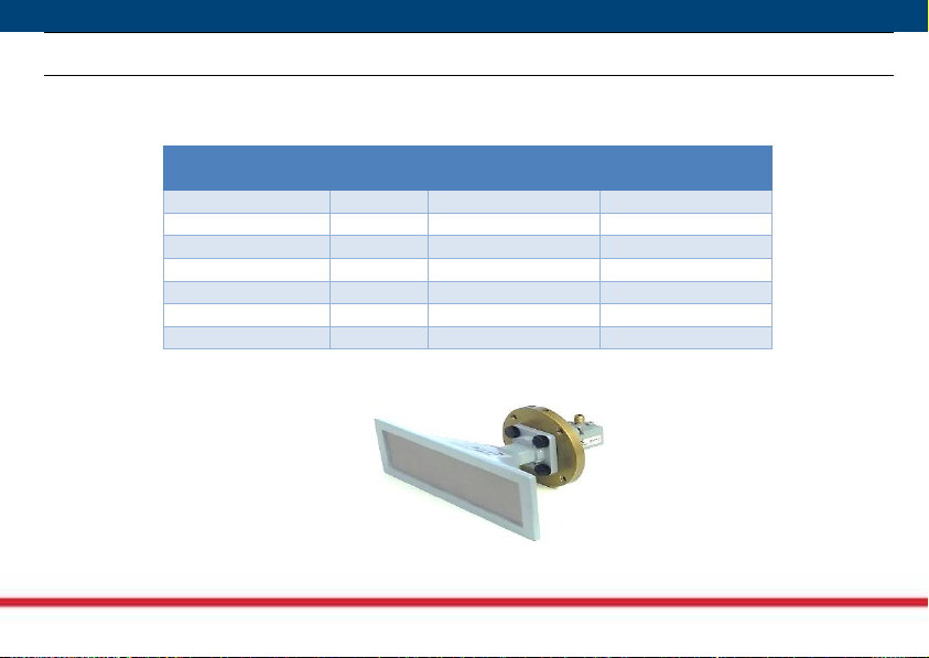
The sensor mount horn antennas type. It is typically supplied with IBIS-ANT7-H50V31 antenna type but for
particular applications it can mount different antenna types.
Antenna Type
Gain [dB]
Azimuth
Beamwidth (-3dB)
Elevation
Beamwidth (-3dB)
IBIS-ANT1-H38V18
15
38
18
IBIS-ANT2-H29V25
14
29
25
IBIS-ANT3-H17V15
19
17
15
IBIS-ANT4-H11V10
22
11
10
IBIS-ANT5-H12V39
18
12
39
IBIS-ANT6-H51V20
14
50
20
IBIS-ANT7-H50V31
13.5
50
31
Table 3 –IBIS KU ETH horn antennas.
Fig. 5 –IBIS-ANT7-H50V31 Antenna
Table of contents
Popular Accessories manuals by other brands


Daintree
Daintree GE Current WOS2-CM installation guide

Orno
Orno OR-CR-206 instructions

Keli Sensing Technology
Keli Sensing Technology D2008type user manual

Velleman
Velleman K8067 Illustrated assembly manual

Nexmosphere
Nexmosphere XF-P3W product manual

Byron
Byron B314 Installation and operation instruction