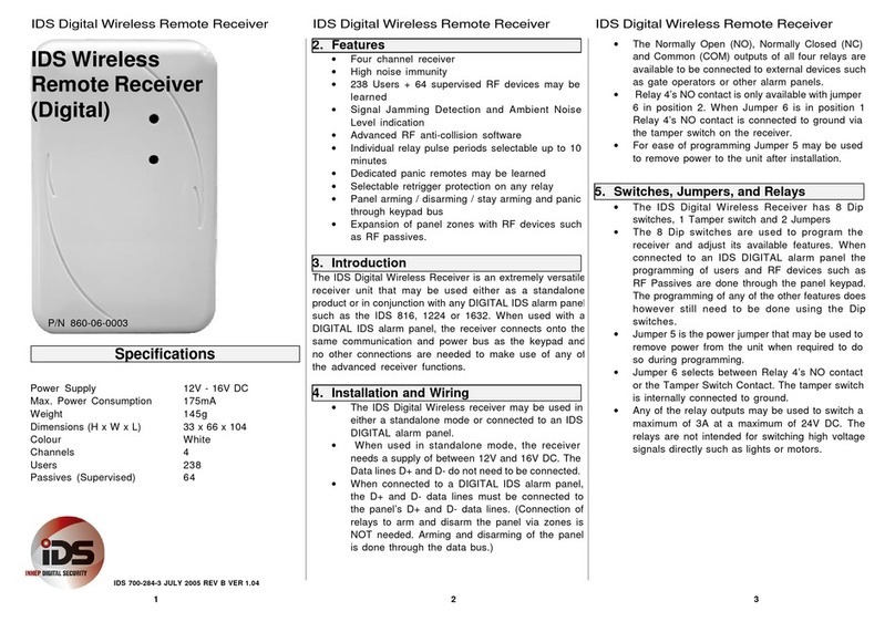
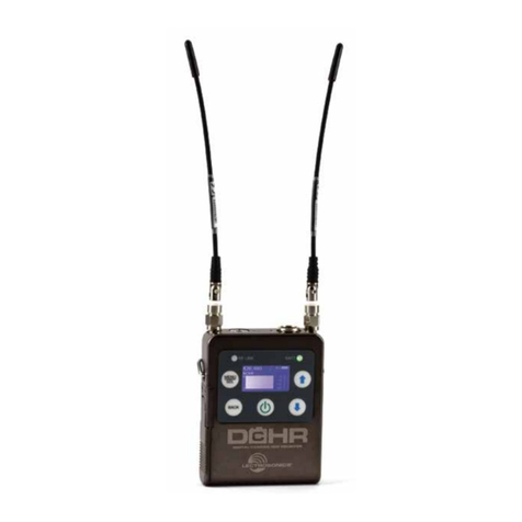
IDS 860-06-0004 User manual

ID
S
Key
p
a
d
Bu
s
Remot
e
Receive
r
ID
S
Key
p
a
d
Bu
s
Remot
e
Receive
r
ID
S
Key
p
a
d
Bu
s
Remot
e
Receiver
ID
S
Key
p
ad
Bus
Remote Receiver
(Digital
-
No
Relays)
2
.
F
ea
t
u
r
e
s
•Four channel receiver
•High noise immunity
•238 Users +64 supervised RF devices may
be
learned
•Signal Jamming Detection and Ambient
Noise
Level indication
•Advanced RF anti-collision software
•Panel arming /disarming /stay arming and panic
through keypad bus
•Expansion of panel zones with RF devices
such
6
.
R
F
Passive
s
ar
e
don
e
throug
h
th
e
p
ane
l
key
p
ad.
The programming of any of the other features
does
however still need to be done using the
Dip
switches.
•Jumper 5is the power jumper that may be used to
remove power from the unit when required to do
so during programming.
Programming
the
Unit
in
Stand
-
Alone
Mode.
(Power
Up
Settings)
3
.
a
s
R
F
p
assives.
Introduction
N.B
.
t
o
chang
e
an
y
setting
s
o
n
th
e
receive
r
unit
,
the
receiver needs to be powered down, the
settings
changed and then powered up again.
P/N
860
-
06
-
0004
The
IDS
Digi
t
a
l
Wireless
Receiver
is
an
extremely
versatile
receiver unit that may be used in conjunction with any
DIGITAL IDS alarm panel such as the IDS 816, 1224 or
1632. When used with aDIGITAL IDS alarm panel,
the
receiver connects onto the same communication and
power
bus as the keypad and no other connections are
needed
to
make
use
of
any
of
the
advanced
receiver
functions.
R
es
t
o
r
i
n
g
t
h
e
F
a
c
t
o
r
y
D
e
f
a
u
l
t
S
e
tt
i
ng
s
:
1. Remove power from the unit by removing
jumper
J1 and switch all Dip switches OFF.
2. Switch Dip switches 1, 5, 6, 7and 8ON
3. Restore Power to the Unit by replacing J1
4. Switch Dip Switch 8OFF
5. Wait for the LED’s to start flashing alternately.
Specifications
Power Supply 12V -16V DC
Max. Power Consumption 175mA
Weight 145g
Dimensions (H xWxL) 33 x66 x104
Colour White
Users 238
Passives (Supervised) 64
4
.
5.
I
n
s
t
a
ll
a
t
i
o
n
a
n
d
W
i
r
i
n
g
•When connected to aDIGITAL IDS alarm p
anel,
the D+ and D- data lines must be connected to
the
p
anel’
sD+ and D- data lines.
•For ease of programming Jumper 5may be used
to remove power to the unit after installation.
Switches
and
Jumpers
•The IDS Digital Wireless Receiver has 8
Dip
switches, 1Tamper switch and 1Jumper.
•The 8Dip switches are used to program
the
receiver and adjust its available features.
When
connected to an IDS DIGITAL alarm panel
the
programming of users and RF devices such as
6
.
Switc
h
AL
L
Di
p
switche
s
OF
F
.
7. When the LED’s stop flashing the unit is in
the
normal operating mode
The factory default settings with all Dip switches
OFF and all jumpers ON are as follow:
Three Minute Retrigger Protect Off
Remote Learn Off
Panic Remote Learn Off
RF Device Learn Off
Ambient Noise Level Test Off
3Sec Remote Panic Enabled
Power Jumper On
Arm /Disarm Button Button 1
Stay Arm Button Button 2
Instant Panic Button None
IDS
IDS
700
-
28
4
-
4
B
August
2007
IDS
IDS
1
2
3

ID
S
Key
p
a
d
Bu
s
Remot
e
Receive
r
ID
S
Key
p
a
d
Bu
s
Remot
e
Receive
r
ID
S
Key
p
a
d
Bu
s
Remot
e
Receiver
3
Se
c
Hol
d
fo
r
Pani
c
Butto
n
All
Signal Jamming Detect Period 30s
Device Not Reporting 1hr max
Deleting
ALL
the
User
Remotes
:
1. Remove power from the unit by removing jumper
J1 and switch all Dip switches OFF.
2. Switch Dip switches 2, 5, 6, 7and 8ON
3. Restore Power to the Unit by replacing J1
4. Switch Dip Switch 8OFF
5. Wait for the LED’s to start alternating
6. Switch ALL Dip switches OFF.
7. When the LED’s stop flashing the unit is in the
normal operating mode
Deleting
all
Supervised
RF
Devices
(e.g.
RF
Passive
IR's)
:
8
.
Whe
n
th
e
LED
’
s
sto
p
flashin
g
th
e
uni
t
i
s
i
n
the
normal operating mode
Assigning
an
Arm
/
Disarm
Button
on
a
Remote
:
N.B. This Function will affect ALL remotes.
1. Remove power from the unit by removing jumper
J1 and switch all Dip switches OFF.
2. Switch Dip switches 3and 8ON
3. Restore Power to the Unit by replacing J1
4. Press the button on aknown remote that
will
become the Arm /Disarm button.
5. Switch Dip switch 8OFF.
6. Wait for the LED’s to start flashing alternately.
7. Switch ALL Dip switches OFF.
8. When the LED’s stop flashing the unit is in
the
normal operating mode.
Assigning
a
Stay
Arm
Button
on
a
Remote
:
R
e
m
o
t
e
A
r
m
o
r
D
i
sa
r
m
3
M
i
nu
t
e
R
e
t
r
i
gg
e
r
P
r
o
t
ec
t
i
n
g
:
1. Switch Dip switch 2ON to enable retrigger
protecting.
To indicate the Ambient Noise Level :
N.B. This function must be disabled during normal
operation
This function allows the testing of ambient noise in
the
environment surrounding the receiver durin
g
installation.
1. Switch Dip switch 4ON to enable noise level
testing.
2. ONLY install the receiver in an environment with
Normal or Better Noise Levels.
During Noise Testing the LED’s indicate the following:
1
.
Remov
e
powe
r
fro
m
th
e
uni
t
b
y
removin
g
jumper
J1 and switch all Dip switches OFF.
2. Switch Dip switches 3, 5, 6, 7and 8ON
N.B
.
Thi
s
Functio
n
wil
l
affec
t
ALL
remotes.
1. Remove power from the unit by removing jumper
J1 and switch all Dip switches OFF.
O
F
F
R
E
D
LED
O
F
F
G
R
EE
N
LED
N
OI
S
E
LEVEL
VERY
LOW
3
.
Restor
e
Powe
r
t
o
th
e
Uni
t
b
y
replacin
g
J1
4. Switch Dip Switch 8OFF
5. Wait for the LED’s to start flashing alternately.
6. Switch ALL Dip switches OFF.
7. When the LED’s stop flashing the unit is in
the
normal
operating
mode
2
.
Switc
h
Di
p
switch
e
s
2
an
d
8
ON
3. Restore Power to the Unit by replacing J1
4. Press the button on aknown remote that
will
become the Stay Arm button.
5. Switch Dip switch 8OFF.
6. Wait for the LED’s to start flashing alternately.
7. Switch ALL Dip switches OFF.
O
F
F
OFF
SLOW
FAST
ON
S
L
O
W
FAST
ON
ON
ON
L
O
W
NORMAL
HIGH
VERY
HIGH
POSSIBLE
JAMMING
A
ss
i
gn
i
n
g
a
D
e
d
i
c
a
t
e
d
P
a
n
i
c
B
u
tt
o
n
t
o
a
R
e
m
o
t
e
:
N.B. This Function will affect ALL remotes.
1. Remove power from the unit by removing
jumper
J1 and switch all Dip switches OFF.
2. Switch Dip switches 4and 8ON
3. Restore Power to the Unit by replacing J1
7
.
8
.
Whe
n
th
e
LED
’
s
sto
p
flashin
g
th
e
uni
t
i
s
i
n
the
normal operating mode.
Programming
the
Unit
in
Stand
-
Alone
Mode.
(Normal
Settings)
L
ea
r
n
N
e
w
P
a
n
i
c
R
e
m
o
t
e
s
:
1. Switch Dip Switch 6ON
2. Press any button on the remotes to be learned.
3. Switch Dip switch 6OFF to exit the learn
mode.
D
i
sa
b
l
e
t
h
e
3
sec
on
d
H
o
l
d
f
o
r
P
a
n
i
c
F
ea
t
u
r
e
:
4
.
Pres
s
th
e
butto
n
o
n
a
know
n
remot
e
tha
t
will
become an instant panic button.
5. Switch Dip switch 8OFF.
6. Wait for the LED’s to start flashing alternately.
7. Switch ALL Dip switches OFF.
Thes
e
setting
s
ma
y
b
e
adjuste
d
durin
g
normal
operation and it is not necessary to power the unit
down for the settings to take effect.
1
.
T
o
disabl
e
th
e
3
secon
d
hol
d
fo
r
p
ani
c
featur
e
on
ALL remotes switch Dip switch 7ON.
IDS
IDS
700
-
284
-
4
B
August
2007
IDS
IDS
4
5
6

ID
S
Key
p
a
d
Bu
s
Remot
e
Receive
r
ID
S
Key
p
a
d
Bu
s
Remot
e
Receive
r
ID
S
Key
p
a
d
Bu
s
Remot
e
Receiver
8
.
P
r
og
r
a
mm
i
n
g
a
U
n
i
t
C
onn
ec
t
e
d
t
o
a
Digital
IDS
alarm
panel.
1
0
.
P
r
og
r
a
m
S
u
mm
a
r
y
a
n
d
L
E
D
I
nd
i
c
a
t
i
on
s
L
ea
r
n
i
n
g
a
n
d
D
e
l
e
t
i
n
g
I
nd
i
v
i
du
a
l
U
se
r
R
e
m
o
t
e
s
:
S
w
i
t
c
h
S
e
tt
i
ng
s
1
2
3
4
5
6
7
8
R
G
Fun
c
t
i
o
n
1
.
T
o
lear
n
a
ne
w
use
r
remote
,
leav
e
Di
p
switc
h
3
ON. (it need not be switched OFF for
normal
operation when connected to an IDS DIGIT
AL
alarm panel)
2. Follow the user manual of the DIGITAL IDS alarm
panel for learning new users.
Learning
new
supervised
RF
devices
and
deleting
devices
by
zone
allocation
:
1. Follow the user manual of the DIGITAL IDS alarm
panel for learning new RF devices and deleting
~
~
~
~
~
~
1
0
1
0
P
A
N
I
C
D
I
SAB
L
E
~
~
~
~
~
1
~
0
1
2
LEARN
PANIC
~
~
~
1
~
~
~
0
1
0
TEST
NOISE
~
~
1
~
~
~
~
0
1
4
LEARN
1
~
~
~
~
~
~
0
1
0
0
0
0
1
0
0
0
1
0
3
PANIC
BUTTON
0
0
1
0
0
0
0
1
0
3
ARM
BUTTON
0
1
0
0
0
0
0
1
0
3
STAY
BUTTON
0
0
1
0
0
0
1
1
1
3
LEARN
DEVICE
0
1
0
0
0
0
1
1
3
2
RECEIVER
ID
0
0
1
0
1
1
1
1
4
4
DELETE
DEVICES
0
1
0
0
1
1
1
1
4
4
DELETE
REMOTES
1
0
0
0
1
1
1
1
3
3
FACTORY
RESETS
9
.
R
F
device
s
b
y
zone.
Connector,
Switch
and
Jumper
Positions
0
=
O
F
F
1
=
ON
2
=
BLINK
3
=
FAST
4
=
SLOW
5
=
ALT
R
=
R
E
D
L
E
D
G
=
GREEN
LED
3
4
M
E
M
O
R
Y
F
U
L
L
1
1
BUSY
SIGNAL
0
0
INVALID
SIGNAL
5
5
LOW
BATT
O
N
1
2
3
4
5
6
7
8
+
1
2
V
GN
D
D
-
D
+
IDS
IDS
700
-
284
-
4
B
August
2007
IDS
IDS
7
8
9
Other IDS Receiver manuals
Popular Receiver manuals by other brands

Sony
Sony STR-DE345 - Fm Stereo/fm-am Receiver operating instructions

Hyundai
Hyundai H-CMD4030 instruction manual

Sony
Sony STR-DA5500ES Service manual digest

Yamaha
Yamaha CinemaDSP digital RX-Z1 owner's manual

COBHAM
COBHAM Sea Tel 4010W-91 installation manual
Pioneer
Pioneer Elite VSX-40 operating instructions
