IDS MKII User guide


IDS Digital Remote Receiver MKII 700-373-02CIssued April 2010
2

IDS Digital Remote Receiver MKII 700-373-02CIssued April 2010
3
Contents
1. Overview......................................................................................................... 4
1.1 Introduction.............................................................................................................4
1.2 Wiring and configuration.........................................................................................4
1.3 Features .................................................................................................................4
1.4 Electrical Specifications .........................................................................................5
1.5 DIP Switches ..........................................................................................................5
1.6 LED Indication ........................................................................................................5
2. Defaulting Procedure..................................................................................... 6
2.1 Clearing and Defaulting the Receiver .....................................................................6
2.2 Delete All Users/All Remote Transmitters ..............................................................6
2.3 Parameter Reset ....................................................................................................6
2.4 Erase Remotes and Restore Factory Default..........................................................6
3. Panel Mode (Alarm Panel Functions) ....................................................... 7
3.1 Button Assignment (Alarm Panel Functions) ......................................................7
3.2 Add Remote to Panel..............................................................................................7
3.3 Assigning Alarm Panel Functions to Remote Buttons ............................................8
3.4 Assign Relay to Button............................................................................................8
3.5 Assign Panic Button................................................................................................9
3.6 Assign Arm/Disarm Button......................................................................................9
3.7 Assign Stay Arm Button .........................................................................................9
4. Selecting Standby Mode…………………….……. ........................................... 9
5. Stand-alone Mode…………………………………… ....................................... 10
5.1Adding Remotes……………………………………………....................................10
6 . Operational Mode (Panel and Stand-alone)................................................ 10
6.1 Relay Retrigger Protection………………………………........................................10
6.2 Relay Pulse/Toggle……………………………………… .......................................10
6.3 Assign Panic Relay………… ............................................................................…11
6.4 Assign Relay Button……………………………………………...............................11
6.5 Relay Secure/Safe Mode (Default is Secure for both relays)…….........................11
6.6 Relay Parameter Selection and Setting…………………..…. ................................12
6.7 Relay Pulse Period…………………………………………….................................12
7. Fault Finding ................................................................................................ 12
7.1 Amber LED indicator.............................................................................................12
7.2 Red and Green LED indicators .............................................................................12
7.3 Programming Quick Reference Table…………………….………………………...13

IDS Digital Remote Receiver MKII 700-373-02CIssued April 2010
4
1. Overview
1.1 Introduction
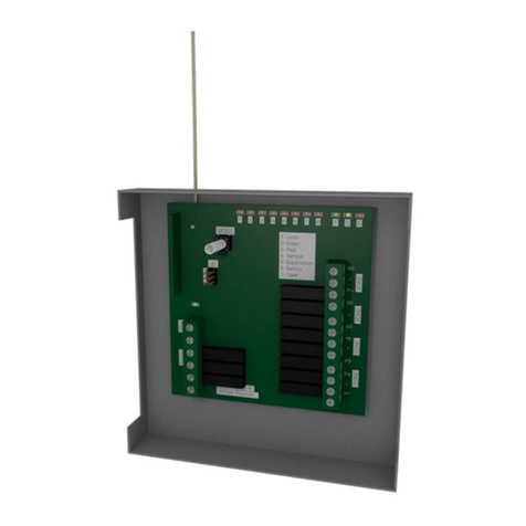
The IDS Digital Remote Receiver MK II is a 433.92 MHz RF receiver that is designed to connect to an
IDS816/EX or IDS1632 Alarm Panel. The receiver connects to the keypad bus (via D+ and D- terminals),
permitting the Alarm Panel to be armed and disarmed from remote transmitters. When remotes are
learned, they are assigned to USER CODES stored in the IDS Alarm Panel. This means that the Alarm
Panel is able to log ARM/DISARM events per user.
Functionality of the receiver is extended with two fully programmable relay outputs, which also makes this
receiver useful for stand-alone applications (without Alarm Panels).
1.2 Wiring and Configuration
1.3 Features
Up to 200 users in stand-alone mode.
In panel mode the number of users is panel dependant.
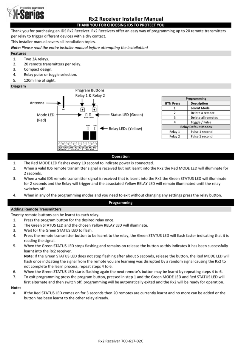
Three LEDs for communication.
Support for bus-wired and stand-alone operation.
Communicates with the Alarm Panel via a RS485 keypad bus.
Programmable via an 8-way DIP switch.
Onboard tamper switch.

IDS Digital Remote Receiver MKII 700-373-02CIssued April 2010
5
1.4 Electrical Specifications
Supply Voltage: 10 to 15 VDC
Current Consumption: 30mA
Relay Rating Contacts: 1 A @ 30 VDC
Minimum Receiver Sensitivity: ≤ -100 dBm
Receiver Frequency: 433.92 MHz
1.5 DIP Switches
There are no jumpers on this receiver, as the 6-pin dual in-line connector is used for version updates.
All of the programming is performed via DIP switches (1 - 8). These are used for programming the
functionality of the receiver, to learn remote buttons, change operating parameters, and to set the mode
of operation. These instructions use the terms “SET” and “CLEAR” to refer to the position of the relevant
DIP switches.
(Set = On, Clear = Off.)
During normal operation (STANDBY MODE) all switches are cleared, except the two that are used to
select STANDBY MODE options - see page 16 “Selecting Standby Mode” for more details on these
options.
DIP switches
Standby Mode
1
2
3
4
5
6
7
Default Settings
Panic Disable
0
0
0
0
0
0
1
Panic active when switch is OFF
Arm Protect
0
1
0
0
0
0
0
Prevents arm & stay arm signal re-
triggering for 20 second period
Standby Mode
0
0
0
0
0
0
0
1.6 LED Indication
There are three LEDs on the receiver PCB. A red, a green and an amber LED.
The amber LED is on when there is a satisfactory bus connection between the receiver and the Alarm
Panel.
The red and green LEDs can display a multitude of different signals to indicate receiver status. A full table
of red and green LED indications is included on page 13.

IDS Digital Remote Receiver MKII 700-373-02CIssued April 2010
6
2. Defaulting Procedure
2.1 Clearing and Defaulting the Receiver
There are three “reset” functions. These enable you to delete all remote users, or restore the factory
default settings for the relay parameters - or perform a complete clear and reset. This only needs to be
done if there are users/remotes that you want to delete. The three options work as follows:
2.2 Delete All Users/All Remote Transmitters
(All remotes are deleted - Parameter settings are not changed)
Set DIP switches 2, 5, 6, 7, and (lastly) 8.
Clear DIP switch 8 to delete all the remotes.
Clear all remaining switches to return to standby mode.
The ARMED LED stays on.
2.3 Parameter Reset
(Defaults all the parameters - remote buttons are NOT erased)
Set DIP switches 1, 5, 6, 7, and (lastly) 8.
Clear 8 to affect the reset.
Clear all remaining switches to return to standby mode.
The ARMED LED stays on.
2.4 Erase Remotes and Restore Factory Default
This will restore the receiver to its “as-new” factory default condition, ALL buttons are erased.
Set DIP switch 1, 2, 5, 6, 7, and (lastly) 8.
Clear 8 to restore the factory defaults and erase all remotes.
Clear all remaining switches to return to standby mode.
The ARMED LED stays on.
NOTE:
The above clears the remote receiver’s ID that has been assigned to the Alarm Panel. Use the installer
program location 0 to “remove missing devices”:
LOCATION 0 Defaulting of the panel or master user code
[#] [INSTALLER CODE] [*] [0] [*] [4] [*] and [#] to exit
NOTE:
When erasing remotes or defaulting them, please make sure that the receiver is not connected to the
Alarm Panel at that time. Once you have completed this function, then you may reconnect the receiver to
the panel.

IDS Digital Remote Receiver MKII 700-373-02CIssued April 2010
7
3. Panel Mode (Alarm Panel Functions)
These settings only apply to receivers being used with IDS Alarm Panels. All remotes follow these
settings, they cannot be different from one remote to the next.
3.1 Button Assignment (Alarm Panel Functions)
3.2 Add Remote to Panel
Use the following steps to add remote transmitters to the remote receiver connected to an IDS Alarm
Panel via the keypad bus.
1. Defaulting of the Remote Receiver is only for new installations of the Remote Receiver.
2. On the Alarm Panel, ADD the user codes that will be assigned to the remote receivers (one for
each). Do this only if the codes have not already been entered before.
NOTE:
If you are using a partitioned system, please note the following;
A: The user code must be allocated to the partition first.
[*] [Master Code] [*] [5] [*] [User Code] [*] [Partition Number] [*]
B: When learning the remote the client must use a keypad in the same partition as the user code.
3. On the remote receiver set DIP switch 3 (ON).
NOTE:
When connected to an Alarm Panel this switch may be left ON as the learn mode is only possible when
Option 8 is active, see below.
4. Enter the Alarm Panel user program mode:
Hold [*] till the beep (3-4 seconds), enter: [MASTER CODE] and press [*]
5. Select option 8, adding user remote, by entering:

IDS Digital Remote Receiver MKII 700-373-02CIssued April 2010
8
[8] [*]
The READY and ARMED LEDs will flash simultaneously on the keypad.
6. Enter the user code to be assigned to the remote transmitter:
[USER CODE] [*]
7. On the remote to be assigned to the user code above. Press:
(Any button)
This will assign the remote to the user code entered in step 6.
8. To add additional remotes press [*] on the keypad and repeat steps 6 and 7 for each remote
transmitter to be assigned or press [#] key to exit user program mode.
9. Clear DIP switch 3 if accessible.
Consult the Alarm Panel installer manual for instructions on how to delete USER CODES from the Alarm
Panel’s memory. Only delete USER CODES if so required, existing USER CODES can still be used.
3.3 Assigning Alarm Panel Functions to Remote Buttons
Remote Assignment
Function
Dipswitch
Learn remote
3
3 Sec panic disable
7
Arm protect
2
Panic remote only
6
To re-assign the button functions, follow the instructions below –remembering that these assignments
are globally applied to all remotes.
3.4 Assign Relay to Button
Changing the button that will be the relay button will not affect all learned remotes.
Set DIP switch 5, then 8.
The READY LED is on and the ARMED LED is flashing.
Set DIP switch 1 for relay 1 or 2 for relay 2.
Press the button to be the relay button (on a learned remote).
Clear 8 to save this setting.
The ARMED and READY LED’s will flash.
Clear other switches to return to standby mode.
The ARMED LED is on.

IDS Digital Remote Receiver MKII 700-373-02CIssued April 2010
9
3.5 Assign Panic Button
Changing the button that will be the panic button will affect all learned remotes.
Set DIP switch 4, then 8.
The READY LED will flash.
Press the button to be the panic button (on a learned remote).
Clear 8 to save settings.
The ARMED and READY LED’s will flash.
Clear other switches to return to standby mode.
The ARMED LED is on.
3.6 Assign Arm/Disarm Button
Changing the button that will arm the panel will affect all learned remotes.
Set DIP switch 3, then 8.
The READY LED will flash.
Press the button to be the arm button (on a learned remote).
Clear 8 to save this setting.
The ARMED and READY LED’s will flash.
Clear other switches to return to standby mode.
The ARMED LED is on.
NOTE:
When assigning buttons, make sure that the relay assignment is the way you require it (as per “6.4
Assign Relay Button”).
The new ARM/DISARM button will not trigger relay1. (If you change the default setting, the relay will not
follow suit.
3.7 Assign Stay Arm Button
Changing the button that will stay arm the panel will affect all learned remotes.
Set DIP switch 2, then 8.
The READY LED will flash.
Press the button to be the stay arm button (on a learned remote).
Clear 8 to save this setting.
The ARMED and READY LED’s will flash.
Clear other switches to return to standby mode.
The ARMED LED is on.
4. Selecting Standby Mode
On power up (with all the DIP switches cleared), the receiver enters standby mode, with the red LED on
and the green LED off. Two standby options can be selected via the DIP switches:
Panic disable
By default, this receiver will register a panic condition if ANY button on ANY learned IDS remote is held
down for three seconds. Setting DIP switch 7 (permanently) will DISABLE this feature.

IDS Digital Remote Receiver MKII 700-373-02CIssued April 2010
10
“Hold ANY button for three seconds” panic facility. Clearing this switch will permit a 3-second panic
press on any button of any learned remote to trigger the panic relay and cause a panic signal to be sent
to the Alarm Panel, triggering a panic event –which would also be recorded in the Alarm Panel’s event
log.
Arm protect
Setting DIP switch 2 (permanently) will prevent ARM and STAY ARM signals from being received any
more than once every 20 seconds.
Clear other switches to return to standby mode.
5. Stand-alone Mode
The stand-alone function does not need an Alarm Panel to work.
This is accomplished by setting the desired state on DIP switches 1 to 7 then switching DIP switch 8 on
then off.
5.1 Adding Remotes
Set DIP switch 3.
Press any button on any IDS remote to add that remote.
When all the required remotes have been added clear DIP switch 3.
These remotes will now operate as per the default settings –if these were not altered.
6. Operational Mode (PANEL AND STAND-ALONE)
6.1 Relay Retrigger Protection
Default is off for both relays. This prevents a relay from being triggered more than once for each button
press. With this option selected, the relevant relay will ignore any input for twenty seconds after the last
trigger.
Set DIP switches 5 and 7, then 8.
The ARMED LED will flash, whilst the READY LED stays on.
Set DIP switch 1 and/or 2 to select the relays for which this feature is to be enabled.
Clear DIP switch 8 to save settings.
The ARMED and READY LED’s will flash.
Clear other switches to return to standby.
The ARMED LED is on.
6.2 Relay Pulse/Toggle
Default –both relays are set to pulse. The relays can be set to either pulse, default, for the programmed
time, or toggle when activated.
Set DIP switches 5, 6, and 7, then 8.
The ARMED and READY LED’s flash fast, now.

IDS Digital Remote Receiver MKII 700-373-02CIssued April 2010
11
Set DIP switches 1 and2 for the corresponding relays to pulse or clear switches 1 and 2 to toggle.
Clear 8 to save settings.
THE ARMED and READY LED’s flash.
Clear other switches to return to standby.
The ARMED LED is on.
6.3 Assign Panic Relay
A panic relay will be triggered by a panic remote - or by holding down any button on a learned remote for
3 seconds (if this feature is enabled).
Set DIP switches 6 then 7.
The ARMED LED is on, whilst the READY LED flashes.
Set DIP switch 1 OR 2 to select which relay to activate when a Panic Event occurs.
Clear DIP switch 8 to commit panic relay choice to memory.
The ARMED and READY LED’s will flash.
Clear other switches to return to standby mode.
The ARMED LED is on.
6.4 Assign Relay Button
Changing the button that triggers a relay will affect the remote used to change it as well as any
remotes that are subsequently learned. The remotes that have already been learned will keep their
previous button to relay settings. (When pressing a button to assign to a relay the keypad gives two
beeps to indicate the change).
Set DIP switch 5, then 8.
The READY LED is on, whilst the ARMED LED flashes.
Set either DIP switch 1 or 2 to select the desired relay.
Press the button on the remote that is required to activate the relay.
Any button (on that remote) that was previously programmed to activate that relay will no longer do so.
Repeat for the other relay if so required.
Clear 8 to save this setting.
The ARMED and READY LED’s will flash.
Clear other switches to return to standby mode.
The ARMED LED is on.
6.5 Relay Secure/Safe Mode (Default is Secure for both relays)
Secure Mode: Loss of supply power will not switch the state of the relay –(Normally relaxed).
Safe Mode: Loss of supply power will cause the relay to switch state –(Normally activated). When the
relays are set to Safe Mode, the relay terminal contact N/O and N/C will be switched around.
Set DIP switch 6, then 8.
The ARMED LED will flash, whilst the READY LED flashes fast.
Use DIP switches 1 and 2 to select which relays to set for safe mode.
Clear DIP switch 8.
Clear DIP switch 6.
The ARMED and READY LED’s will flash.

IDS Digital Remote Receiver MKII 700-373-02CIssued April 2010
12
Clear other switches to return to standby mode.
The ARMED LED is on.
6.6 Relay Parameter Selection and Setting
Parameter Reset (Defaults all the parameters - remote buttons are NOT erased)
Set DIP switch 1, 5, 6, and 7.
Set DIP switch 8.
Clear DIP switch 8, the receiver returns to standby mode.
6.7 Relay Pulse Period
Default 3 seconds for both relays.
Set DIP switch 7, then 8
The ARMED LED flashes very fast.
Select DIP switch 1 (for relay 1) or 2 (for relay 2) or both 1 and 2 for relays 1 and 2.
Wait for the time you would like the relay to pulse
Clear DIP switch 8 to commit timed period to memory
The ARMED and READY LED’s will flash.
Clear other switches to return to standby mode.
7. Fault Finding
7.1 Amber LED Indicator
The sole function of this LED is to indicate when there is a valid bus connection between the receiver and
an IDS Alarm Panel.
7.2 Red and Green LED Indicators
LED behaviour in STANDBY MODE
When the receiver decodes a valid (but unlearned IDS remote), the red LED will temporarily turn off. If it
decodes a learned remote, the green LED will turn on for the period that the receiver signal is present.
Upon decoding the learned remote, the respective relay is triggered and an appropriate message is sent
to the Alarm Panel.
LED behaviour in PROGRAMMING MODE
During the programming process, the green and red LEDs indicate the current programming function
with combinations of FOUR different indications:
Status
Action
OFF
the LED is OFF
ON
the LED is shining continuously
Slow
the LED is blinking slowly (one pulse per second)
Fast
the LED is blinking fast (five pulses per second)

IDS Digital Remote Receiver MKII 700-373-02CIssued April 2010
13
Setting DIP switch 8 causes the receiver
to read the DIP switch settings
Clearing DIP switch 8 commits the selection
and returns the receiver to STANDBY MODE.
7.3 Programming Quick Reference Table
NOTE:
Familiarise yourself fully with the relevant sections before programming the receiver. (This table is for
quick reference purposes only, and does not show the full details.)
IMPORTANT
Before beginning any programming:
Clear all DIP switches to ensure that they are set and reset in the
correct logical sequence.
The following table shows the LED indication for each programming function selected:
FUNCTION
DIP SWITCH SETTING
LED STATUS
1
2
3
4
5
6
7
8
RED
GRN
Learn Relay Pulse Period
0
0
0
0
0
0
1
0
Fast
OFF
Relay Normal or Fail Safe
0
0
0
0
0
1
0
0
Slow
Fast
Assign Panic Relay
0
0
0
0
0
1
1
0
Slow
OFF
Enable Relay Retrigger Protection
0
0
0
0
1
0
1
0
Fast
ON
Relay Pulse/Toggle
0
0
0
0
1
1
1
0
Fast
Fast
Assign Button to Relay
0
0
0
0
1
0
0
0
Slow
ON
Assign Panic Button
0
0
0
1
0
0
0
0
OFF
Fast
Assign Arm/Disarm Button
0
0
1
0
0
0
0
0
OFF
Fast
Assign Stay Arm Button
0
1
0
0
0
0
0
0
OFF
Fast
Factory Default
1
0
0
0
1
1
1
0
Fast
Fast
Delete All Users
0
1
0
0
1
1
1
0
Slow
Slow
Factory Defaults
Both relays set to pulse for 3 seconds.
No retrigger protection.
No panic button enabled.
Relay 1 for button 1.
Relay 2 for button 3.
Button 1 for –ARM / DISARM.
Button 3 for Stay ARM.
Relay 2 for Panic when enabled.

IDS Digital Remote Receiver MKII 700-373-02CIssued April 2010
14

IDS Digital Remote Receiver MKII 700-373-02CIssued April 2010
15

IDS Digital Remote Receiver MKII 700-373-02CIssued April 2010
16
Table of contents
Other IDS Receiver manuals

