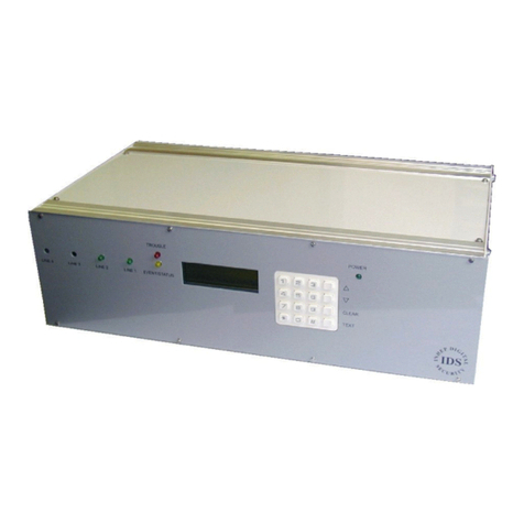
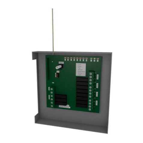
IDS 860-06-0003 User manual

ID
S
Digita
l
Wireles
s
Remot
e
Receive
r
ID
S
Digita
l
Wireles
s
Remot
e
Receive
r
ID
S
Digita
l
Wireles
s
Remot
e
Receiver
IDS
Wireless
Remote
Receiver
(Digital)
P/N
860-06-0003
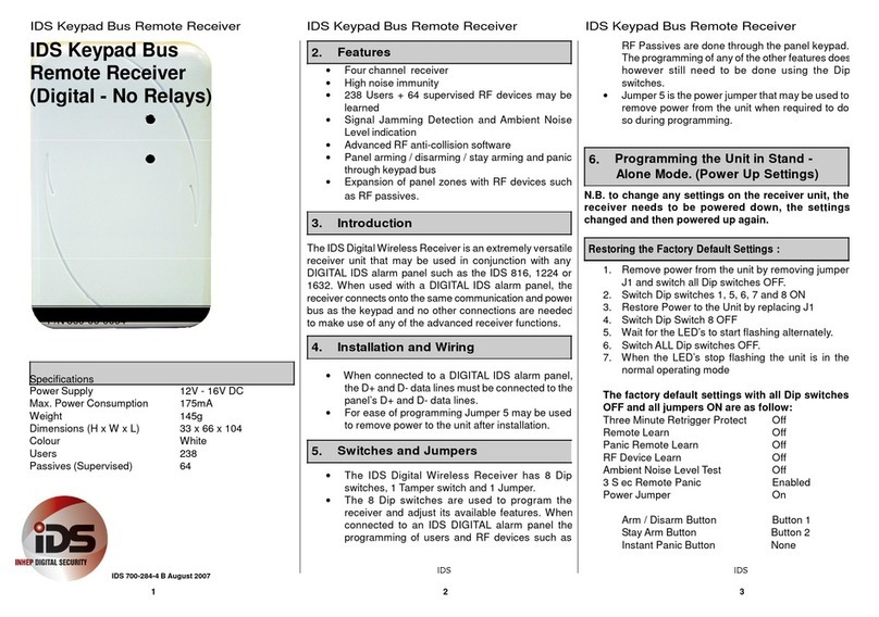
Specifications
Power
Supply
12V
-
16V
DC
Max.
Power
Consumption
175mA
Weight
145g
Dimensions
(H
x
W
x
L)
33
x
66
x
104
Colour
White
Channels
4
Users
238
Passives
(Supervised)
64
2
.
Features
•
Four
channel
receiver
•
High
noise
immunity
•
238
Users
+
64
supervised
RF
devices
may
be
learned
•
Signal
Jamming
Detection
and
Ambient
Noise
Level
indication
•
Advanced
RF
anti-collision
software
•
Individual
relay
pulse
periods
selectable
up
to
10
minutes
•
Dedicated
panic
remotes
may
be
learned
•
Selectable
retrigger
protection
on
any
relay
•
Panel
arming
/
disarming
/
stay
arming
and
panic
through
keypad
bus
•
Expansion
of
panel
zones
with
RF
devices
such
as
RF
passives.
3. Introduction
The
IDS
Digital
Wireless
Receiver
is
an
extremely
versatile
receiver
unit
that
may
be
used
either
as
a
standalone
product
or
in
conjunction
with
any
DIGITAL
IDS
alarm
panel
such
as
the
IDS
816,
1224
or
1632.
When
used
with
a
DIGITAL
IDS
alarm
panel,
the
receiver
connects
onto
the
same
communication
and
power
bus
as
the
keypad
and
no
other
connections
are
needed
to
make
use
of
any
of
the
advanced
receiver
functions.
4. Installation and Wiring
•
The
IDS
Digital
Wireless
receiver
may
be
used
in
either
a
standalone
mode
or
connected
to
an
IDS
DIGITAL
alarm
panel.
•
When
used
in
standalone
mode,
the
receiver
needs
a
supply
of
between
12V
and
16V
DC.
The
Data
lines
D+
and
D-
do
not
need
to
be
connected.
•
When
connected
to
a
DIGITAL
IDS
alarm
panel,
the
D+
and
D-
data
lines
must
be
connected
to
the
panel’s
D+
and
D-
data
lines.
(Connection
of
relays
to
arm
and
disarm
the
panel
via
zones
is
NOT
needed.
Arming
and
disarming
of
the
panel
is
done
through
the
data
bus.)
•
Th
e
Normall
y
Ope
n
(NO)
,
Normall
y
Close
d
(NC)
and
Common
(COM)
outputs
of
all
four
relays
are
available
to
be
connected
to
external
devices
such
as
gate
operators
or
other
alarm
panels.
•
Relay
4’s
NO
contact
is
only
available
with
jumper
6
in
position
2.
When
Jumper
6
is
in
position
1
Relay
4’s
NO
contact
is
connected
to
ground
via
the
tamper
switch
on
the
receiver.
•
For
ease
of
programming
Jumper
5
may
be
used
to
remove
power
to
the
unit
after
installation.
5. Switches, Jumpers, and Relays
•
The
IDS
Digital
Wireless
Receiver
has
8
Dip
switches,
1
Tamper
switch
and
2
Jumpers
•
The
8
Dip
switches
are
used
to
program
the
receiver
and
adjust
its
available
features.
When
connected
to
an
IDS
DIGITAL
alarm
panel
the
programming
of
users
and
RF
devices
such
as
RF
Passives
are
done
through
the
panel
keypad.
The
programming
of
any
of
the
other
features
does
however
still
need
to
be
done
using
the
Dip
switches.
•
Jumper
5
is
the
power
jumper
that
may
be
used
to
remove
power
from
the
unit
when
required
to
do
so
during
programming.
•
Jumper
6
selects
between
Relay
4’s
NO
contact
or
the
Tamper
Switch
Contact.
The
tamper
switch
is
internally
connected
to
ground.
•
Any
of
the
relay
outputs
may
be
used
to
switch
a
maximum
of
3A
at
a
maximum
of
24V
DC.
The
relays
are
not
intended
for
switching
high
voltage
signals
directly
such
as
lights
or
motors.
ID
S
700
-
284
-
3
JUL
Y
200
5
RE
V
B
VER
1.04
1
2
3

ID
S
Digita
l
Wireles
s
Remot
e
Receive
r
ID
S
Digita
l
Wireles
s
Remot
e
Receive
r
ID
S
Digita
l
Wireles
s
Remot
e
Receiver
6
.
Programmin
g
th
e
Uni
t
i
n
Stand
-
Alone
Mode. (Power Up Settings)
N.B.
to
change
any
settings
on
the
receiver
unit,
the
receiver
needs
to
be
powered
down,
the
settings
changed
and
then
powered
up
again.
Restoring
the
Factory
Default
Settings:
1.
Remove
power
from
the
unit
by
removing
jumper
J5
and
switch
all
Dip
switches
OFF.
2.
Switch
Dip
switches
1,
5,
6,
7
and
8
ON
3.
Restore
Power
to
the
Unit
by
replacing
J5
4.
Switch
Dip
Switch
8
OFF
5.
Wait
for
the
LED’s
to
start
flashing
alternately.
6.
Switch
ALL
Dip
switches
OFF.
7.
When
the
LED’s
stop
flashing
the
unit
is
in
the
normal
operating
mode
The
factory
default
settings
with
all
Dip
switches
OFF
and
all
jumpers
ON
are
as
follow:
Three
Minute
Retrigger
Protect
Off
Remote
Learn
Off
Panic
Remote
Learn
Off
RF
Device
Learn
Off
Ambient
Noise
Level
Test
Off
Device
Failure
Relay
Disabled
Panic
Relay
Enabled
3
Sec
Remote
Panic
Enabled
Relays
Pulse
Relay
4
Output
Selected
Power
Jumper
On
Relay
Pulse
Period
3
Sec
Relays
Safe
/
Secure
Secure
Panic
Relay
Relay
4
Device
Failure
Relay
Relay
3
RF
Device
Output
Relay
None
Remote
Button
Outputs
Button
1
Relay
1
Button
2
Relay
2
Button
3
Relay
3
Butto
n
4
Rela
y
4
Ar
m
/
Disar
m
Butto
n
Butto
n
1
Stay
Arm
Button
Button
2
Instant
Panic
Button
None
3
Sec
Hold
for
Panic
Button
All
Relay
3
Min
Retrigger
Protect
None
Signal
Jamming
Detect
Period
30s
Device
Not
Reporting
1hr
max
Deleting
ALL
the
User
Remotes:
1.
Remove
power
from
the
unit
by
removing
jumper
J5
and
switch
all
Dip
switches
OFF.
2.
Switch
Dip
switches
2,
5,
6,
7
and
8
ON
3.
Restore
Power
to
the
Unit
by
replacing
J5
4.
Switch
Dip
Switch
8
OFF
5.
Wait
for
the
LED’s
to
start
alternating
6.
Switch
ALL
Dip
switches
OFF.
7.
When
the
LED’s
stop
flashing
the
unit
is
in
the
normal
operating
mode
Deleting
ALL
Supervised
RF
Devices
(e.g.
RF
Passive
IR’s):
1.
Remove
power
from
the
unit
by
removing
jumper
J5
and
switch
all
Dip
switches
OFF.
2.
Switch
Dip
switches
3,
5,
6,
7
and
8
ON
3.
Restore
Power
to
the
Unit
by
replacing
J5
4.
Switch
Dip
Switch
8
OFF
5.
Wait
for
the
LED’s
to
start
flashing
alternately.
6.
Switch
ALL
Dip
switches
OFF.
7.
When
the
LED’s
stop
flashing
the
unit
is
in
the
normal
operating
mode
Adjusting
the
Relay
Pulse
Periods:
1.
Remove
power
from
the
unit
by
removing
jumper
J5
and
switch
all
Dip
switches
OFF.
2.
Switch
Dip
switches
7
and
8
ON
3.
Restore
Power
to
the
Unit
by
replacing
J5
4.
To
adjust
relay
1’s
pulse
period,
switch
Dip
switch
1
ON.*
5.
Wait
for
as
long
as
the
pulse
needs
to
be.
(Up
to
1
0
minutes)
6
.
Switc
h
Di
p
switc
h
1
OFF
.
(Fo
r
rela
y
1’
s
pulse
period)
7.
Switch
Dip
switch
8
OFF.
8.
Wait
for
the
LED’s
to
start
flashing
alternately.
9.
Switch
ALL
Dip
switches
OFF.
10.
When
the
LED’s
stop
flashing
the
unit
is
in
the
normal
operating
mode
Changing
Between
Relay
Safe
and
Secure
Modes:
1.
Remove
power
from
the
unit
by
removing
jumper
J5
and
switch
all
Dip
switches
OFF.
2.
Switch
Dip
switches
6
and
8
ON
3.
Restore
Power
to
the
Unit
by
replacing
J5
4.
To
make
Relay
2
and
4
Fail
Safe,
switch
Dip
switches
2
and
4
ON.*
(Any
relay
not
selected
will
be
Fail
Secure.)
5.
Switch
Dip
switch
8
OFF.
6.
Wait
for
the
LED’s
to
start
flashing
alternately.
7.
Switch
ALL
Dip
switches
OFF.
8.
When
the
LED’s
stop
flashing
the
unit
is
in
the
normal
operating
mode
Selecting
the
Panic
Relay
Output:
1.
Remove
power
from
the
unit
by
removing
jumper
J5
and
switch
all
Dip
switches
OFF.
2.
Switch
Dip
switches
6,
7
and
8
ON
3.
Restore
Power
to
the
Unit
by
replacing
J5
4.
Select
the
relay
to
be
the
Panic
Relay.*
(If
no
relay
is
selected,
the
panic
relay
will
be
disabled.)
5.
Switch
Dip
switch
8
OFF.
6.
Wait
for
the
LED’s
to
start
flashing
alternately.
7.
Switch
ALL
Dip
switches
OFF.
8.
When
the
LED’s
stop
flashing
the
unit
is
in
the
normal
operating
mode
*
Where
indicated
Dip
switch
1
represents
Relay
1,
Dip
switch
2
represents
Relay
2,
Dip
switch
3
represents
Relay
3
and
Dip
switch
4
represents
Relay
4.
ID
S
700
-
284
-
3
JUL
Y
200
5
RE
V
B
VE
R
1.40
4
5
6

ID
S
Digita
l
Wireles
s
Remot
e
Receive
r
ID
S
Digita
l
Wireles
s
Remot
e
Receiv
e
r
ID
S
Digita
l
Wireles
s
Remot
e
Receiver
Selectin
g
th
e
Rela
y
t
o
Activat
e
Whe
n
a
Remot
e
Button
is
Pressed:
1.
Remove
power
from
the
unit
by
removing
jumper
J5
and
switch
all
Dip
switches
OFF.
2.
Switch
Dip
switches
5
and
8
ON
3.
Restore
Power
to
the
Unit
by
replacing
J5
4.
Select
the
relay
to
be
the
new
Output
Relay.*
(If
no
relay
is
selected,
no
relay
will
be
activated
when
the
remote
button
is
pressed.)
5.
Press
the
button
on
a
learned
remote
that
must
activate
the
selected
relay
output.
6.
Switch
Dip
switch
8
OFF.
7.
Wait
for
the
LED’s
to
start
flashing
alternately.
8.
Switch
ALL
Dip
switches
OFF.
9.
When
the
LED’s
stop
flashing
the
unit
is
in
the
normal
operating
mode
Protecting
Relays
from
retriggering
within
3
minutes
after
a
previous
trigger:
1.
Remove
power
from
the
unit
by
removing
jumper
J5
and
switch
all
Dip
switches
OFF.
2.
Switch
Dip
switches
5,
7
and
8
ON
3.
Restore
Power
to
the
Unit
by
replacing
J5
4.
Select
the
relay(s)
to
be
retrigger
protected.*
5.
Switch
Dip
switch
8
OFF.
6.
Wait
for
the
LED’s
to
start
flashing
alternately.
7.
Switch
ALL
Dip
switches
OFF.
8.
When
the
LED’s
stop
flashing
the
unit
is
in
the
normal
operating
mode
Assigning
a
Relay
to
be
Activated
when
a
RF
Device
is
Triggered:
1.
Remove
power
from
the
unit
by
removing
jumper
J5
and
switch
all
Dip
switches
OFF.
2.
Switch
Dip
switches
5,
6
and
8
ON
3.
Restore
Power
to
the
Unit
by
replacing
J5
4.
Select
the
relay
to
be
activated.*
(If
no
relay
is
selected,
no
relay
will
be
activated
when
the
remote
button
is
pressed.)
5.
Trigger
the
device
that
must
activate
the
selected
Rela
y
Output.
6
.
Switc
h
Di
p
switc
h
8
OFF.
7.
Wait
for
the
LED’s
to
start
flashing
alternately.
8.
Switch
ALL
Dip
switches
OFF.
9.
When
the
LED’s
stop
flashing
the
unit
is
in
the
normal
operating
mode
Assigning
a
Dedicated
Panic
Button
to
a
Remote:
N.B.
This
Function
will
affect
ALL
remotes.
1.
Remove
power
from
the
unit
by
removing
jumper
J5
and
switch
all
Dip
switches
OFF.
2.
Switch
Dip
switches
4
and
8
ON
3.
Restore
Power
to
the
Unit
by
replacing
J5
4.
Press
the
button
on
a
known
remote
that
will
become
an
instant
panic
button.
5.
Switch
Dip
switch
8
OFF.
6.
Wait
for
the
LED’s
to
start
flashing
alternately.
7.
Switch
ALL
Dip
switches
OFF.
8.
When
the
LED’s
stop
flashing
the
unit
is
in
the
normal
operating
mode
Assigning
an
Arm
/
Disarm
Button
on
a
Remote:
N.B.
This
Function
will
affect
ALL
remotes.
1.
Remove
power
from
the
unit
by
removing
jumper
J5
and
switch
all
Dip
switches
OFF.
2.
Switch
Dip
switches
3
and
8
ON
3.
Restore
Power
to
the
Unit
by
replacing
J5
4.
Press
the
button
on
a
known
remote
that
will
become
the
Arm
/
Disarm
button.
5.
Switch
Dip
switch
8
OFF.
6.
Wait
for
the
LED’s
to
start
flashing
alternately.
7.
Switch
ALL
Dip
switches
OFF.
8.
When
the
LED’s
stop
flashing
the
unit
is
in
the
normal
operating
mode
Assigning
a
Stay
Arm
Button
on
a
Remote:
N.B.
This
Function
will
affect
ALL
remotes.
1.
Remove
power
from
the
unit
by
removing
jumper
J5
and
switch
all
Dip
switches
OFF.
2.
Switch
Dip
switches
2
and
8
ON
3
.
Restore
Power
to
the
Unit
by
replacing
J5
4
.
Pres
s
th
e
butto
n
o
n
a
know
n
remot
e
tha
t
will
become
the
Stay
Arm
button.
5.
Switch
Dip
switch
8
OFF.
6.
Wait
for
the
LED’s
to
start
flashing
alternately.
7.
Switch
ALL
Dip
switches
OFF.
8.
When
the
LED’s
stop
flashing
the
unit
is
in
the
normal
operating
mode
Assigning
the
Device
Failure
Output
Relay:
1.
Remove
power
from
the
unit
by
removing
jumper
J5
and
switch
all
Dip
switches
OFF.
2.
Switch
Dip
switches
4,
7
and
8
ON
3.
Restore
Power
to
the
Unit
by
replacing
J5
4.
Switch
Dip
switch
4
OFF
5.
Select
the
relay
to
be
the
Device
Failure
Relay.*
(If
no
relay
is
selected,
the
device
failure
relay
will
be
disabled.)
6.
Switch
Dip
switch
8
OFF.
7.
Wait
for
the
LED’s
to
start
flashing
alternately.
8.
Switch
ALL
Dip
switches
OFF.
9.
When
the
LED’s
stop
flashing
the
unit
is
in
the
normal
operating
mode
Learning
a
New
RF
Device
such
as
a
RF
Passive
IR:
1.
Remove
power
from
the
unit
by
removing
jumper
J5
and
switch
all
Dip
switches
OFF.
2.
Switch
Dip
switches
3,
7
and
8
ON
3.
Restore
Power
to
the
Unit
by
replacing
J5
4.
Press
the
TAMPER
switch
on
the
Device
to
be
Learned
5.
Switch
Dip
switch
8
OFF.
6.
Remove
power
from
the
unit
and
adjust
Dip
switch
setting
as
needed.
7.
Restore
power
to
the
unit.
When
the
LED’s
stop
flashing
the
unit
will
be
in
normal
operating
mode.
*
Where
indicated
Dip
switch
1
represents
Relay
1,
Dip
switch
2
represents
Relay
2,
Dip
switch
3
represents
Relay
3
and
Dip
switch
4
represents
Relay
4.
ID
S
700
-
284
-
3
JUL
Y
200
5
RE
V
B
VER
1.04
7
8
9

ID
S
Digita
l
Wireles
s
Remot
e
Receive
r
ID
S
Digita
l
Wireles
s
Remot
e
Receive
r
ID
S
Digita
l
Wireles
s
Remot
e
Receiver
7
.
Programmin
g
th
e
Uni
t
i
n
Stand
-
Alone
Mode. (Normal Settings)
These
settings
may
be
adjusted
during
normal
operation
and
it
is
not
necessary
to
power
the
unit
down
for
the
settings
to
take
effect.
Remote
Arm
or
Disarm
3
Minute
Retrigger
Protecting:
1.
Switch
Dip
switch
2
ON
to
enable
retrigger
protecting
Learning
New
Remotes:
1.
Switch
Dip
switch
3
ON
to
enable
learning
of
new
remotes
2.
Press
any
button
on
the
remotes
to
be
learned.
3.
Switch
Dip
switch
3
OFF
to
exit
the
learn
mode.
To
indicate
the
Ambient
Noise
Level:
N.B.
This
function
must
be
disabled
during
normal
operation
This
function
allows
the
testing
of
ambient
noise
in
the
environment
surrounding
the
receiver
during
installation.
1.
Switch
Dip
switch
4
ON
to
enable
noise
level
testing.
2.
ONLY
install
the
receiver
in
an
environment
with
Normal
or
Better
Noise
Levels.
During
Noise
Testing
the
LED’s
indicate
the
following:
2
.
Press
any
button
on
the
remotes
to
be
learned.
3.
Switch
Dip
switch
6
OFF
to
exit
the
learn
mode.
Disable
the
3
second
Hold
for
Panic
Feature:
1.
To
disable
the
3
second
hold
for
panic
feature
on
ALL
remotes
switch
Dip
switch
7
ON.
Changing
the
Relays
from
Pulsing
to
Toggling:
1.
Remove
power
from
the
unit
by
removing
jumper
J5
and
switch
all
Dip
switches
OFF.
2.
Switch
Dip
switches
5,
6,
7
&
8
on.
3.
Restore
the
power
to
the
Unit
by
replacing
J5.
4.
To
select
toggling
relays,
use
Dip
switches
1,
2,
3
&
4
for
Relays
1,
2,
3
&
4.
5.
Switch
Dip
switch
8
off.
6.
Wait
for
the
LED’s
to
start
alternating.
7.
Switch
all
Dip
switches
off
and
set
Dip
switches
to
the
desired
setting.
8. Programming a Unit Connected to a
DIGITAL IDS alarm panel.
When
connected
to
a
DIGITAL
IDS
alarm
panel,
programming
of
the
unit
is
as
for
the
Stand-
Alone
mod
e
wit
h
th
e
followin
g
exceptions.
9
.
Connector
,
Switc
h
an
d
Jumpe
r
Positions
10.Program Summary and LED Indications:
S w i t c h
S e t t i n g s
R
G
F u n c t i o n
1
2
3
4
5
6
7
8
~
~
~
~
~
~
1
0
1
0
P A N I C
D I S A B L E
~
~
~
~
~
1
~
0
1
2
L E A R N
P A N I C
~
~
~
~
1
~
~
0
2
0
E R R O R
R E L A Y
~
~
~
1
~
~
~
0
1
0
T E S T
N O I S E
~
~
1
~
~
~
~
0
1
4
L E A R N
~
1
~
~
~
~
~
0
1
0
R E T R I G
P R O T E C T
1
~
~
~
~
~
~
0
1
0
0
0
0
0
0
0
1
1
3
0
P U L S E
P E R I O D
RED
LED
GREEN
LED
NOISE
LEVEL
Learnin
g
an
d
Deletin
g
Individua
l
Use
r
Remotes:
1.
To
learn
a
new
user
remote,
leave
Dip
switch
3
0
0
0
0
0
1
0
1
4
3
S A F E / S E C U R
E
0
0
0
0
0
1
1
1
4
0
P A N I C
R E L A Y
0
0
0
0
1
0
0
1
4
1
R E L A Y
F O R
OF
F
OF
F
VER
Y
LOW
OFF SLOW LOW
OFF FAST NORMAL
SLOW ON HIGH
FAST ON VERY HIGH
ON ON POSSIBLE JAMMING
Enabling
the
Device
Failure
Relay
Output:
1
.
Switch
Dip
switch
5
ON
ON
.
(i
t
nee
d
no
t
b
e
switche
d
OF
F
fo
r
normal
operation
when
connected
to
an
IDS
DIGITAL
alarm
panel)
2.
Follow
the
user
manual
of
the
DIGITAL
IDS
alarm
panel
for
learning
new
users.
Learning
New
Supervised
RF
Devices
and
deleting
Devices
by
Zone
allocation:
1.
Follow
the
user
manual
of
the
DIGITAL
IDS
alarm
panel
for
learning
new
RF
devices
and
deleting
RF
devices
by
zone.
0
0
0
0
1
0
1
1
3
1
R E L A
Y
R E T R I G G E
R
0
0
0
0
1
1
0
1
0
4
R E L A Y
F O R
D E V I C E
0
0
0
1
0
0
0
1
0
3
P A N I C
B U T T O N
0
0
1
0
0
0
0
1
0
3
A R M
B U T T O N
0
1
0
0
0
0
0
1
0
3
S T A Y
B U T T O N
0
0
0
1
0
0
1
1
2
1
E R R O R
R E L A Y
0
0
1
0
0
0
1
1
1
3
L E A R N
D E V I C E
0
1
0
0
0
0
1
1
3
2
R E C E IV E R
ID
0
0
0
0
1
1
1
1
1
2
R E L A Y
P U L S E
/
T O G G L E
0
0
1
0
1
1
1
1
4
4
D E L E T E
D E V I C E S
0
1
0
0
1
1
1
1
4
4
D E L E T E
R E M O T E S
1
0
0
0
1
1
1
1
3
3
F A C T O R
Y
R E S E T
S
Lear
n
Ne
w
Pani
c
Remotes:
1.
Switch
Dip
Switch
6
ON
0
=
O F
F
R
=
R E
D
L E
D
1
=
O N
G
=
G R E E N
L E D
2
=
B L I N K
3
=
F A S T
4
=
S L O W
5
=
ALT
3
4
M E M O R
Y
F U L
L
1
1
B U S Y
S I G N A L
0
0
I N V A L I D
S I G N A L
5
5
L O W
B A T T
ID
S
700
-
284
-
3
JUL
Y
200
5
RE
V
B
VE
R
1.40
10
11
12
Other IDS Receiver manuals

