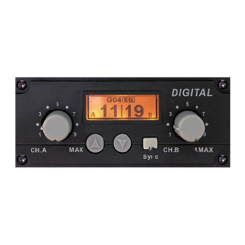
IDS 400 User manual


IDS Base Station Receiver 400 700-179-02B Issued January 2009 2
Contents
ContentsContents
Contents
1.
1.1.
1. IDS BASE STATION REC
IDS BASE STATION RECIDS BASE STATION REC
IDS BASE STATION RECEIVER
EIVEREIVER
EIVER................................
................................................................
................................................................
................................................................
................................................................
................................................................
................................ 6
66
6
1.1 SPECIFICATIONS .......................................................................................................................... 7
2.
2.2.
2. INSTALLATION
INSTALLATIONINSTALLATION
INSTALLATION................................
................................................................
................................................................
................................................................
................................................................
................................................................
........................................................
................................................
........................ 9
99
9
2.1 FULL INSTALLATION REQUIREMENTS .............................................................................................. 9
2.2 CONNECTING UP FULL INSTALLATION........................................................................................... 10
2.2.1 IDS BSR400 Installation.................................................................................................. 10
2.2.2 IDS BSR Installation........................................................................................................ 11
2.2.3 Installing the Battery....................................................................................................... 11
2.2.4 Ground Connection ....................................................................................................... 13
2.2.5 Connecting U ............................................................................................................... 13
3.
3.3.
3. OPERATION
OPERATIONOPERATION
OPERATION................................
................................................................
................................................................
................................................................
................................................................
................................................................
..........................................................
....................................................
.......................... 14
1414
14
3.1 FRONT PANEL LED.................................................................................................................... 15
3.1.1 AC Su ly LED............................................................................................................... 15
3.1.2 Trouble LED ................................................................................................................... 15
3.1.3 Event LED....................................................................................................................... 15
3.1.4 Line Card LED................................................................................................................ 15
3.2 KE PAD .................................................................................................................................... 15
3.2.1 Navigating and Editing ................................................................................................... 16
3.2.2 Viewing Events in the Log............................................................................................... 17
3.2.3 Version Dis lay, Print and Serial Out ut Facility.............................................................. 18
3.3 IDS BSR400 SETUP .................................................................................................................. 21
3.3.1 Date and Time ............................................................................................................... 21
3.3.2 Printer............................................................................................................................. 21
3.3.3 Monitoring Program Setu ............................................................................................. 21
3.3.4 Sescoa Su erfast........................................................................................................... 21
3.3.5 Format O tion Selection ................................................................................................ 22
3.3.6 SIA Handshake Enabled ................................................................................................ 22
3.3.7 Plain Library.................................................................................................................... 22
3.3.8 General Installations Management................................................................................. 22
3.4 TESTING.................................................................................................................................... 22
3.5 ALARM AND SSTEM EVENTS ...................................................................................................... 23
3.6 THE EVENT LOG ........................................................................................................................ 23
3.6.1 Viewing the Event Log.................................................................................................... 23
3.6.2 Event and Error Formats................................................................................................. 23
3.6.3 Viewing the TROUBLE Log............................................................................................. 26
3.7 CORRECTING TROUBLE CONDITIONS ........................................................................................ 27
3.7.1 Line Trouble ................................................................................................................... 27
3.7.2 AC Loss ......................................................................................................................... 27
3.7.3 Low System Battery........................................................................................................ 27
3.7.4 Comms Absent .............................................................................................................. 27
3.7.5 Printer Error .................................................................................................................... 28
3.7.6 Line Card Absent ........................................................................................................... 28
4.
4.4.
4. PROGRAM MODE
PROGRAM MODEPROGRAM MODE
PROGRAM MODE................................
................................................................
................................................................
................................................................
................................................................
................................................................
.................................................
..................................
................. 29
2929
29
4.1 ENTERING AND NAVIGATING PROGRAM MODE .............................................................................. 30
4.1.1 Direct Location of Program Mode Setting ...................................................................... 30
4.1.2 Program Mode Menu Ma ............................................................................................. 31
4.2 FIRMWARE VERSION M000........................................................................................................ 33

IDS Base Station Receiver 400 700-179-02B Issued January 20093
4.3 STATION SETUP M100.............................................................................................................. 33
4.3.1 Base Station ID M101................................................................................................... 33
4.3.2 Master ID M102............................................................................................................ 33
4.3.3 Date M103 ................................................................................................................... 33
4.3.4 Time M104................................................................................................................... 33
4.3.5 Load Defaults M105..................................................................................................... 33
4.3.6 Clear Un-viewed Count M106 ...................................................................................... 34
4.3.7 Format O tions M107 .................................................................................................. 34
4.4 PRINTER SETUP M200.............................................................................................................. 37
4.4.1 Enable Printer M201 ..................................................................................................... 37
4.4.2 Plain Library M202........................................................................................................ 39
4.4.3 Plain Library Overview .................................................................................................... 39
4.4.4 Plain Library Setu M203.............................................................................................. 39
4.5 EVENT ALARM SETUP M300...................................................................................................... 40
4.5.1 Event Buzzer M301....................................................................................................... 40
4.5.2 Event Relay M302......................................................................................................... 41
4.5.3 Tagged Buzzer Events M303........................................................................................ 41
4.5.4 Contact ID Tagged Buzzer Events M304 M305.......................................................... 41
4.5.5 SIA Tagged Buzzer Events M306 M307...................................................................... 43
4.5.6 Wake-u Alarm M308................................................................................................... 44
4.6 SERIAL OUTPUT SETUP M400 ................................................................................................... 44
4.6.1 Format M41x ................................................................................................................ 45
4.6.2 Enable Serial M411 ...................................................................................................... 45
4.6.3 Event Date/Pre/Post M412 ........................................................................................... 45
4.6.4 Heart Beat (Poll) Date/Pre/Post M413 .......................................................................... 45
4.6.5 Enable Year Out ut M414 ............................................................................................ 46
4.6.6 Enable CALL ID M415 .................................................................................................. 46
4.6.7 Format Event Code M416 M417 M418..................................................................... 46
4.6.8 Sout O tion M419........................................................................................................ 49
4.6.9 Delay between Sout M421 ........................................................................................... 49
4.6.10 Heart Beat Period M422............................................................................................... 50
4.6.11 Ack Wait Period M423 .................................................................................................. 50
4.6.12 Event/Ack Re eats M424 ............................................................................................. 50
4.6.13 Basic Signal Protocol [1]................................................................................................ 50
4.6.14 Su ervisory Poll (Heart Beat) Signal Protocol [1]............................................................ 51
4.6.15 Status Re ort Messages [1]........................................................................................... 51
4.6.16 SIA-ID Protocol 1 [3] ...................................................................................................... 52
4.6.17 SIA-ID Protocol 2 [S] ...................................................................................................... 52
4.6.18 Tele hone Number Protocol (Call ID) [4]....................................................................... 53
4.6.19 Contact-ID Protocol [5] .................................................................................................. 53
4.7 LINE CARDS SETUP M500......................................................................................................... 53
4.7.1 Handshake Order M5x1 ............................................................................................... 53
4.7.2 Handshake Duration M5x2........................................................................................... 54
4.7.3 Delay between Handshakes M5x3............................................................................... 54
4.7.4 Max Online Time M5x4................................................................................................. 54
4.7.5 Rings to Answer Line M5x5 .......................................................................................... 54
4.7.6 First Handshake Delay M5x6........................................................................................ 54
4.7.7 Line Card O tions M5x7............................................................................................... 55
5.
5.5.
5. APPENDIX A
APPENDIX AAPPENDIX A
APPENDIX A................................
................................................................
................................................................
................................................................
................................................................
................................................................
..........................................................
....................................................
.......................... 55
5555
55
5.1 TECHNICAL NOTES..................................................................................................................... 55
5.1.1 Sescoa Su erfast........................................................................................................... 55
5.1.2 DSC 4020 Alarm Panel................................................................................................... 56
5.1.3 Guard Master ................................................................................................................. 56

IDS Base Station Receiver 400 700-179-02B Issued January 2009 4
5.1.4 Watch Manager.............................................................................................................. 56
5.1.5 Verifying Base Station O eration .................................................................................... 56
5.1.6 Reset the Base Station................................................................................................... 58
5.1.7 BSR400 – Alarm Panel Communication Test.................................................................. 59
5.1.8 Line Listener Ada ter ..................................................................................................... 59
6.
6.6.
6. APPENDIX B
APPENDIX BAPPENDIX B
APPENDIX B ................................
................................................................
................................................................
................................................................
................................................................
................................................................
.........................................................
..................................................
......................... 61
6161
61
6.1 CONTACT ID EVENT CODES........................................................................................................ 61
7.
7.7.
7. APPENDIX C
APPENDIX CAPPENDIX C
APPENDIX C ................................
................................................................
................................................................
................................................................
................................................................
................................................................
.........................................................
..................................................
......................... 66
6666
66
7.1 CONTROL BLOCK DATA CODE DEFINITIONS (SIA TABLE 4)............................................................ 66
7.2 PROGRAM BLOCK DATA CODE DEFINITIONS (SIA TABLE 5) ........................................................... 67
7.3 EVENT BLOCK DATA CODE DEFINITIONS (SIA TABLE 6)................................................................. 67
7.4 ENVIRONMENTAL BLOCK DATA CODE DEFINITIONS (SIA TABLE 7).................................................. 72
8.
8.8.
8. APPENDIX D
APPENDIX DAPPENDIX D
APPENDIX D ................................
................................................................
................................................................
................................................................
................................................................
................................................................
.........................................................
..................................................
......................... 73
7373
73
8.1 IDS BSR400 RS232 PC (SOUT) TO THE PC’S 25 WA CONNECTOR............................................. 73
8.2 IDS BSR400 RS232 PC (SOUT) TO THE PC’S 9 WA CONNECTOR ............................................... 73
8.3 BASE (SOUT) TO BASE (SIN) CONNECTIONS................................................................................. 74
8.4 SIN TO PC CONNECTIONS .......................................................................................................... 74

IDS Base Station Receiver 400 700-179-02B Issued January 20095
Figures
FiguresFigures
Figures
Figure 1 : IDS Base Station Receiver…………………………………………………………….…………….. 6
Figure 2 : IDS Base Station Receiver 400……………………………………………………………………….6
Figure 3 : IDS BSR400 Connection Diagram………………………………………………………….……....10
Figure 4 : IDS BSR Connection Diagram……………………………………………………………………....11
Figure 5 : IDS BSR400 System Grounding…………………………………………………………………….13
Figure 6 : Program Mode Menu Map………………………………………………………………………..…31
Tables
TablesTables
Tables
Table 1 : FORMAT Description……………………………………………………………………….………...25
Table 2 :TROUBLE Conditions………………………………………………………………………….……..26
Table 3 : Program Mode Menu…………………………………………………………………………….…...32
Table 4 : Format Out Options…………………………………………………………………………………..36
Table 5 : Printer Plain Library Format…………………………………………………………………..……....40
Table 6 : Printer Plain Library Codes………………………………………………………………………...…40
Table 7 : Event Type Buzzer Enable…………………………………………………………………….……..41
Table 8 : Contact ID [10x..42x] Event Type Buzzer Enable……………………………………………...…...42
Table 9 : Contact ID [44x..63x] Event Type Buzzer Enable……………………………………………….….42
Table 10 : Contact ID Group Event Codes……………………………………………….…………….….…..42
Table 11 : SIA [Ax..Px] Event Type Buzzer Enable………………………………………….…………….…..43
Table 12 : SIA [Qx..Zx] Event Type Buzzer Enable…………………………………………….………..….…43
Table 13 : SIA Group Event Codes………………………………………………………..……….…………..44
Table 14 : 3x1 and 4x1 Serial Event Code Identifier………………………………………………….……….48
Table 15 : 4x2 Serial Event Code Identifier……………………………………………………………….……48
Table 16 : 4x3 Serial Event Code Identifier…………………………………………….…………….………...48
Table 17 : Event Codes Identifiers………………………………………………………….…………………..48
Table 18 : Serial Out Options……………………………………………………………….…………………..49
Table 19 : Status Report Codes……………………………………………………………………………..…51
Table 20 : Line Card Option Bits……………………………………………………………………………….55

IDS Base Station Receiver 400 700-179-02B Issued January 2009 6
1.
1.1.
1.
IDS B
IDS BIDS B
IDS Base
asease
ase S
S S
Station
tationtation
tation Receiver
Receiver Receiver
Receiver
The INHEP Digital Security (IDS) Base Station Receiver 400 (BSR400) is a standalone specialised multi-
format modem receiver for alarm panels. It monitors, decodes and displays alarm events on a user
friendly 20 x 4 Liquid Crystal Display (LCD) monitor and provides hard copies of the reports via a
standard parallel printer port (Pout).
In addition, the receiver has an output to a PC based monitoring program via a serial output port (Sout)
providing the interface between the alarm panel and PC. In this function, it provides backup and
continued operation during power failures or PC down time.
Figure 1: IDS Base Station Receiver
Figure 2: IDS Base Station Receiver 400

IDS Base Station Receiver 400 700-179-02B Issued January 20097
1.1
1.11.1
1.1
Specifications
SpecificationsSpecifications
Specifications
Design and Construction
•Facility to connect multiple receivers to a single computer
•User programmable
•19" rack enclosure with optional rack mounting brackets
•Modular design - low down time on maintenance
•Excellent lightning protection
•IDS BSR - 32VA 16V AC supply
•IDS BSR400 – 220 Volts 50Hz AC
Back Plane Facilitates the following
•Power Supply, 64 pin Din Socket
•18V AC supply and battery power on/off switch
•Base Station Control Card, 64 pin Din Sockets
•4 Line Cards, 64 pin Din Sockets
•4 Telephone Line Input, RJ11 Socket
•Parallel Printer Output, Pout, 25 Way D-type Socket
•Serial Output, Sout, 25 Way D type Socket to connect to “Monitoring” program
•Serial Input, Sin, 25 Way D type Plug for “Base-to-Base” communication to enable
monitoring more than one base station on a single serial port
•IDS BSR - 32VA 16V Power Supply Input
•IDS BSR400 – Kettle Plug 220 Volt AC Input
•2 pin Phoenix Remote Alarm Relay Output, switched 12V - 500mA output.
•3 pin Phoenix Remote Up Arrow and Cancel Key Input, IDS BSR400 only
System Self-Monitoring Facilities.
•Low battery supply detector, 11.0 to 11.5 volts for faulty battery and/or when the AC input
falls below ~ 15V with no battery connected
•AC fail detection when the AC input falls below ~ 10V
•Watch-dog timer on the PSU that will reset the system if not accessed by the control card
Base Station Control Card
•700 non-volatile “Alarm Event Log”
•Alarm Event displayed when received and up to 255-Events viewable on the LCD
•Alarm Event output on the Sout port to the Monitoring Application on a PC when received,
and up to 699-events may be re-printed from the log
•Alarm Event printed when received and up to 699 may re-printed from the log
•Printer formatted Alarm Event output on Sin port to text input application on a PC when
received
•Up to 699 printer formatted Alarm Event may be output on Sin port to a text input application
on a PC from the log
•Non-Volatile “User Programmable” system setup settings
•Programmable buzzer and relay alarm
•Plain language message display and print capability
•Real-time clock
•Continuous verification of the line card receiver link by polling during in-active periods

IDS Base Station Receiver 400 700-179-02B Issued January 2009 8
User Interface
•Twenty (20) characters by four (4) lines Liquid Crystal Display (LCD) that displays the current
date, time and event status
•Sixteen-key keypad with alphanumeric, CANCEL , 5 , 6 and TEXT keys. The
[*], [0] and [#] keys function additionally as ENTER, SPACE and CLEAR ALPHA
•Log Event Viewer. View current and previous entries in the event log
•TROUBLE event log viewer
Program Mode for setting up IDS BSR400 and Line Card options.
•M000 – FIRMWARE VER. Control Card version display
•M100 – STATION SETUP.
•Base Station ID
•Master ID
•Date
•Time
•Load Defaults
•Clear Un-viewed
•Events
•Format Options
•M200 – PRINTER SETUP
•Enable Printer
•Plain Library
•Plain Library Setup
•M300 – ALARM EVENT
•SETUP Event Buzzer
•Event Relay
•Tagged Events
•CID Tagged Events
•SIA Tagged Events
•Wake-up Alarm
•M400 – SERIAL OUT SETUP
•Enable Serial Output
•Pre/Post Event Date
•Pre/Post Poll date
•Enable ear Output
•Enable Caller ID
•Format 4x1/2/3
•Serial Options
•Delay Between Sout
•Heart Beat Period
•Ack Wait Period
•M500 – LINE CARD 1...4 SETUP
•Handshake Order
•Handshake Duration
•Delay Between HS
•Max Online Time
•Ring to Answer Line
•First HS Delay
•Line Card Options

IDS Base Station Receiver 400 700-179-02B Issued January 20099
Printer Peripheral Interface (Pout)
•1 Parallel printer port for event output with or without configurable “Plain Text Library”
RS232 Serial Communication Port 1 (Sout) for PC monitoring programme
9600 Baud, 8 bits, 1 Stop bit and No parity supporting the following protocols:
•1 - Basic Signal Protocol
•1 - Supervisory Poll (Heart beat) Signal Protocol. For continuous verification of the
computer-receiver link by polling during in-active periods
•1 - Status Report Messages
•3 - SIA-ID Protocol 1
•S - SIA-ID Protocol 2
•4 - Telephone Number Protocol (Call ID)
•5 - Contact-ID Protocol
•Configurable serial date output: Enable/disable, pre or post fix and enable/disable year
output
•Enable/disable Caller ID output (Telephone Number Protocol)
RS232 Serial Communication Port 2 (Sin
SinSin
Sin) for IDS BSR400 stacking
9600 Baud, 8 bits, 1 Stop bit and No parity for the following:
•Base-to-Base communication for extending the number of lines handled by one serial port
•Printer formatted events output if the base-to-base is not been used
Line Card with multiple alarm panel communication formats:
•1 to 4 line cards per receiver
•Caller Identification (Call Display) ability
•Telephone line supervision on all line cards
•3X1 Pulse formats
•4x1 Pulse formats
•4X2 Pulse formats with or without checksum
•Sescoa Superfast 3x3 Pulse format with checksum
•Ademco express 4X2 DTMF
•Contact ID (DTMF)
•SIA Level 1 and 2 (100 or 300 Baud FSK)
2.
2.2.
2.
I
II
Installation
nstallationnstallation
nstallation
There are three installation variations of the IDS Base Station Receiver apart from the optional number of
Line Cards used.
Standalone: IDS BSR400 only
Intermediate: IDS BSR400 plus a printer
Full Installation: IDS BSR400 plus a printer and PC based Alarm Monitoring program
2.1
2.12.1
2.1
Full
Full Full
Full Installation Requirements
Installation RequirementsInstallation Requirements
Installation Requirements
IDS Base Station Receiver 400
Mains supply:
•IDS BSR - IDS 32VA 16V Wall Mounted Transformer T.
•IDS BSR400 – 220V 50Hz AC kettle sock and manes plug cable M.
1 to 4 Phone cables terminated with Venice connectors as required. L1...4

IDS Base Station Receiver 400 700-179-02B Issued January 2009 10
Parallel Printer
Standard Printer Cable P1
IDS Base Station Receiver to PC Adapter Cable (25 Way D type male to 25 Way D type and 9
Way D type sockets) D1
Base-to-Base Adapter Cable (25 Way D type male to 25 Way D type sockets) D2 optional
2-Wire cable and 2 way Phoenix socket R1
R1R1
R1 to connect a remote buzzer/siren or light
3-Wire cable and 3 way Phoenix socket R2 to connect to remote “Scroll Up” and “Clear” push
button switches
PC with Alarm Monitoring program
2.2
2.22.2
2.2
Connecting u
Connecting uConnecting u
Connecting up Full Installation
p Full Installationp Full Installation
p Full Installation
There are two base station installations, the IDS BSR produced up to the end of 2002 and IDS BSR400
available from the beginning of 2003. Apart from hardware differences, remote Up arrow and Cancel key,
the latest released software will operate on existing IDS BSR units.
2.2.1
2.2.12.2.1
2.2.1
IDS BSR4 Installation
IDS BSR4 InstallationIDS BSR4 Installation
IDS BSR4 Installation
Figure 3: IDS BSR400Connection Diagra
220 Volt AC Kettle
Plug
Tel
k
om Lines
Tel
k
om
PC Alarm
Monitor, ‘Sout
Parallel Printer,
Pout
P
D1
L1...4
Remote
Relay
Operated
Event Alarm
Alarm
Panel
Base
-
to
-
Base
“Sin” or Text
Event output
Remote Scroll
Up and Clear
System
Ground
D2
MP
R
R
G

IDS Base Station Receiver 400 700-179-02B Issued January 200911
2.2.2
2.2.22.2.2
2.2.2
IDS BSR Installation
IDS BSR InstallationIDS BSR Installation
IDS BSR Installation
The full installation is illustrated below, for alternate configurations omit the equipment not required from
the list above and from the installation below.
Figure 4: IDS BSR Connection Diagra
2.2.3
2.2.32.2.3
2.2.3
Installing the Batter
Installing the BatterInstalling the Batter
Installing the Battery
yy
y
The battery is shipped separately to prevent any damage due to its weight. To install the battery read the
following instructions:
IDS BSR400
IDS BSR400IDS BSR400
IDS BSR400:
Remove the top cover.
Place the battery into the battery holder assembly.
Locate and connect the red and black battery cables to the battery.
32VA 16V IDS Wall
Mount Supply
Telkom Lines
Tel
k
om
P
C Alarm
Monitor, Sout
Parallel Printer,
Pout
P1
D1
L1...4
Remote
Relay
Operated
Event
Alarm
Alarm
Panel
R1
T

IDS Base Station Receiver 400 700-179-02B Issued January 2009 12
Reassemble.
IDS BSR400 with Battery Retaining Bracket:
Remove the front panel.
Pull out the “Control Card” (the card with the Red and ellow LED’s) about 30 millimetres.
Insert the forefinger behind the ribbon cable, grip the connector with it and the thumb, and ease
it out of the plug.
Pull out the “Control Panel” assembly.
Remove the battery-retaining bracket.
Place the battery in the battery housing assembly.
DO NOT replace the top battery-retaining bracket.
Locate and connect the red and black battery cables to the battery.
Slide the assembly into the housing and reassemble.

IDS Base Station Receiver 400 700-179-02B Issued January 200913
IDS BSR:
Remove the right hand side panel.
Locate and connect the red and black battery cables to the battery.
Reassemble.
2.2.4
2.2.42.2.4
2.2.4
Ground Connection
Ground ConnectionGround Connection
Ground Connection
To reduce the risk of light or power surges damaging the IDS BSR400 or PC it is important to connect
them as follows:
Both units must be plugged into the same main dual wall outlet socket or via a multi socket
adapter. The lead to the multi socket adapter must be less than half a meter.
A high current capacity earth lead, where possible, must be connected from one of the multi
socket adapter socket’s earth pin to a ground spike or mesh.
IDS BSR400 with an earth terminal on the rear panel, from Mod level Axxx.xxx and higher, must
be connected to the same multi socket adapter’s socket earth pin with a high current capacity
earth lead.
Figure 5: IDS BSR400 Syste Grounding
2.2.5
2.2.52.2.5
2.2.5
Connecting Up
Connecting UpConnecting Up
Connecting Up
Connect up the serial (D1 and D2) and printer (P1) cables, the telephone lines (L1...4) and any remote
devices (R1 and R2) as shown above, then connect the power supply. The IDS BSR400 operates off 220
volts AC via a kettle plug cable (M) and the IDS BSR requires 16 Volt 32VA AC supply (T).
Earth spike
or mesh
Earth Lead
Connect to
Earth
Terminal

IDS Base Station Receiver 400 700-179-02B Issued January 2009 14
3.
3.3.
3.
Operation
OperationOperation
Operation
After connecting up the IDS BSR400, as described in section 2 Installation, switch on the AC mains
supply then switch on the 18V AC and battery power switch protruding though the back panel above the
18V AC input socket or beside the mains input plug on IDS BSR400 versions.
The Base Control Processor (BCP) will search for installed line cards, displaying the following example on
the 20 x 4 line LCD user status display of the IDS BSR/400 front panel:
IDS BSR
IDS Digital Receiver
Fir ware Ver. 3.00
<001201.1653>
SEARCHING FOR LCx
FOUND LCx
For an active line card, OR
LCx
NOT RESPONDING
Where no line card has been detected, i.e. not installed.
IDS BSR400
IDS Digital Receiver
IDS Digital Receiver
IDS Digital Receiver
IDS Digital Receiver
FOUND LC1
FOUND LC2
LC3 NOT RESPONDING
LC4 NOT RESPONDING
This indicates the line cards detected and those not installed.
Once the BCP has established the number of line cards installed in the IDS BSR400, the current settings
relevant to each active line card will be transferred to each card. This occurs each time the IDS BSR400
unit is switched off and then on. The BCP will now be in the UN-VIEWED EVENTS state as a result of the
most recent events having been loaded into the “Event Log”. The value at the bottom of the display
indicates the number of un-viewed events.

IDS Base Station Receiver 400 700-179-02B Issued January 200915
03 DEC 2000 16:48
UN-VIEWED EVENTS
4
Depending on the settings, the front panel buzzer and the external alarm connected to the relay output
will sound. The buzzer will stop sounding if an event is viewed or the CANCEL key is pressed. The
alarm will stop sounding when the all the events have been viewed.
3.1
3.13.1
3.1
Front Panel LED
Front Panel LEDFront Panel LED
Front Panel LED
Each IDS BSR400 plugin card has one or two LED’s, which indicate the status of the card and system.
The action and status of each LED is described below.
3.1.1
3.1.13.1.1
3.1.1
AC Supply LED
AC Supply LEDAC Supply LED
AC Supply LED
The “Green” LED on the power supply card (right of the keypad) indicates the mains supplied 18V AC is
on. If you switch the mains off at the socket the “Green” LED will turn off but the LCD, displaying the
information as shown above, should remain on indicating that the 12V battery is connected.
3.1.2
3.1.23.1.2
3.1.2
Trouble LED
Trouble LEDTrouble LED
Trouble LED
The “Red” LED on the control card (first set of LED’s on the left of the LCD) indicates a “Trouble” system
condition has been detected (see Table 2: TROUBLE Conditions) which needs to be corrected. Press the
7 key to access the “Trouble Display” then 5 or 6 key to scroll through if there is more than
one trouble event.
3.1.3
3.1.33.1.3
3.1.3
Event LED
Event LEDEvent LED
Event LED
The “ ellow” LED on the control card (first set of LED’s on the left of the LCD) indicates that an alarm
event has been received which has not been viewed.
3.1.4
3.1.43.1.4
3.1.4
Line Card LED
Line Card LEDLine Card LED
Line Card LED
The remaining one to four “Green” LED’s, depending on the number of cards installed, are on the line
cards and indicate their state. A low rate pulsing green LED indicates the line card is scanning the
telephone line for an incoming call. A static greed LED indicates the line card has detected an incoming
call and is in the process of handshaking and reading in the event record or outputting the kiss off
handshake to indicate the end of the input process.
On the IDS BSR400 or if the line card software has been upgraded to version 2.00 or higher the line card
will not issue a kiss off until the control card has read the received event. If the control card fails to read
the event the line card will pulse the LED at a twice the normal rate to indicate a fault condition. In the
event that this occurs the line card will not respond to any other panel events to force the panels to
communicate on another line preventing any lost events.
3.2
3.23.2
3.2
Keypad
KeypadKeypad
Keypad
The IDS BSR400 has a 16 key alphanumeric key pad. The keypad is normally in the numeric mode, 0 to
9, and where necessary it is switched to the alpha mode to enter A to Z and a to z. The keypad functions
are as follows:

IDS Base Station Receiver 400 700-179-02B Issued January 2009 16
nc
1
ABC
2
DEF
3
5
55
5
GHI
4
JKL
5
MNO
6
6
66
6
PQRS
7
TUV
8
WX Z
9
CANCEL
ENTER
*
SPACE
0
Cancel Alpha
#
SHIFT
3.2.1
3.2.13.2.1
3.2.1
Navigating and Editing
Navigating and EditingNavigating and Editing
Navigating and Editing
The numeric keypad doubles as an alphanumeric character entry device when used in conjunction with
the SHIFT key, see explanation below. The * key is used as an “enter” key. The # key is used
for direct access to menu items. The 5 or 6 keys are used to scroll through the event log, or
during an edit session to move the cursor left and right or in the roll mode to enter alpha numeric
characters. The CANCEL key is used to exit viewing events or the program mode or cancelling entered
data. The SHIFT and CLEAR keys are used in the alpha character entry mode.
3.2.1.1
3.2.1.13.2.1.1
3.2.1.1
Numeric Character Entry
Numeric Character EntryNumeric Character Entry
Numeric Character Entry
Press keys 0 to 9 to enter a numeric value and press * to select the data or CANCEL to
abandon the changes.
3.2.1.2
3.2.1.23.2.1.2
3.2.1.2
Alphan
AlphanAlphan
Alphanumeric Roll Entry
umeric Roll Entryumeric Roll Entry
umeric Roll Entry
Numeric and upper case alpha characters may be entered using the roll mode as follows.
When the cursor is at the entry point hold down the 5 or 6 to roll up or down through all the
alphanumeric characters until the desired character is reached then release the key. Wait a second for
the hold down time out then use the 5 or 6 key to move to the next cursor character to be
changed.
3.2.1.3
3.2.1.33.2.1.3
3.2.1.3
Alphabetical Character Entry
Alphabetical Character EntryAlphabetical Character Entry
Alphabetical Character Entry
Upper or lower case alphabetical character may be entered as follows.
The alphabetical character mode is selected when required by pressing the SHIFT key; this selects the
default upper case characters indicated by a “Blinking” cursor. To select lower case characters press the
SHIFT key a second time. To return to the numeric mode press the # key, the “Blinking” cursor will
switch off. Example:
To enter the “ ”
“ ”“ ”
“ ” character and then return to the numeric mode:
•Press the SHIFT key then
•Press 9 , 9 , 9 (9 key three times) and

IDS Base Station Receiver 400 700-179-02B Issued January 200917
•Press the # key (cancel alpha mode) to return to the numeric mode.
3.2.2
3.2.23.2.2
3.2.2
Viewing Events in the Log
Viewing Events in the LogViewing Events in the Log
Viewing Events in the Log
The event log holds 700 system and panel reported events. These may be viewed by pressing the scroll
down 6 key when at zero un-viewed events and then use 6 or 5 to navigate through the
event log. Use the date and time as a guide to locate a specific, i.e. a “Comms Restored” that occurred
at some approximate time. The event log is a circular buffer, as depicted below, and you may scroll
between the latest event and the oldest event.
699 698 697 696 695 ~ 4 3 2 1 0
Scroll between these points
Latest Event
Oldest Event
Next Event
The following are aides to speed up the scrolling through the event log.
3.2.2.1
3.2.2.13.2.2.1
3.2.2.1
GOTO nth Event
GOTO nth EventGOTO nth Event
GOTO nth Event
This feature enables you to go to any event 000 to 699 in the event log. Press the # key and the un-
viewed event icon, UVE = e.g. 100, changes to GOTO, then:
03 DEC 2000 16:48
LCx CONT ID ACCT
CID Plain Library
Event QXYZGGCCC GOTO
Press * key to select this function, the GOTO icon changes to G_--.
03 DEC 2000 16:48
LCx CONT ID ACCT
CID Plain Library
Event QXYZGGCCC G_--
Enter the number of the event locality you want to go to, e.g. 699, 000, 123, and press * to move to
the 123rd event.
03 DEC 2000 16:48
Syste MSG
Syste Reset
123

IDS Base Station Receiver 400 700-179-02B Issued January 2009 18
3.2.2.2
3.2.2.23.2.2.2
3.2.2.2
Move 2 Events Up/Down
Move 2 Events Up/DownMove 2 Events Up/Down
Move 2 Events Up/Down
This function moves/jumps/skips 20 events up or down at a time. To use this feature hold down the 6
or 5 key for two seconds, the event number at 123 + or – 20 will be displayed depending on the key
pressed, i.e. number 143 or 103.
3.2.3
3.2.33.2.3
3.2.3
Version Display, Print and Serial Output Facility
Version Display, Print and Serial Output FacilityVersion Display, Print and Serial Output Facility
Version Display, Print and Serial Output Facility
Control card version 3.00 and higher can display the installed control card and line card’s software
version. In addition to this the user may re-print events or re-send events to the monitoring program by
selecting a period for either or both of these two features to be enabled in the program mode, see 4.4.1
Enable Printer M201 and 4.6.2 Enable Serial M411. There is also a secondary serial print formatted output
facility of the event log on the Sin
SinSin
Sin port if it is not been used for base-to-base serial communications. To
select the facility, assuming the printer and the serial output period has been enabled:
Press the # key activates the facility then followed by the 5 or 6 to scroll through to the
desired function.
03 DEC 2000 16:48
Unit in Standby
Ver?
Press the * key to select the version display.
03 DEC 2000 16:48
Unit in Standby
Sout
Press the * key to select serial output to the monitoring program.
03 DEC 2000 16:48
Unit in Standby
Prnt
Press the * key to select the output to the printer.
03 DEC 2000 16:48
Unit in Standby
Stxt
Press the * key to select print format output on the serial port.

IDS Base Station Receiver 400 700-179-02B Issued January 200919
3.2.3.1
3.2.3.13.2.3.1
3.2.3.1
View the Version
View the VersionView the Version
View the Version
This facility is always available for viewing the Control Card and Line Card software versions.
Press the # key
03 DEC 2000 16:48
Unit in Standby
GOTO
GOTO
GOTOGOTO
GOTO appears at the bottom right hand corner. Press the 5 or 6 or # key (version 3.12 >) to
select the Ver?
Ver?Ver?
Ver? function
03 DEC 2000 16:48
Unit in Standby
Ver
Press the * key to select the version display. The Control Card date and version will be displayed.
03 DEC 2000 16:48
Unit in Standby
CC YYMMDD.hh Vx.xx
Press the 5 or 6 or # key (version 3.12 >) to display the active line cards version
03 DEC 2000 16:48
Unit in Standby
LCx YYMMDD.hh Vx.xx
For line card versions below Ver 2.00, which do not have this facility, the following is displayed:
03 DEC 2000 16:48
Unit in Standby
LCx Ver 1.00 or 1.01
NOTE:
If a Ver 2.00 or > is installed and has failed, the same display above will be displayed.
Where there is no line card installed the following is displayed:
03 DEC 2000 16:48
Unit in Standby
LCx ** Not Active **

IDS Base Station Receiver 400 700-179-02B Issued January 2009 20
The Control or Line card’s version appears on the bottom line where:
•CC = Control card.
•LCx = Line card number
• = The software year.
•MM = The software month.
•DD = The software day.
•Hh = The software hours.
•Mm = The software minuets.
•Vx.xx = The software version
3.2.3.2
3.2.3.23.2.3.2
3.2.3.2
Re
ReRe
Re-
--
-Print and Re
Print and RePrint and Re
Print and Re-
--
-Send Serial Output
Send Serial OutputSend Serial Output
Send Serial Output
This facility may be used to re-print events, send print formatted events to a terminal emulator or re-send
events to the monitoring program. For these three functions to operate an enable period must first be
selected in the program mode, see 4.4.1 Enable Printer M201 and 4.6.2 Enable Serial M411, and the
facility will remain active until the time runs out.
Press the 5 or 6 key to display the active line cards version
03 DEC 2000 16:48
Unit in Standby
Prnt
03 DEC 2000 16:48
Unit in Standby
Sout
03 DEC 2000 16:48
Unit in Standby
Stxt
03 DEC 2000 16:48
Unit in Standby
S_--
Press the * key to select the mode Prnt, Sout,
Prnt, Sout, Prnt, Sout,
Prnt, Sout, or Stxt,
Stxt, Stxt,
Stxt, the display will change to the input mode where
you can enter 001
001001
001 to 699
699699
699 number of events to be outputted from the event log.
Key in the number of events required and press the * key to output. The IDS BSR400 will print:
DD/MM/ hh:mm:ss LCxx FORMAT ACCT PLAIN LIBRAR X Z to the printer or output on
Sin serial port,
OR
Other manuals for 400
1
Table of contents
Other IDS Receiver manuals

