IDT Tsi350A User manual

®
6024 Silver Creek Valley Road, San Jose, California 95138
Telephone: (800) 345-7015 • (408) 284-8200 • FAX: (408) 284-2775
Printed in U.S.A.
©2009 Integrated Device Technology, Inc.
Tsi350A™PCI-to-PCI Bridge
User Manual
80D5000_MA001_08
September 5, 2009

GENERAL DISCLAIMER
Integrated Device Technology, Inc. reserves the right to make changes to its products or specifications at any time, without notice, in order to improve design or performance
and to supply the best possible product. IDT does not assume any responsibility for use of any circuitry described other than the circuitryembodied in an IDT product. The
Company makes no representations that circuitry described herein is free from patent infringement or other rights of third parties which may result from its use. No license is
granted by implication or otherwise under any patent, patent rights or other rights, of Integrated Device Technology, Inc.
CODE DISCLAIMER
Code examples providedby IDT arefor illustrative purposes only and should not be relieduponfordeveloping applications. Any use of thecode examplesbelow is completely
at your own risk. IDT MAKES NOREPRESENTATIONSOR WARRANTIES OFANY KIND CONCERNING THE NONINFRINGEMENT, QUALITY, SAFETY OR SUITABILITY
OF THE CODE, EITHER EXPRESS OR IMPLIED, INCLUDING WITHOUT LIMITATION ANY IMPLIED WARRANTIES OF MERCHANTABILITY, FITNESS FOR A PARTICU-
LAR PURPOSE, ORNON-INFRINGEMENT.FURTHER,IDT MAKES NO REPRESENTATIONS OR WARRANTIESASTOTHE TRUTH,ACCURACYOR COMPLETENESS
OF ANY STATEMENTS, INFORMATION OR MATERIALS CONCERNING CODE EXAMPLES CONTAINED IN ANY IDT PUBLICATION OR PUBLIC DISCLOSURE OR
THAT ISCONTAINED ON ANY IDT INTERNET SITE. IN NO EVENT WILL IDT BE LIABLE FOR ANY DIRECT, CONSEQUENTIAL, INCIDENTAL, INDIRECT, PUNITIVE OR
SPECIAL DAMAGES, HOWEVER THEY MAY ARISE, AND EVEN IF IDT HAS BEEN PREVIOUSLY ADVISED ABOUT THE POSSIBILITY OF SUCH DAMAGES. The code
examples also may be subject to UnitedStates export control lawsand maybe subject to theexportorimportlawsof other countries andit is your responsibility to comply with
any applicable laws or regulations.
LIFE SUPPORT POLICY
Integrated Device Technology's products are not authorized for use as critical components in lifesupport devices or systemsunless a specific written agreement pertaining to
such intended use is executed between the manufacturer and an officer of IDT.
1. Life support devices or systems are devices or systems which (a) are intended for surgical implant into the body or (b) support or sustain life and whose failure to perform,
when properly used in accordance with instructions for use provided in the labeling, can be reasonably expected to result in a significant injury to the user.
2. A critical component is anycomponents of a life supportdevice or system whosefailure to performcanbe reasonably expected tocause the failure of thelife support device
or system, or to affect its safety or effectiveness.
IDT, the IDT logo, and Integrated Device Technology are trademarks or registered trademarks of Integrated Device Technology, Inc.

3
Tsi350A User Manual
80D5000_MA001_08
Integrated Device Technology
www.idt.com
About this Document
This section discusses the following topics:
•“Scope” on page 3
•“Document Conventions” on page 3
•“Revision History” on page 4
Scope
The Tsi350A PCI-to-PCI Bridge User Manual discusses the features, capabilities, and configuration
requirements for the Tsi350A. It is intended for hardware and software engineers who are designing
system interconnect applications with the device.
Document Conventions
This document uses the following conventions.
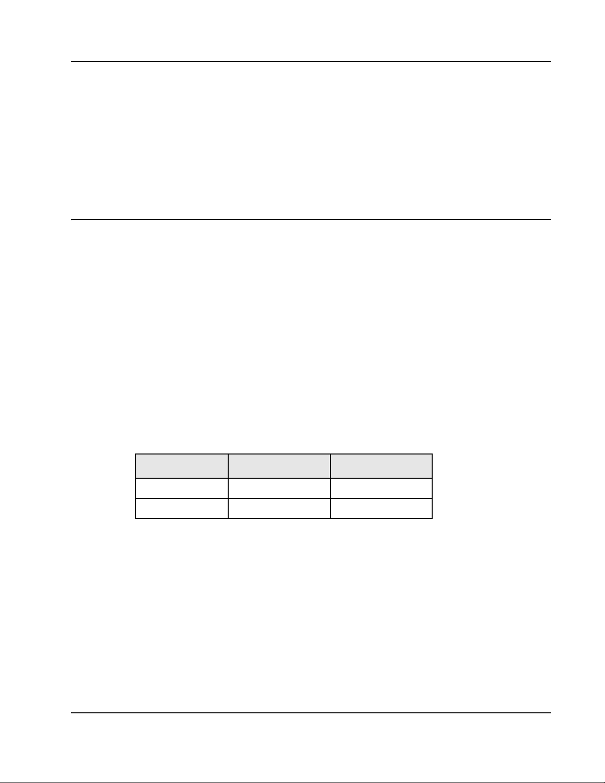
Non-differential Signal Notation
Non-differential signals are either active-low or active-high. An active-low signal has an active state of
logic 0 (or the lower voltage level), and is denoted by a lowercase “b”. An active-high signal has an
active state of logic 1 (or the higher voltage level), and is not denoted by a special character. The
following table illustrates the non-differential signal naming convention.
Object Size Notation
•Abyte is an 8-bit object.
•Aword is a 16-bit object.
•Adoubleword (Dword) is a 32-bit object.
Numeric Notation
• Hexadecimal numbers are denoted by the prefix 0x (for example, 0x04).
State Single-line signal Multi-line signal
Active low NAME_b NAMEn[3]
Active high NAME NAME[3]

About this Document4
Tsi350A User Manual
80D5000_MA001_08 Integrated Device Technology
www.idt.com
• Binary numbers are denoted by the prefix 0b (for example, 0b010).
• Registers that have multiple iterations are denoted by {x..y} in their names; where xis first register
and address, and yis the last register and address. For example, REG{0..1} indicates there are two
versions of the register at different addresses: REG0 and REG1.
Symbols
Document Status Information
• Advance – Contains information that is subject to change, and is available once prototypes are
released to customers.
• Preliminary – Contains information about a product that is near production-ready, and is revised as
required.
• Formal – Contains information about a final, customer-ready product, and is available once the
product is released to production.
Revision History
80D5000_MA001_08, Formal, September 2009
This document was rebranded as IDT. It does not include any technical changes.
80D5000_MA001_07, Formal, April 2008
This document supports the production version of the Tsi350A. The asynchronous mode functionality
was removed from this document. Information has been removed from “Secondary Clock Outputs” on
page 84 and pin 52 in “208-pin PQFP Pin List” on page 104 was changed from ASYNC_MODE to
VSS.
80D5000_MA001_06, Formal, January 2008
This document supported the production version of the Tsi350A. The Tsi350A is a performance
enhancement of the Tsi350 and there are no functional changes between the devices. All technical
information in this document applies to both the Tsi350 and the Tsi350A.
Tip
This symbol indicates a basic design concept or information considered helpful.
This symbol indicates important configuration information or suggestions.
This symbol indicates procedures or operating levels that may result in misuse or damage to
the device.

About this Document 5
Tsi350A User Manual
80D5000_MA001_08
Integrated Device Technology
www.idt.com
80D5000_MA001_05, Formal, August 2007
The changes to this document were minor and include register address clarifications in the register
chapter and a compliance list added to the overview chapter.
80D5000_MA001_04, Formal, March 2007
The following chapters were extensively edited:
•“Signals and Pinout” on page 93
•“Electrical Characteristics” on page 119
•“Package Information” on page 169

About this Document6
Tsi350A User Manual
80D5000_MA001_08 Integrated Device Technology
www.idt.com

Tsi350A User Manual
80D5000_MA001_08
Integrated Device Technology
www.idt.com
7
Contents
About this Document. . . . . . . . . . . . . . . . . . . . . . . . . . . . . . . . . . . . . . . . . . . . . . . . . . . . . 3
Scope . . . . . . . . . . . . . . . . . . . . . . . . . . . . . . . . . . . . . . . . . . . . . . . . . . . . . . . . . . . . . . . . . . . . . . . . . . . . . . . . . . . . . . . . . . 3
Document Conventions . . . . . . . . . . . . . . . . . . . . . . . . . . . . . . . . . . . . . . . . . . . . . . . . . . . . . . . . . . . . . . . . . . . . . . . . . . . . 3
Revision History . . . . . . . . . . . . . . . . . . . . . . . . . . . . . . . . . . . . . . . . . . . . . . . . . . . . . . . . . . . . . . . . . . . . . . . . . . . . . . . . . 4
1. Functional Overview . . . . . . . . . . . . . . . . . . . . . . . . . . . . . . . . . . . . . . . . . . . . . . . . 17
1.1 Overview of the Tsi350A. . . . . . . . . . . . . . . . . . . . . . . . . . . . . . . . . . . . . . . . . . . . . . . . . . . . . . . . . . . . . . . . . . . . 17
1.1.1 Features . . . . . . . . . . . . . . . . . . . . . . . . . . . . . . . . . . . . . . . . . . . . . . . . . . . . . . . . . . . . . . . . . . . . . . . . . 19
1.1.2 Compliance . . . . . . . . . . . . . . . . . . . . . . . . . . . . . . . . . . . . . . . . . . . . . . . . . . . . . . . . . . . . . . . . . . . . . . 20
1.2 Functional Description. . . . . . . . . . . . . . . . . . . . . . . . . . . . . . . . . . . . . . . . . . . . . . . . . . . . . . . . . . . . . . . . . . . . . . 20
1.2.1 PCI Interface . . . . . . . . . . . . . . . . . . . . . . . . . . . . . . . . . . . . . . . . . . . . . . . . . . . . . . . . . . . . . . . . . . . . . 20
1.2.2 JTAG Controller. . . . . . . . . . . . . . . . . . . . . . . . . . . . . . . . . . . . . . . . . . . . . . . . . . . . . . . . . . . . . . . . . . . 21
1.2.3 Hot Swap Interface. . . . . . . . . . . . . . . . . . . . . . . . . . . . . . . . . . . . . . . . . . . . . . . . . . . . . . . . . . . . . . . . . 21
1.3 Architecture . . . . . . . . . . . . . . . . . . . . . . . . . . . . . . . . . . . . . . . . . . . . . . . . . . . . . . . . . . . . . . . . . . . . . . . . . . . . . . 22
1.4 Data Path . . . . . . . . . . . . . . . . . . . . . . . . . . . . . . . . . . . . . . . . . . . . . . . . . . . . . . . . . . . . . . . . . . . . . . . . . . . . . . . . 22
1.4.1 Posted Write Queue . . . . . . . . . . . . . . . . . . . . . . . . . . . . . . . . . . . . . . . . . . . . . . . . . . . . . . . . . . . . . . . . 23
1.4.2 Delayed Transaction Queue . . . . . . . . . . . . . . . . . . . . . . . . . . . . . . . . . . . . . . . . . . . . . . . . . . . . . . . . . . 23
1.4.3 Read Data Queue . . . . . . . . . . . . . . . . . . . . . . . . . . . . . . . . . . . . . . . . . . . . . . . . . . . . . . . . . . . . . . . . . . 24
2. PCI Interface . . . . . . . . . . . . . . . . . . . . . . . . . . . . . . . . . . . . . . . . . . . . . . . . . . . . . . . 25
2.1 Transaction Types. . . . . . . . . . . . . . . . . . . . . . . . . . . . . . . . . . . . . . . . . . . . . . . . . . . . . . . . . . . . . . . . . . . . . . . . . . 25
2.2 Transaction Phases. . . . . . . . . . . . . . . . . . . . . . . . . . . . . . . . . . . . . . . . . . . . . . . . . . . . . . . . . . . . . . . . . . . . . . . . . 27
2.2.1 Address Phase . . . . . . . . . . . . . . . . . . . . . . . . . . . . . . . . . . . . . . . . . . . . . . . . . . . . . . . . . . . . . . . . . . . . 27
2.2.2 Data Phase . . . . . . . . . . . . . . . . . . . . . . . . . . . . . . . . . . . . . . . . . . . . . . . . . . . . . . . . . . . . . . . . . . . . . . . 28
2.3 Write Transactions . . . . . . . . . . . . . . . . . . . . . . . . . . . . . . . . . . . . . . . . . . . . . . . . . . . . . . . . . . . . . . . . . . . . . . . . . 28
2.3.1 Posted Write Transactions . . . . . . . . . . . . . . . . . . . . . . . . . . . . . . . . . . . . . . . . . . . . . . . . . . . . . . . . . . . 28
2.3.2 Memory Write and Invalidate Transactions. . . . . . . . . . . . . . . . . . . . . . . . . . . . . . . . . . . . . . . . . . . . . . 29
2.3.3 Delayed Write Transactions . . . . . . . . . . . . . . . . . . . . . . . . . . . . . . . . . . . . . . . . . . . . . . . . . . . . . . . . . . 30
2.3.4 Write Transaction Address Boundaries . . . . . . . . . . . . . . . . . . . . . . . . . . . . . . . . . . . . . . . . . . . . . . . . . 31
2.3.5 Buffering Multiple Write Transactions . . . . . . . . . . . . . . . . . . . . . . . . . . . . . . . . . . . . . . . . . . . . . . . . . 31
2.4 Read Transactions . . . . . . . . . . . . . . . . . . . . . . . . . . . . . . . . . . . . . . . . . . . . . . . . . . . . . . . . . . . . . . . . . . . . . . . . . 32
2.4.1 Calculating the Prefetch Count . . . . . . . . . . . . . . . . . . . . . . . . . . . . . . . . . . . . . . . . . . . . . . . . . . . . . . . 33
2.4.2 Prefetchable Read Transactions . . . . . . . . . . . . . . . . . . . . . . . . . . . . . . . . . . . . . . . . . . . . . . . . . . . . . . . 34
2.4.3 Non-Prefetchable Read Transactions. . . . . . . . . . . . . . . . . . . . . . . . . . . . . . . . . . . . . . . . . . . . . . . . . . . 34
2.4.4 Read Prefetch Address Boundaries . . . . . . . . . . . . . . . . . . . . . . . . . . . . . . . . . . . . . . . . . . . . . . . . . . . . 34
2.4.5 Delayed Read Requests . . . . . . . . . . . . . . . . . . . . . . . . . . . . . . . . . . . . . . . . . . . . . . . . . . . . . . . . . . . . . 35
2.5 Configuration Transactions . . . . . . . . . . . . . . . . . . . . . . . . . . . . . . . . . . . . . . . . . . . . . . . . . . . . . . . . . . . . . . . . . . 37
2.5.1 Type 0 Access to Tsi350A . . . . . . . . . . . . . . . . . . . . . . . . . . . . . . . . . . . . . . . . . . . . . . . . . . . . . . . . . . . 38
2.5.2 Type 1 to Type 0 Translation . . . . . . . . . . . . . . . . . . . . . . . . . . . . . . . . . . . . . . . . . . . . . . . . . . . . . . . . . 38
2.5.3 Type 1 to Type 1 Forwarding. . . . . . . . . . . . . . . . . . . . . . . . . . . . . . . . . . . . . . . . . . . . . . . . . . . . . . . . . 41

Contents8
Tsi350A User Manual
80D5000_MA001_08 Integrated Device Technology
www.idt.com
2.6 Transaction Termination . . . . . . . . . . . . . . . . . . . . . . . . . . . . . . . . . . . . . . . . . . . . . . . . . . . . . . . . . . . . . . . . . . . . 42
2.6.1 Master Termination Initiated by Tsi350A . . . . . . . . . . . . . . . . . . . . . . . . . . . . . . . . . . . . . . . . . . . . . . . 43
2.6.2 Master Abort Received by Tsi350A . . . . . . . . . . . . . . . . . . . . . . . . . . . . . . . . . . . . . . . . . . . . . . . . . . . 43
2.6.3 Target Termination Received by Tsi350A. . . . . . . . . . . . . . . . . . . . . . . . . . . . . . . . . . . . . . . . . . . . . . . 44
2.6.4 Target Termination Initiated by Tsi350A. . . . . . . . . . . . . . . . . . . . . . . . . . . . . . . . . . . . . . . . . . . . . . . . 46
3. Address Decoding. . . . . . . . . . . . . . . . . . . . . . . . . . . . . . . . . . . . . . . . . . . . . . . . . . .49
3.1 Overview of Address Decoding. . . . . . . . . . . . . . . . . . . . . . . . . . . . . . . . . . . . . . . . . . . . . . . . . . . . . . . . . . . . . . . 49
3.2 Address Ranges . . . . . . . . . . . . . . . . . . . . . . . . . . . . . . . . . . . . . . . . . . . . . . . . . . . . . . . . . . . . . . . . . . . . . . . . . . . 49
3.3 Address Decoding . . . . . . . . . . . . . . . . . . . . . . . . . . . . . . . . . . . . . . . . . . . . . . . . . . . . . . . . . . . . . . . . . . . . . . . . . 49
3.3.1 Base and Limit Address Registers. . . . . . . . . . . . . . . . . . . . . . . . . . . . . . . . . . . . . . . . . . . . . . . . . . . . . 50
3.3.2 ISA Mode. . . . . . . . . . . . . . . . . . . . . . . . . . . . . . . . . . . . . . . . . . . . . . . . . . . . . . . . . . . . . . . . . . . . . . . . 51
3.4 Memory Address Decoding. . . . . . . . . . . . . . . . . . . . . . . . . . . . . . . . . . . . . . . . . . . . . . . . . . . . . . . . . . . . . . . . . . 51
3.4.1 Memory-Mapped I/O Base and Limit Address Registers . . . . . . . . . . . . . . . . . . . . . . . . . . . . . . . . . . . 52
3.4.2 Prefetchable Memory Base and Limit Address Registers. . . . . . . . . . . . . . . . . . . . . . . . . . . . . . . . . . . 53
3.4.3 Prefetchable Memory 64-Bit Addressing Registers . . . . . . . . . . . . . . . . . . . . . . . . . . . . . . . . . . . . . . . 54
3.5 VGA Support . . . . . . . . . . . . . . . . . . . . . . . . . . . . . . . . . . . . . . . . . . . . . . . . . . . . . . . . . . . . . . . . . . . . . . . . . . . . 55
3.5.1 VGA Mode . . . . . . . . . . . . . . . . . . . . . . . . . . . . . . . . . . . . . . . . . . . . . . . . . . . . . . . . . . . . . . . . . . . . . . 55
3.5.2 VGA Snoop Mode. . . . . . . . . . . . . . . . . . . . . . . . . . . . . . . . . . . . . . . . . . . . . . . . . . . . . . . . . . . . . . . . . 56
4. Transaction Ordering . . . . . . . . . . . . . . . . . . . . . . . . . . . . . . . . . . . . . . . . . . . . . . . .57
4.2 Transaction Governed by Ordering Rules . . . . . . . . . . . . . . . . . . . . . . . . . . . . . . . . . . . . . . . . . . . . . . . . . . . . . . . 57
4.3 General Ordering Guidelines. . . . . . . . . . . . . . . . . . . . . . . . . . . . . . . . . . . . . . . . . . . . . . . . . . . . . . . . . . . . . . . . . 58
4.3.1 Ordering Rules. . . . . . . . . . . . . . . . . . . . . . . . . . . . . . . . . . . . . . . . . . . . . . . . . . . . . . . . . . . . . . . . . . . . 59
5. Error Handling . . . . . . . . . . . . . . . . . . . . . . . . . . . . . . . . . . . . . . . . . . . . . . . . . . . . . .61
5.2 Address Parity Errors. . . . . . . . . . . . . . . . . . . . . . . . . . . . . . . . . . . . . . . . . . . . . . . . . . . . . . . . . . . . . . . . . . . . . . . 61
5.3 Data Parity Errors . . . . . . . . . . . . . . . . . . . . . . . . . . . . . . . . . . . . . . . . . . . . . . . . . . . . . . . . . . . . . . . . . . . . . . . . . 62
5.3.1 Configuration Write Transactions to Tsi350A Configuration Space. . . . . . . . . . . . . . . . . . . . . . . . . . . 62
5.3.2 Read Transactions . . . . . . . . . . . . . . . . . . . . . . . . . . . . . . . . . . . . . . . . . . . . . . . . . . . . . . . . . . . . . . . . . 62
5.3.3 Delayed Write Transactions. . . . . . . . . . . . . . . . . . . . . . . . . . . . . . . . . . . . . . . . . . . . . . . . . . . . . . . . . . 63
5.3.4 Posted Write Transactions . . . . . . . . . . . . . . . . . . . . . . . . . . . . . . . . . . . . . . . . . . . . . . . . . . . . . . . . . . . 65
5.4 System Error (SERR_b) Reporting . . . . . . . . . . . . . . . . . . . . . . . . . . . . . . . . . . . . . . . . . . . . . . . . . . . . . . . . . . . . 66
6. Exclusive Access. . . . . . . . . . . . . . . . . . . . . . . . . . . . . . . . . . . . . . . . . . . . . . . . . . . .69
6.1 Concurrent Locks. . . . . . . . . . . . . . . . . . . . . . . . . . . . . . . . . . . . . . . . . . . . . . . . . . . . . . . . . . . . . . . . . . . . . . . . . . 69
6.2 Acquiring Exclusive Access Across the Tsi350A . . . . . . . . . . . . . . . . . . . . . . . . . . . . . . . . . . . . . . . . . . . . . . . . . 69
6.3 Ending Exclusive Access. . . . . . . . . . . . . . . . . . . . . . . . . . . . . . . . . . . . . . . . . . . . . . . . . . . . . . . . . . . . . . . . . . . . 70
7. PCI Bus Arbitration . . . . . . . . . . . . . . . . . . . . . . . . . . . . . . . . . . . . . . . . . . . . . . . . . .73
7.1 Overview . . . . . . . . . . . . . . . . . . . . . . . . . . . . . . . . . . . . . . . . . . . . . . . . . . . . . . . . . . . . . . . . . . . . . . . . . . . . . . . . 73
7.2 Primary PCI Bus Arbitration. . . . . . . . . . . . . . . . . . . . . . . . . . . . . . . . . . . . . . . . . . . . . . . . . . . . . . . . . . . . . . . . . 73
7.3 Secondary PCI Bus Arbitration . . . . . . . . . . . . . . . . . . . . . . . . . . . . . . . . . . . . . . . . . . . . . . . . . . . . . . . . . . . . . . 74
7.3.1 Secondary Bus Arbitration Using the Internal Arbiter . . . . . . . . . . . . . . . . . . . . . . . . . . . . . . . . . . . . . 74
7.3.2 Secondary Bus Arbitration Using an External Arbiter . . . . . . . . . . . . . . . . . . . . . . . . . . . . . . . . . . . . . 75
7.4 Bus Parking . . . . . . . . . . . . . . . . . . . . . . . . . . . . . . . . . . . . . . . . . . . . . . . . . . . . . . . . . . . . . . . . . . . . . . . . . . . . . . 75

Tsi350A User Manual
80D5000_MA001_08
Integrated Device Technology
www.idt.com
Contents 9
8. General Purpose I/O. . . . . . . . . . . . . . . . . . . . . . . . . . . . . . . . . . . . . . . . . . . . . . . . . 77
8.1 Overview . . . . . . . . . . . . . . . . . . . . . . . . . . . . . . . . . . . . . . . . . . . . . . . . . . . . . . . . . . . . . . . . . . . . . . . . . . . . . . . . 77
8.2 GPIO Control Registers . . . . . . . . . . . . . . . . . . . . . . . . . . . . . . . . . . . . . . . . . . . . . . . . . . . . . . . . . . . . . . . . . . . . . 77
8.3 Secondary Clock Control. . . . . . . . . . . . . . . . . . . . . . . . . . . . . . . . . . . . . . . . . . . . . . . . . . . . . . . . . . . . . . . . . . . . 78
8.4 Live Insertion. . . . . . . . . . . . . . . . . . . . . . . . . . . . . . . . . . . . . . . . . . . . . . . . . . . . . . . . . . . . . . . . . . . . . . . . . . . . . 80
8.5 CompactPCI Hot-swap Support. . . . . . . . . . . . . . . . . . . . . . . . . . . . . . . . . . . . . . . . . . . . . . . . . . . . . . . . . . . . . . . 80
9. Clocks . . . . . . . . . . . . . . . . . . . . . . . . . . . . . . . . . . . . . . . . . . . . . . . . . . . . . . . . . . . . 83
9.1 Overview . . . . . . . . . . . . . . . . . . . . . . . . . . . . . . . . . . . . . . . . . . . . . . . . . . . . . . . . . . . . . . . . . . . . . . . . . . . . . . . . 83
9.2 Primary and Secondary Clock Inputs. . . . . . . . . . . . . . . . . . . . . . . . . . . . . . . . . . . . . . . . . . . . . . . . . . . . . . . . . . . 83
9.2.1 Synchronous Secondary Clock Input. . . . . . . . . . . . . . . . . . . . . . . . . . . . . . . . . . . . . . . . . . . . . . . . . . . 83
9.2.2 Asynchronous Secondary Clock Input. . . . . . . . . . . . . . . . . . . . . . . . . . . . . . . . . . . . . . . . . . . . . . . . . . 83
9.3 Secondary Clock Outputs. . . . . . . . . . . . . . . . . . . . . . . . . . . . . . . . . . . . . . . . . . . . . . . . . . . . . . . . . . . . . . . . . . . . 84
9.3.1 Running the Secondary Clock Faster than the Primary Clock. . . . . . . . . . . . . . . . . . . . . . . . . . . . . . . . 84
10. PCI Power Management. . . . . . . . . . . . . . . . . . . . . . . . . . . . . . . . . . . . . . . . . . . . . . 85
11. Reset . . . . . . . . . . . . . . . . . . . . . . . . . . . . . . . . . . . . . . . . . . . . . . . . . . . . . . . . . . . . . 87
11.1 Primary Interface Reset . . . . . . . . . . . . . . . . . . . . . . . . . . . . . . . . . . . . . . . . . . . . . . . . . . . . . . . . . . . . . . . . . . . . . 87
11.2 Secondary Interface Reset . . . . . . . . . . . . . . . . . . . . . . . . . . . . . . . . . . . . . . . . . . . . . . . . . . . . . . . . . . . . . . . . . . . 87
11.3 Chip Reset . . . . . . . . . . . . . . . . . . . . . . . . . . . . . . . . . . . . . . . . . . . . . . . . . . . . . . . . . . . . . . . . . . . . . . . . . . . . . . . 88
12. JTAG Module . . . . . . . . . . . . . . . . . . . . . . . . . . . . . . . . . . . . . . . . . . . . . . . . . . . . . . 89
12.2 JTAG Signal Pins. . . . . . . . . . . . . . . . . . . . . . . . . . . . . . . . . . . . . . . . . . . . . . . . . . . . . . . . . . . . . . . . . . . . . . . . . . 89
12.3 Test Access Port (TAP) Controller. . . . . . . . . . . . . . . . . . . . . . . . . . . . . . . . . . . . . . . . . . . . . . . . . . . . . . . . . . . . . 90
12.3.1 Instruction Register . . . . . . . . . . . . . . . . . . . . . . . . . . . . . . . . . . . . . . . . . . . . . . . . . . . . . . . . . . . . . . . . 90
12.3.2 Bypass Register . . . . . . . . . . . . . . . . . . . . . . . . . . . . . . . . . . . . . . . . . . . . . . . . . . . . . . . . . . . . . . . . . . . 90
12.3.3 Boundary-Scan Register. . . . . . . . . . . . . . . . . . . . . . . . . . . . . . . . . . . . . . . . . . . . . . . . . . . . . . . . . . . . . 91
12.4 Initialization . . . . . . . . . . . . . . . . . . . . . . . . . . . . . . . . . . . . . . . . . . . . . . . . . . . . . . . . . . . . . . . . . . . . . . . . . . . . . . 91
13. Signals and Pinout. . . . . . . . . . . . . . . . . . . . . . . . . . . . . . . . . . . . . . . . . . . . . . . . . . 93
13.2 Signals . . . . . . . . . . . . . . . . . . . . . . . . . . . . . . . . . . . . . . . . . . . . . . . . . . . . . . . . . . . . . . . . . . . . . . . . . . . . . . . . . . 95
13.2.1 Primary PCI Bus Interface Signals . . . . . . . . . . . . . . . . . . . . . . . . . . . . . . . . . . . . . . . . . . . . . . . . . . . . 95
13.2.2 Secondary PCI Bus Interface Signals . . . . . . . . . . . . . . . . . . . . . . . . . . . . . . . . . . . . . . . . . . . . . . . . . . 97
13.2.3 Secondary Bus Arbitration Signals . . . . . . . . . . . . . . . . . . . . . . . . . . . . . . . . . . . . . . . . . . . . . . . . . . . . 99
13.2.4 Clock Signals . . . . . . . . . . . . . . . . . . . . . . . . . . . . . . . . . . . . . . . . . . . . . . . . . . . . . . . . . . . . . . . . . . . . 100
13.2.5 Reset Signals . . . . . . . . . . . . . . . . . . . . . . . . . . . . . . . . . . . . . . . . . . . . . . . . . . . . . . . . . . . . . . . . . . . . 101
13.2.6 Miscellaneous Signals . . . . . . . . . . . . . . . . . . . . . . . . . . . . . . . . . . . . . . . . . . . . . . . . . . . . . . . . . . . . . 101
13.2.7 JTAG Signals . . . . . . . . . . . . . . . . . . . . . . . . . . . . . . . . . . . . . . . . . . . . . . . . . . . . . . . . . . . . . . . . . . . . 103
13.2.8 Power and Ground Pins . . . . . . . . . . . . . . . . . . . . . . . . . . . . . . . . . . . . . . . . . . . . . . . . . . . . . . . . . . . . 103
13.3 Pinout . . . . . . . . . . . . . . . . . . . . . . . . . . . . . . . . . . . . . . . . . . . . . . . . . . . . . . . . . . . . . . . . . . . . . . . . . . . . . . . . . . 104
13.3.1 208-pin PQFP Pin List. . . . . . . . . . . . . . . . . . . . . . . . . . . . . . . . . . . . . . . . . . . . . . . . . . . . . . . . . . . . . 104
13.3.2 256-pin PBGA Pin List . . . . . . . . . . . . . . . . . . . . . . . . . . . . . . . . . . . . . . . . . . . . . . . . . . . . . . . . . . . . 112

Contents10
Tsi350A User Manual
80D5000_MA001_08 Integrated Device Technology
www.idt.com
14. Electrical Characteristics . . . . . . . . . . . . . . . . . . . . . . . . . . . . . . . . . . . . . . . . . . . .119
14.1 Absolute Maximum Ratings . . . . . . . . . . . . . . . . . . . . . . . . . . . . . . . . . . . . . . . . . . . . . . . . . . . . . . . . . . . . . . . . 119
14.2 Recommended Operating Conditions . . . . . . . . . . . . . . . . . . . . . . . . . . . . . . . . . . . . . . . . . . . . . . . . . . . . . . . . . 119
14.3 Power Characteristics . . . . . . . . . . . . . . . . . . . . . . . . . . . . . . . . . . . . . . . . . . . . . . . . . . . . . . . . . . . . . . . . . . . . . 120
14.4 Power Supply Sequencing . . . . . . . . . . . . . . . . . . . . . . . . . . . . . . . . . . . . . . . . . . . . . . . . . . . . . . . . . . . . . . . . . . 120
14.5 DC Specifications . . . . . . . . . . . . . . . . . . . . . . . . . . . . . . . . . . . . . . . . . . . . . . . . . . . . . . . . . . . . . . . . . . . . . . . . 120
14.6 AC Timing Specifications . . . . . . . . . . . . . . . . . . . . . . . . . . . . . . . . . . . . . . . . . . . . . . . . . . . . . . . . . . . . . . . . . . 122
15. Registers . . . . . . . . . . . . . . . . . . . . . . . . . . . . . . . . . . . . . . . . . . . . . . . . . . . . . . . . .125
15.1.1 Reserved Register Addresses and Fields. . . . . . . . . . . . . . . . . . . . . . . . . . . . . . . . . . . . . . . . . . . . . . . 127
15.2 PCI-to-PCI Bridge Standard Configuration Registers. . . . . . . . . . . . . . . . . . . . . . . . . . . . . . . . . . . . . . . . . . . . . 128
15.2.1 Vendor ID Register—Offset 0x00 . . . . . . . . . . . . . . . . . . . . . . . . . . . . . . . . . . . . . . . . . . . . . . . . . . . . 128
15.2.2 Device ID Register—Offset 0x00 . . . . . . . . . . . . . . . . . . . . . . . . . . . . . . . . . . . . . . . . . . . . . . . . . . . . 128
15.2.3 Primary Command Register—Offset 0x04 . . . . . . . . . . . . . . . . . . . . . . . . . . . . . . . . . . . . . . . . . . . . . 129
15.2.4 Primary Status Register—Offset 0x04. . . . . . . . . . . . . . . . . . . . . . . . . . . . . . . . . . . . . . . . . . . . . . . . . 131
15.2.5 Revision ID Register—Offset 0x08. . . . . . . . . . . . . . . . . . . . . . . . . . . . . . . . . . . . . . . . . . . . . . . . . . . 133
15.2.6 Programming Interface Register—Offset 0x08. . . . . . . . . . . . . . . . . . . . . . . . . . . . . . . . . . . . . . . . . . 133
15.2.7 Subclass Code Register—Offset 0x08. . . . . . . . . . . . . . . . . . . . . . . . . . . . . . . . . . . . . . . . . . . . . . . . . 133
15.2.8 Base Class Code Register—Offset 0x08. . . . . . . . . . . . . . . . . . . . . . . . . . . . . . . . . . . . . . . . . . . . . . . 134
15.2.9 Cache Line Size Register—Offset 0x0C. . . . . . . . . . . . . . . . . . . . . . . . . . . . . . . . . . . . . . . . . . . . . . . 135
15.2.10 Primary Latency Timer Register—Offset 0x0C . . . . . . . . . . . . . . . . . . . . . . . . . . . . . . . . . . . . . . . . . 135
15.2.11 Header Type Register—Offset 0x0C. . . . . . . . . . . . . . . . . . . . . . . . . . . . . . . . . . . . . . . . . . . . . . . . . . 135
15.2.12 Primary Bus Number Register—Offset 0x18 . . . . . . . . . . . . . . . . . . . . . . . . . . . . . . . . . . . . . . . . . . . 136
15.2.13 Secondary Bus Number Register—Offset 0x18 . . . . . . . . . . . . . . . . . . . . . . . . . . . . . . . . . . . . . . . . . 136
15.2.14 Subordinate Bus Number Register—Offset 0x18 . . . . . . . . . . . . . . . . . . . . . . . . . . . . . . . . . . . . . . . . 137
15.2.15 Secondary Latency Timer Register—Offset 0x18. . . . . . . . . . . . . . . . . . . . . . . . . . . . . . . . . . . . . . . . 137
15.2.16 I/O Base Address Register—Offset 0x1C. . . . . . . . . . . . . . . . . . . . . . . . . . . . . . . . . . . . . . . . . . . . . . 138
15.2.17 I/O Limit Address Register—Offset 0x1C . . . . . . . . . . . . . . . . . . . . . . . . . . . . . . . . . . . . . . . . . . . . . 138
15.2.18 Secondary Status Register—Offset 0x1C . . . . . . . . . . . . . . . . . . . . . . . . . . . . . . . . . . . . . . . . . . . . . . 139
15.2.19 Memory Base Address Register—Offset 0x20 . . . . . . . . . . . . . . . . . . . . . . . . . . . . . . . . . . . . . . . . . . 141
15.2.20 Memory Limit Address Register—Offset 0x20 . . . . . . . . . . . . . . . . . . . . . . . . . . . . . . . . . . . . . . . . . 141
15.2.21 Prefetchable Memory Base Address Register—Offset 0x24 . . . . . . . . . . . . . . . . . . . . . . . . . . . . . . . 142
15.2.22 Prefetchable Memory Limit Address Register—Offset 0x24 . . . . . . . . . . . . . . . . . . . . . . . . . . . . . . . 142
15.2.23 Prefetchable Memory Base Address Upper 32 Bits Register—Offset 0x28. . . . . . . . . . . . . . . . . . . . 143
15.2.24 Prefetchable Memory Limit Address Upper 32 Bits Register—Offset 0x2C. . . . . . . . . . . . . . . . . . . 144
15.2.25 I/O Base Address Upper 16 Bits Register—Offset 0x30 . . . . . . . . . . . . . . . . . . . . . . . . . . . . . . . . . . 145
15.2.26 I/O Limit Address Upper 16 Bits Register—Offset 0x30 . . . . . . . . . . . . . . . . . . . . . . . . . . . . . . . . . . 145
15.2.27 ECP Pointer Register—Offset 0x34 . . . . . . . . . . . . . . . . . . . . . . . . . . . . . . . . . . . . . . . . . . . . . . . . . . 146
15.2.28 Interrupt Pin Register—Offset 0x3C. . . . . . . . . . . . . . . . . . . . . . . . . . . . . . . . . . . . . . . . . . . . . . . . . . 146
15.2.29 Bridge Control Register—Offset 0x3C . . . . . . . . . . . . . . . . . . . . . . . . . . . . . . . . . . . . . . . . . . . . . . . . 147
15.3 Device-Specific Configuration Registers . . . . . . . . . . . . . . . . . . . . . . . . . . . . . . . . . . . . . . . . . . . . . . . . . . . . . . 151
15.3.1 Chip Control Register—Offset 0x40. . . . . . . . . . . . . . . . . . . . . . . . . . . . . . . . . . . . . . . . . . . . . . . . . . 152
15.3.2 Diagnostic Control Register—Offset 0x40 . . . . . . . . . . . . . . . . . . . . . . . . . . . . . . . . . . . . . . . . . . . . . 153
15.3.3 Arbiter Control Register—Offset 0x40 . . . . . . . . . . . . . . . . . . . . . . . . . . . . . . . . . . . . . . . . . . . . . . . . 154
15.3.4 Read Transaction Control Register— Offset 0x44 . . . . . . . . . . . . . . . . . . . . . . . . . . . . . . . . . . . . . . . 155

Tsi350A User Manual
80D5000_MA001_08
Integrated Device Technology
www.idt.com
Contents 11
15.3.5 P_SERR_b Event Disable Register—Offset 0x64. . . . . . . . . . . . . . . . . . . . . . . . . . . . . . . . . . . . . . . . 156
15.3.6 GPIO Output Data Register—Offset 0x64. . . . . . . . . . . . . . . . . . . . . . . . . . . . . . . . . . . . . . . . . . . . . . 157
15.3.7 GPIO Output Enable Control Register—Offset 0x64 . . . . . . . . . . . . . . . . . . . . . . . . . . . . . . . . . . . . . 158
15.3.8 GPIO Input Data Register—Offset 0x64. . . . . . . . . . . . . . . . . . . . . . . . . . . . . . . . . . . . . . . . . . . . . . . 158
15.3.9 Secondary Clock Control Register—Offset 0x68 . . . . . . . . . . . . . . . . . . . . . . . . . . . . . . . . . . . . . . . . 159
15.3.10 P_SERR_b Status Register—Offset 0x68 . . . . . . . . . . . . . . . . . . . . . . . . . . . . . . . . . . . . . . . . . . . . . . 160
15.3.11 Capability ID Register—Offset 0xDC. . . . . . . . . . . . . . . . . . . . . . . . . . . . . . . . . . . . . . . . . . . . . . . . . 161
15.3.12 Next Item Pointer Register—Offset 0xDD . . . . . . . . . . . . . . . . . . . . . . . . . . . . . . . . . . . . . . . . . . . . . 161
15.3.13 Power Management Capabilities Register—Offset 0xDE. . . . . . . . . . . . . . . . . . . . . . . . . . . . . . . . . . 162
15.3.14 Power Management Control and Status Register—Offset 0xE0 . . . . . . . . . . . . . . . . . . . . . . . . . . . . . 163
15.3.15 PPB Support Extensions Registers—Offset 0xE2. . . . . . . . . . . . . . . . . . . . . . . . . . . . . . . . . . . . . . . . 164
15.3.16 Data Register—Offset 0xE3. . . . . . . . . . . . . . . . . . . . . . . . . . . . . . . . . . . . . . . . . . . . . . . . . . . . . . . . . 164
15.3.17 HS Capability ID Register— Offset 0xE4. . . . . . . . . . . . . . . . . . . . . . . . . . . . . . . . . . . . . . . . . . . . . . 165
15.3.18 HS Next Item Pointer Register— Offset 0xE5 . . . . . . . . . . . . . . . . . . . . . . . . . . . . . . . . . . . . . . . . . . 165
15.3.19 HS Control Status Register— Offset 0xE6 . . . . . . . . . . . . . . . . . . . . . . . . . . . . . . . . . . . . . . . . . . . . . 166
A. Package Information . . . . . . . . . . . . . . . . . . . . . . . . . . . . . . . . . . . . . . . . . . . . . . . 169
A.1 Package Characteristics . . . . . . . . . . . . . . . . . . . . . . . . . . . . . . . . . . . . . . . . . . . . . . . . . . . . . . . . . . . . . . . . . . . . 169
A.1.1 208-pin PQFP Package . . . . . . . . . . . . . . . . . . . . . . . . . . . . . . . . . . . . . . . . . . . . . . . . . . . . . . . . . . . . 169
A.1.2 256-pin PBGA Package . . . . . . . . . . . . . . . . . . . . . . . . . . . . . . . . . . . . . . . . . . . . . . . . . . . . . . . . . . . . 172
A.2 Thermal Characteristics . . . . . . . . . . . . . . . . . . . . . . . . . . . . . . . . . . . . . . . . . . . . . . . . . . . . . . . . . . . . . . . . . . . . 174
A.2.1 Junction-to-Ambient Thermal Characteristics (Theta ja) . . . . . . . . . . . . . . . . . . . . . . . . . . . . . . . . . . 174
A.2.2 System-level Characteristics . . . . . . . . . . . . . . . . . . . . . . . . . . . . . . . . . . . . . . . . . . . . . . . . . . . . . . . . 175
A.2.3 Example on Thermal Data Usage . . . . . . . . . . . . . . . . . . . . . . . . . . . . . . . . . . . . . . . . . . . . . . . . . . . . 175
B. Ordering Information . . . . . . . . . . . . . . . . . . . . . . . . . . . . . . . . . . . . . . . . . . . . . . . 177
B.1 Ordering Information . . . . . . . . . . . . . . . . . . . . . . . . . . . . . . . . . . . . . . . . . . . . . . . . . . . . . . . . . . . . . . . . . . . . . . 177

Contents12
Tsi350A User Manual
80D5000_MA001_08 Integrated Device Technology
www.idt.com

Tsi350A User Manual
80D5000_MA001_08
Integrated Device Technology
www.idt.com
13
Figures
Figure 1: Block Diagram. . . . . . . . . . . . . . . . . . . . . . . . . . . . . . . . . . . . . . . . . . . . . . . . . . . . . . . . . . . . . . . . . . . . . . . . . . . . . 18
Figure 2: System Block Diagram . . . . . . . . . . . . . . . . . . . . . . . . . . . . . . . . . . . . . . . . . . . . . . . . . . . . . . . . . . . . . . . . . . . . . . 19
Figure 3: Tsi350A Downstream Data Path. . . . . . . . . . . . . . . . . . . . . . . . . . . . . . . . . . . . . . . . . . . . . . . . . . . . . . . . . . . . . . . 23
Figure 4: Type 0 Configuration Transaction. . . . . . . . . . . . . . . . . . . . . . . . . . . . . . . . . . . . . . . . . . . . . . . . . . . . . . . . . . . . . . 37
Figure 5: Type 1 Configuration Transaction. . . . . . . . . . . . . . . . . . . . . . . . . . . . . . . . . . . . . . . . . . . . . . . . . . . . . . . . . . . . . . 37
Figure 6: Clock Mask Load and Shift Timing . . . . . . . . . . . . . . . . . . . . . . . . . . . . . . . . . . . . . . . . . . . . . . . . . . . . . . . . . . . . 79
Figure 7: PCI Signal Timing Measurement Conditions . . . . . . . . . . . . . . . . . . . . . . . . . . . . . . . . . . . . . . . . . . . . . . . . . . . . 122
Figure 8: 208-pin PQFP Package Diagram - Top View . . . . . . . . . . . . . . . . . . . . . . . . . . . . . . . . . . . . . . . . . . . . . . . . . . . . 170
Figure 9: 208-pin PQFP Package Diagram - Side View. . . . . . . . . . . . . . . . . . . . . . . . . . . . . . . . . . . . . . . . . . . . . . . . . . . . 171
Figure 10: 208-pin PQFP Package Diagram - Side View. . . . . . . . . . . . . . . . . . . . . . . . . . . . . . . . . . . . . . . . . . . . . . . . . . . . 171
Figure 11: 256-pin PBGA Package Diagram - Top View . . . . . . . . . . . . . . . . . . . . . . . . . . . . . . . . . . . . . . . . . . . . . . . . . . . 172
Figure 12: 256-pin PBGA Package Diagram - Bottom View. . . . . . . . . . . . . . . . . . . . . . . . . . . . . . . . . . . . . . . . . . . . . . . . . 173
Figure 13: 256-pin PBGA Package Diagram - Side View . . . . . . . . . . . . . . . . . . . . . . . . . . . . . . . . . . . . . . . . . . . . . . . . . . . 173

Figures14
Tsi350A User Manual
80D5000_MA001_08 Integrated Device Technology
www.idt.com

Tsi350A User Manual
80D5000_MA001_08
Integrated Device Technology
www.idt.com
15
Tables
Table 1: Tsi350A PCI Transactions. . . . . . . . . . . . . . . . . . . . . . . . . . . . . . . . . . . . . . . . . . . . . . . . . . . . . . . . . . . . . . . . . . . . 26
Table 2: Write Transaction Address Boundaries . . . . . . . . . . . . . . . . . . . . . . . . . . . . . . . . . . . . . . . . . . . . . . . . . . . . . . . . . . 31
Table 3: Read Transaction Prefetching . . . . . . . . . . . . . . . . . . . . . . . . . . . . . . . . . . . . . . . . . . . . . . . . . . . . . . . . . . . . . . . . . 32
Table 4: Read Prefetch Address Boundaries . . . . . . . . . . . . . . . . . . . . . . . . . . . . . . . . . . . . . . . . . . . . . . . . . . . . . . . . . . . . . 35
Table 5: Device Number to IDSEL S_AD Pin Mapping . . . . . . . . . . . . . . . . . . . . . . . . . . . . . . . . . . . . . . . . . . . . . . . . . . . . 39
Table 6: Tsi350A Response to Delayed Write Transaction . . . . . . . . . . . . . . . . . . . . . . . . . . . . . . . . . . . . . . . . . . . . . . . . . . 44
Table 7: Tsi350A Response to Posted Write Termination. . . . . . . . . . . . . . . . . . . . . . . . . . . . . . . . . . . . . . . . . . . . . . . . . . . 45
Table 8: Tsi350A Response to Delayed Read Target Termination . . . . . . . . . . . . . . . . . . . . . . . . . . . . . . . . . . . . . . . . . . . . 46
Table 9: Summary of Transaction Ordering. . . . . . . . . . . . . . . . . . . . . . . . . . . . . . . . . . . . . . . . . . . . . . . . . . . . . . . . . . . . . . 59
Table 10: Clock Mask Data Format . . . . . . . . . . . . . . . . . . . . . . . . . . . . . . . . . . . . . . . . . . . . . . . . . . . . . . . . . . . . . . . . . . . . . 79
Table 11: Tsi350A Hot-Swap Mode Selection . . . . . . . . . . . . . . . . . . . . . . . . . . . . . . . . . . . . . . . . . . . . . . . . . . . . . . . . . . . . 81
Table 12: Tsi350A S_CLK_O clock outputs . . . . . . . . . . . . . . . . . . . . . . . . . . . . . . . . . . . . . . . . . . . . . . . . . . . . . . . . . . . . . . 84
Table 13: Power Management Transitions. . . . . . . . . . . . . . . . . . . . . . . . . . . . . . . . . . . . . . . . . . . . . . . . . . . . . . . . . . . . . . . . 85
Table 14: JTAG Signal Pins. . . . . . . . . . . . . . . . . . . . . . . . . . . . . . . . . . . . . . . . . . . . . . . . . . . . . . . . . . . . . . . . . . . . . . . . . . . 89
Table 15: JTAG Instructions . . . . . . . . . . . . . . . . . . . . . . . . . . . . . . . . . . . . . . . . . . . . . . . . . . . . . . . . . . . . . . . . . . . . . . . . . . 90
Table 16: Tsi350A Signal Pins. . . . . . . . . . . . . . . . . . . . . . . . . . . . . . . . . . . . . . . . . . . . . . . . . . . . . . . . . . . . . . . . . . . . . . . . . 93
Table 17: Tsi350A Signal Types . . . . . . . . . . . . . . . . . . . . . . . . . . . . . . . . . . . . . . . . . . . . . . . . . . . . . . . . . . . . . . . . . . . . . . . 94
Table 18: Primary PCI Bus Interface Signals. . . . . . . . . . . . . . . . . . . . . . . . . . . . . . . . . . . . . . . . . . . . . . . . . . . . . . . . . . . . . . 95
Table 19: Secondary PCI Bus Interface Signals. . . . . . . . . . . . . . . . . . . . . . . . . . . . . . . . . . . . . . . . . . . . . . . . . . . . . . . . . . . . 97
Table 20: Secondary PCI Bus Arbitration Signals. . . . . . . . . . . . . . . . . . . . . . . . . . . . . . . . . . . . . . . . . . . . . . . . . . . . . . . . . . 99
Table 21: Clock Signals . . . . . . . . . . . . . . . . . . . . . . . . . . . . . . . . . . . . . . . . . . . . . . . . . . . . . . . . . . . . . . . . . . . . . . . . . . . . . 100
Table 22: Tsi350A Reset Signals . . . . . . . . . . . . . . . . . . . . . . . . . . . . . . . . . . . . . . . . . . . . . . . . . . . . . . . . . . . . . . . . . . . . . . 101
Table 23: Tsi350A Miscellaneous Signals. . . . . . . . . . . . . . . . . . . . . . . . . . . . . . . . . . . . . . . . . . . . . . . . . . . . . . . . . . . . . . . 101
Table 24: JTAG Signals . . . . . . . . . . . . . . . . . . . . . . . . . . . . . . . . . . . . . . . . . . . . . . . . . . . . . . . . . . . . . . . . . . . . . . . . . . . . . 103
Table 25: Power and Ground Pins . . . . . . . . . . . . . . . . . . . . . . . . . . . . . . . . . . . . . . . . . . . . . . . . . . . . . . . . . . . . . . . . . . . . . 103
Table 26: Tsi350A 208 Pin List . . . . . . . . . . . . . . . . . . . . . . . . . . . . . . . . . . . . . . . . . . . . . . . . . . . . . . . . . . . . . . . . . . . . . . . 104
Table 27: Tsi350A 256 Pin List . . . . . . . . . . . . . . . . . . . . . . . . . . . . . . . . . . . . . . . . . . . . . . . . . . . . . . . . . . . . . . . . . . . . . . . 112
Table 28: Tsi350A 256 Pin List - Power, Ground, and Reserved . . . . . . . . . . . . . . . . . . . . . . . . . . . . . . . . . . . . . . . . . . . . . 117
Table 29: Absolute Maximum Ratings. . . . . . . . . . . . . . . . . . . . . . . . . . . . . . . . . . . . . . . . . . . . . . . . . . . . . . . . . . . . . . . . . . 119
Table 30: Recommended Operating Conditions . . . . . . . . . . . . . . . . . . . . . . . . . . . . . . . . . . . . . . . . . . . . . . . . . . . . . . . . . . 119
Table 31: Power Characteristics. . . . . . . . . . . . . . . . . . . . . . . . . . . . . . . . . . . . . . . . . . . . . . . . . . . . . . . . . . . . . . . . . . . . . . . 120
Table 32: Tsi350A DC Specifications . . . . . . . . . . . . . . . . . . . . . . . . . . . . . . . . . . . . . . . . . . . . . . . . . . . . . . . . . . . . . . . . . . 120
Table 33: 33 MHz PCI Signal Timing . . . . . . . . . . . . . . . . . . . . . . . . . . . . . . . . . . . . . . . . . . . . . . . . . . . . . . . . . . . . . . . . . . 123
Table 34: 66 MHz PCI Signal Timing . . . . . . . . . . . . . . . . . . . . . . . . . . . . . . . . . . . . . . . . . . . . . . . . . . . . . . . . . . . . . . . . . . 123
Table 35: Tsi350A Configuration Space . . . . . . . . . . . . . . . . . . . . . . . . . . . . . . . . . . . . . . . . . . . . . . . . . . . . . . . . . . . . . . . . 125
Table 36: Register Access Types . . . . . . . . . . . . . . . . . . . . . . . . . . . . . . . . . . . . . . . . . . . . . . . . . . . . . . . . . . . . . . . . . . . . . . 127
Table 37: PQFP Symbol Values. . . . . . . . . . . . . . . . . . . . . . . . . . . . . . . . . . . . . . . . . . . . . . . . . . . . . . . . . . . . . . . . . . . . . . . 169
Table 38: Thermal Characteristics of the Tsi350A . . . . . . . . . . . . . . . . . . . . . . . . . . . . . . . . . . . . . . . . . . . . . . . . . . . . . . . . 174
Table 39: Simulated Junction to Ambient Characteristics . . . . . . . . . . . . . . . . . . . . . . . . . . . . . . . . . . . . . . . . . . . . . . . . . . . 174
Table 40: Ordering Information . . . . . . . . . . . . . . . . . . . . . . . . . . . . . . . . . . . . . . . . . . . . . . . . . . . . . . . . . . . . . . . . . . . . . . . 177

Tables16
Tsi350A User Manual
80D5000_MA001_08 Integrated Device Technology
www.idt.com

17
Tsi350A User Manual
80D5000_MA001_08
Integrated Device Technology
www.idt.com
1. Functional Overview
This chapter describes the main features and functions of the Tsi350A. The following topics are
discussed:
•“Overview of the Tsi350A” on page 17
•“Functional Description” on page 20
•“Architecture” on page 22
•“Data Path” on page 22
1.1 Overview of the Tsi350A
The IDT Tsi350A is a PCI-to-PCI bridge that is fully compliant with PCI Local Bus Specification,
Revision 2.3. The Tsi350A has sufficient clock and arbitration pins to support nine PCI bus master
devices directly on its secondary interface.
The Tsi350A allows the two PCI buses to operate concurrently. This means that a master and a target
on the same PCI bus can communicate while the other PCI bus is busy. This traffic isolation may
increase system performance in applications such as multimedia.
The Tsi350A makes it possible to extend a system’s load capability limit beyond that of a single PCI
bus by allowing motherboard designers to add more PCI devices or more PCI option card slots than a
single PCI bus can support.
The Tsi350A has two identical PCI Interfaces that each handle PCI transactions for its respective bus,
and, depending on the type of transaction, can act as either a bus master or a bus slave. These interfaces
transfer data and control information flowing to and from the blocks shown in Figure 1.

1. Functional Overview > Overview of the Tsi350A18
Tsi350A User Manual
80D5000_MA001_08 Integrated Device Technology
www.idt.com
Figure 1: Block Diagram
Option card designers can use Tsi350A to implement multiple-device PCI option cards. Without a
PCI-to- PCI bridge, PCI loading rules would limit option cards to one device. The PCI Local Bus
Specification loading rules limit PCI option cards to a single connection per PCI signal in the option
card connector. The Tsi350A overcomes this restriction by providing, on the option card, an
independent PCI bus to which up to nine devices can be attached.
Figure 2 shows how the Tsi350A enables the design of a multi-component option card or expand
existing PCI buses.
Secondary PCI Bus Interface
Primary PCI Bus Interface
Secondary
Bus Arbiter
Address
Decoder
Posted
Write
Buffer
Posted
Queue
Non-
Posted
Buffer
Non-
Posted
Queue
Mux
Logic
Posted
Write
Buffer
Posted
Queue
Non-
Posted
Buffer
Non-
Posted
Queue
Mux
Logic
66 MHz / 32-bit
PCI Bus
66 MHz / 32-bit
PCI Bus
80D5000_BK001_02
JTAG Hot
Swap
Clocking/
Reset
IEEE1149.1
Boundary Scan

1. Functional Overview > Overview of the Tsi350A 19
Tsi350A User Manual
80D5000_MA001_08
Integrated Device Technology
www.idt.com
Figure 2: System Block Diagram
1.1.1 Features
• Industry-standard 32-bit, 66-MHz PCI bridge
•FullyPCI Local Bus Specification, Revision 2.3 compliant
• Supports up to nine PCI bus masters on the secondary interface
• Ten independent secondary clock outputs to the secondary slots
• Primary and secondary interfaces can be operated using asynchronous clocks
• Secondary clock can either be derived from the input primary clock or supplied by an external
clock source
• Secondary clocks can be masked through the GPIO interface during power up
• Supports four independent delayed transactions in each direction
• Supports up to nine secondary requests and grants
• External arbiter support on the secondary bus
• Supports CompactPCI Hot Swap functionality
• C I Power management with D3Hot support with option to disable clocks during D3Hot state
• Supports Bus Locking mechanism
• VGA/Palette memory and I/O decoding options
• Optional non-posted entry flush upon posted writes traveling the same direction
• Compatible with existing solutions from Intel, TI, PLX, and Pericom
PCI Bus 80D5000_TA001_02
PCI
Device
PCI
Device
PCI
Device PCI
Device
PCI
Device
PCI
Device
Tsi350A

1. Functional Overview > Functional Description20
Tsi350A User Manual
80D5000_MA001_08 Integrated Device Technology
www.idt.com
1.1.2 Compliance
• PCI-to-PCI Bridge Architecture Specification (Revision 1.1)
• PCI Local Bus Specification (Revision 2.3)
• PCI bus Power Management Interface Specification (Revision 1.1)
• Advanced Configuration Power Interface (ACPI)
• PICMG CompactPCI Hot-Swap Specification (Revision 2.0)
1.2 Functional Description
This chapter outlines functionality of various interfaces and major blocks.
1.2.1 PCI Interface
Tsi350A has two PCI interfaces, one on the primary side and another on the secondary side. These
interfaces transfer data/control information to and from BLU (Buffer Logic Unit).
1.2.1.1 Posted Write Buffer
This buffer is used as temporary storage for posted memory write data flowing from one interface to
the other. Each posted buffer has a capacity of 128 bytes. The amount of buffer locations allotted for a
transaction is dynamic. A single transaction can utilize from one memory location (4 bytes) to 32
memory locations (128 bytes) as needed.
1.2.1.2 Posted Write Queue
Posted Write Queue is used to store control information related to the posted write transaction flowing
from one interface to the other. Each Posted Write Queue is a 4-entry FIFO, providing four active
posted write transactions in each direction. Data related to each entry is stored in the Posted Write
Buffer. Posted Write Queue will accept entry from external master only when at least one entry is free
and at least one Q-word space is available in Posted Write Buffer.
1.2.1.3 Non-Posted Buffer
Non-Posted Buffer is used to hold data for read transactions. Each Non-Posted Buffer contains 128
bytes of buffer space. The amount of buffer locations allotted for a transaction is dynamic. A single
transaction can utilize from one memory location (4 bytes) to 32 memory locations (128 bytes) as
needed. Tsi350A will start giving data on originating bus once the first four locations of the buffer are
filled or the transaction is completed on the target bus.
1.2.1.4 Non-Posted Queue
Non-Posted Queue is used to store the control information related to the all non-posted transactions.
Each Non-Posted Queue is a 4-entry FIFO, providing 4-active non-posted transactions in each
direction. Data related to each entry is stored in the Non-Posted Buffer. The Non-Posted Queue will
accept a transaction from external master only when at least one entry is free.
Table of contents