IDW G-Series User manual
Models: Listed on Inside Cover
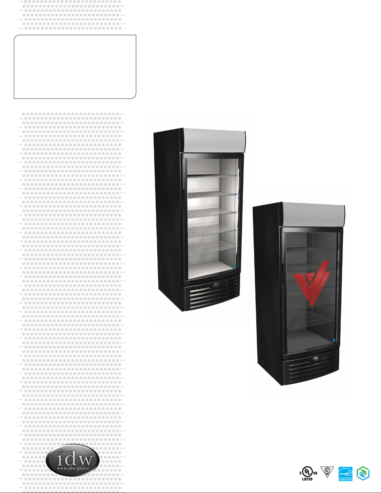
G-Series Cooler
Instruction Manual
G-26c/GCG-26c
NSF/ANSI7
SA44689
Innovative DisplayWorks, Inc. 3
G-26c/GCG-26c
G-Series Cooler
Instruction Manual
G-26c/GCG-26c
For Future Reference
• This easy-to-use manual will guide you in getting the best use of your cooler.
• Remember to record the model number and the serial number. This information can be
found on the inside of your cooler.
• Keep your receipt with this manual for future warranty service.
Model #:
Serial #:
Date of Purchase:
TABLE OF CONTENTS
Parts & Identication........................................................ 4
Safety Precautions............................................................ 5
Installation......................................................................... 6
Ambient Environment.................................................. 6
Preparation Prior to Operation.................................... 6
Electrical Requirements ............................................... 6
Flammable Refrigerant Warnings .................................. 7
Leveling............................................................................. 7
Shelving Installation......................................................... 7
Interior Light Replacement............................................. 8
Door LED Light Replacement......................................... 8
Canopy Light Replacement ............................................ 9
Canopy Graphic Replacement....................................... 9
Setting Up Power Cord Holder ....................................10
Startup, Operation & Temperature Adjustment.........10
Lit Door ‘Logo’ Switch ...................................................10
Controlling Motion Logo ..............................................10
Maintenance...................................................................11
Condenser...................................................................11
Cleaning.......................................................................11
Specications .................................................................12
Troubleshooting.............................................................13
G-26c Circuit & Electrical Wiring Diagrams.......... 14-16
GCG-26c Circuit & Electrical Wiring Diagrams.... 17-19
G-26c/GCG-26c (K)
Models:
G-26-C934B
G-26-CB934B
G-26-CP934B
G-26-CW934B
G-26-CZ934B
G-26-C934B-HC
G-26-CP934B-HC
G-26-CZ934B-HC
G-26-CB934B-HC
G-26-CW934B-HC
GCG-26-C934B
GCG-26-CB934B
GCG-26-C2934B
GCG-26-CP934B
GCG-26-CW934B
GCG-26-CW2934B
GCG-26-CZ934B
GCG-26-CZ2934B
GCG-26-CP2934B
GCG-26-C934B-HC
GCG-26-C2934B-HC
GCG-26-CP934B-HC
GCG-26-CP2934B-HC
GCG-26-CW2934B-HC
GCG-26-CB934B-HC
GCG-26-CW934B-HC
GCG-26-CZ934B-HC
GCG-26-CZ2934B-HC
GCG-26-CA934B
GCG-26-CA2934B
GCG-26-CA934B-HC
GCG-26-CA2934B-HC
G-26c/GCG-26c
Models:
G-26-C334B
G-26-CB334B
G-26-CP334B
G-26-CW334B
G-26-C334B-HC
G-26-CP334B-HC
GCG-26-C334B
GCG-26-CB334B
GCG-26-C2334B
GCG-26-CP334B
GCG-26-CW334B
GCG-26-CW2334B
GCG-26-CZ334B
GCG-26-CZ2334B
GCG-26-CA334B
GCG-26-C334B-HC
GCG-26-C2334B-HC
GCG-26-CP334B-HC
GCG-26-CA334B-HC
Innovative DisplayWorks, Inc.
Instruction Manual
4 5
G-26c/GCG-26c
Innovative DisplayWorks
offi ce 909.447.8254 • fax 909.305.8756 • toll free 877.307.2665 • www.idw.global
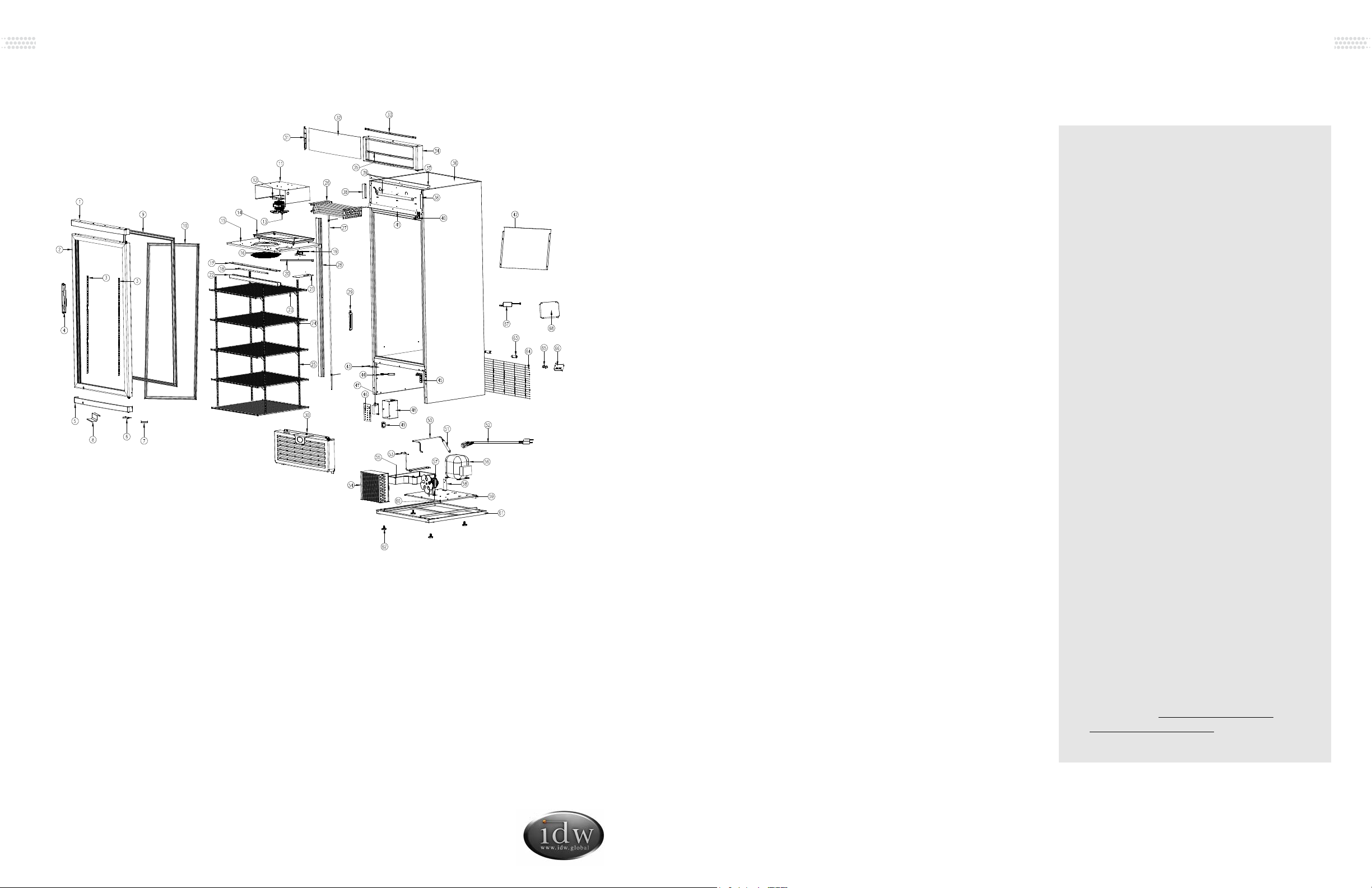
PARTS & IDENTIFICATION
Last Revised: September 25, 2019 12:17 PM
G-26c/GCG-26c
1. Top Plastic Strip of Glass Door
2. Glass Door
3. LED Light in the Glass Door
4. Door Handle
5. Low Plastic Strip of Glass Door
6. Door Limiter
7. Door Switch on Glass Door
8. Door Support
9. LED Light Cover (4)
10. Door Gasket
11. Side Panel
12. Fan Support
13. Evaporator Fan
14. Water Container
15. Control Panel
16. Fan Guard
17. Lamp Stand
18. LED Light
19. Thermostat
20. Sensor
21. Thermostat Panel
22. LED Light Cover
23. Shelf (6)
24. Shelf Clips (24)
25. Pilasters (4)
26. Evaporator
27. Return Pipe
28. Return Pipe Cover
29. Thermometer
30. Grill
31. Inserts
32. Light Canopy Cover
33. Top Strip Inside Light Canopy
34. Outline Border of Light Canopy
35. Low Strip Inside Light Canopy
36. Foam Cabinet
37. Top Frame of Light Canopy
38. Left and Right Support of Light
Canopy (2)
39. LED Light Inside Light Canopy
40. Top Hinge
41. Low Frame of Light Canopy
42. Plenum
43. Bracket for Grill
44. Magnetic Switch
45. Lower Hinge
46. Electric Box Cover
47. Transformer for LED Light
48. Electric Box
49. Electric Relay
50. Connecting Tube for Filter Dryer
51. Filter Dryer
52. Power Cord
53. Connecting Tube for Condenser
54. Condenser
55. Drain Pan
56. Compressor
57. Condenser Fan
58. Filter Dryer Bracket
59. Upper Baseboard
60. Fan Support
61. Lower Baseboard
62. Leveling Legs (4)
63. Bumper Block (2)
64. Compressor Guard
65. Light Switch (2)
66. Bracket for Light Switch
67. LED Controller
68. Power Supply Cover
G-26c/GCG-26c 1. When using this appliance, always follow
the basic safety precautions:
2. Read the entire User’s Manual before
operating this appliance.
3. Use this appliance only for its intended
purpose as described in this User’s Manual.
4. This appliance must be properly installed
in accordance with the installation
instructions before being used.
5. IDW requires that a dedicated circuit be
used for the unit. Failure to do so voids
warranty.
6. Never unplug your cooler by pulling on the
power cord. Always grasp the plug rmly
and pull it straight out from the outlet.
7. Unplug your appliance before cleaning or
making any repairs. Note: If for any reason
this product requires service, we strongly
recommend that a certifi ed technician
perform the service.
8. When disconnecting the power source,
wait at least 5 minutes to reconnect the
power to avoid damage to the compressor
and the cooling system.
9. Immediately repair or replace all electrical
cords that have become frayed or other-
wise damaged. Do not use a cord that
shows cracks or abrasion damage along its
length, the plug or the connector end.
10. Do not operate or store your appliance
near or around explosive fumes, gasoline
or other fl ammable vapors and liquids.
11. Do not use fl ammable liquids to clean unit.
12. Setting the temperature control to the
0 position does not remove power to
the light circuit, perimeter heaters, or
evaporator fans.
13. Do not adjust the temperature control.
The temperature control is factory set for
maximum performance.
SAFETY INSTRUCTIONS
PLEASE SAVE THESE
INSTRUCTIONS!
DANGER!
PROPER DISPOSAL OF THE
REFRIGERATOR
Pre-Caution, Non-Operating Coolers
Should Have:
1. Door removed.
2. Shelves kept in place in order
to prevent any small child from
climbing inside cooler.
For Proper Disposal of Cooler:
Distributors/retailers need to contact
a quali ed service technician:
1. To recover all refrigerant from
the cooler
2. To remove the compressor
or remove the oil from the
compressor
Then the distributor/retailer can
contact their local metal recycling
center to pick up the remaining
cabinet, shelves, etc. By law, disposal
of hazardous wastes may be subject
to nes and imprisonment under
the provisions of the environmental
regulations. For more information
please visit: http://www.epa.gov/
osw/hazard/index.htm
Innovative DisplayWorks, Inc.
Instruction Manual
6 7
G-26c/GCG-26c
INSTALLATION
Installation of the cooler must be done according to applicable local codes or equivalent.
Ambient Environment
• Place cooler on an even surface to reduce
vibration and noise.
• To transport, do not tilt the cooler beyond
a 45 degree angle.
• Do not place cooler in direct sunlight or
near any heat sources.
• Do not place cooler in environment
temperatures that exceed 80°F.
• Do not place cooler in below normal
temperatures.
• Do not place cooler in extreme humid
environments, this may cause components
to rust.
• Do not place cooler near constant running
or splattering water, this may cause
immediate damage to refrigeration system.
• Must allow at least 4” between rear of
cooler and wall for proper ventilation and
heat dissipation of cooler.
• Do not place furniture or other articles with
sharp edges near the cooler in order to
prevent damage to the glass door.
• This cooler is for indoor use.
• Place unit in it’s nal location, making certain
there is adequate ventilation in the room.
WARNING: Warranty is void if ventilation
is insuf cient.
Preparation Prior to Operation
Electrical Requirements
• Remove all packaging materials before
using cooler. This includes: foam pedestal,
adhesive tape (used to x accessories) and
protective gaskets.
• Inspect cooler for concealed damage.
Immediately le a claim with the freight
carrier if there is damage. IDW is not
responsible for damage incurred during
shipping.
• Cooler must remain unplugged in an
upright position for 1 hour prior to use.
• Clean the interior surface with a soft cloth
and lukewarm water before operation.
• Ensure that drain hose or hoses are
positioned in the pan.
• Remove plug and cord from inside the
lower rear of the cooler.
• The unit should be placed close enough
to the electrical supply so that extension
cords are not used.
• This model operates with a 110-120V/60Hz
power supply. Check the electrical outlet
for proper voltage.
• Dedicate one outlet for the use of the
cooler.
• Do not use an extension cord or any other
multiple connectors as this can lead to
compressor failure.
• If the cord is damaged, it must be replaced.
• For your safety, plug the unit into a
grounded wall outlet. Please check with a
certi ed electrician for details.
WARNING: Do not use extension cords.
WARNING: Compressor warranties are
void if compressor burns out due to low
voltage.
WARNING: Power cord ground pin must
NOT be removed!
LEVELING
• Set unit in its nal location making certain there is adequate
ventilation in the room.
WARNING: Warranty is void if ventilation is insuf cient.
• Proper leveling of the cooler is critical to it operating
correctly. Condensation removal and door operation are
both affected by leveling.
• The cooler should be leveled front to back and side to side
with a level.
• Ensure the drain hose or hoses are positioned in the pan.
• Remove the plug and cord from inside the lower rear of the
cooler.
• The unit should be placed close enough to the electrical
supply so that extension cords are never used.
CAUTION FLAMMABLE REFRIGERANT
• DANGER – Risk Of Fire Or Explosion. Flammable Refrigerant Used. To Be Repaired
Only By Trained Service Personnel. Do Not Puncture Refrigerant Tubing.
• CAUTION – Risk Of Fire Or Explosion. Flammable Refrigerant Used. Consult Repair
Manual/Owner’s Guide Before Attempting To Install or Service This Product. All Safety
Precautions Must be Followed.
• CAUTION – Risk Of Fire Or Explosion. Dispose Of Properly In Accordance With
Federal Or Local Regulations. Flammable Refrigerant Used.
• CAUTION – Risk Of Fire Or Explosion Due To Puncture Of Refrigerant Tubing; Follow
Handling Instructions Carefully. Flammable Refrigerant Used.
• CAREFUL - Handling, moving and operating of the refrigerator or freezer to avoid
either damaging the refrigerant tubing, or increasing the risk of a leak.
• CAUTION - Component parts shall be replaced with like components and that
servicing shall be done by factory authorized service personnel, so as to minimize the
risk of possible ignition due to incorrect parts or improper service.
DANGER – Risk Of Fire Or Explosion. Flammable Refrigerant Used. To Be
Repaired By Trained Service Personnel Only. Do Not Puncture Refrigerant Tubing.
CAUTION – Risk Of Fire Or Explosion. Flammable Refrigerant Used. Consult
Repair Manual/Owner’s Guide Before Attempting To Service This Product. All
Safety Precautions Must be Followed.
CAUTION – Risk Of Fire Or Explosion. Dispose Of Property In Accordance With
Federal Or Local Regulations. Flammable Refrigerant Used.
CAUTION – Risk Of Fire Or Explosion Due To Puncture Of Refrigerant Tubing;
Follow Handling Instructions Carefully. Flammable Refrigerant Used.
CAUTION FLAMMABLE - R600a Refrigerant
DANGER - Risque d'incendie ou d'explosion. Réfrigérant inflammable utilisé.
Pour être réparé que par un personnel de maintenance qualifié. Ne pas percer
réfrigérant Tubing.
ATTENTION - Risque d'incendie ou d'explosion. Réfrigérant inflammable utilisé.
Consultez manuel / guide de l 'utilisateur de réparation avant de tenter de
réparer ce produit. Toutes les précautions de sécurité doivent être respectées.
ATTENTION - Risque d'incendie ou d'explosion. Aliéner des biens conformé-
ment à la réglementation fédérales ou locales. Réfrigérant inflammable utilisé.
ATTENTION - Risque d'incendie ou une explosion due à la perforation de
tuyaux de réfrigérant; suivre les instructions de manipulation avec précaution.
Réfrigérant inflammable utilisé.
PRUDENCE INFLAMMABLE - R600a Réfrigérant
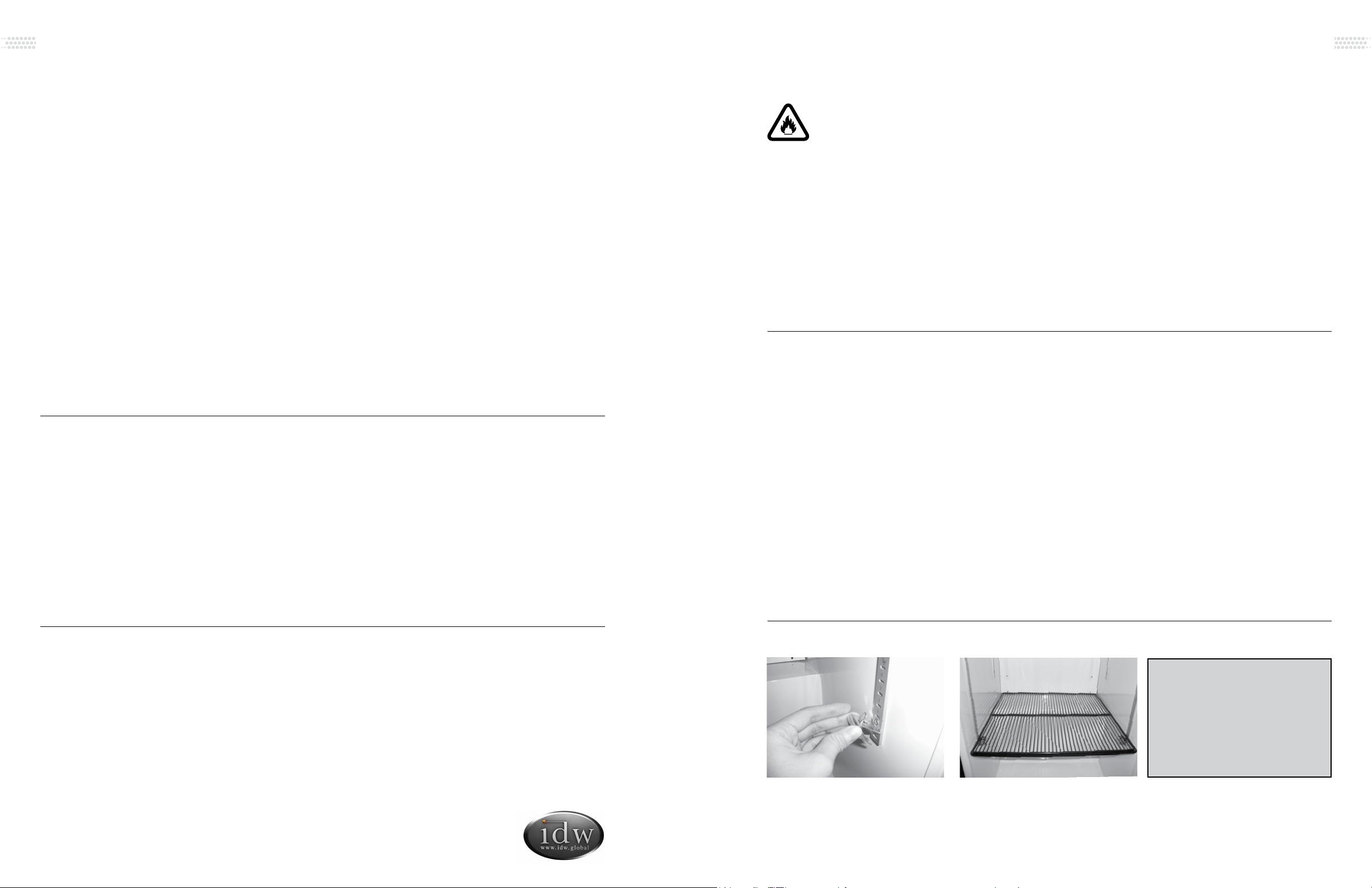
SHELVING INSTALLATION
(Maximum load per shelf is lbs/ kg)
Display refrigerators can be loaded within the shelf dimensions from the front
to back side. They can also be loaded in any space from the bottom to the top
interior cabinet. Do not allow product to block the evaporator fan cover because
the evaporator fan helps the cooler to ventilate properly.
Display refrigerators can be loaded within the shelf dimensions from the front
to back side. They can also be loaded in any space from the bottom to the top
interior cabinet. Do not allow product to block the evaporator fan cover because
the evaporator fan helps the cooler to ventilate properly.
Display refrigerators can be loaded within the shelf dimensions from the front
to back side. They can also be loaded in any space from the bottom to the top
interior cabinet. Do not allow product to block the evaporator fan cover because
the evaporator fan helps the cooler to ventilate properly.
Display refrigerators can be loaded within the shelf dimensions from the front
to back side. They can also be loaded in any space from the bottom to the top
interior cabinet. Do not allow product to block the evaporator fan cover because
the evaporator fan helps the cooler to ventilate properly.
Display refrigerators can be loaded within the shelf dimensions from the front
to back side. They can also be loaded in any space from the bottom to the top
interior cabinet. Do not allow product to block the evaporator fan cover because
the evaporator fan helps the cooler to ventilate properly.
Shelf clips should be level so
shelf lays fl at
Securely insert shelf clips into
pilasters
[Model(s)] maximum load per shelf is lbs/ kg
[Model(s)] maximum load per shelf is lbs/ kg
[Model(s)] maximum load per shelf is lbs/ kg
[Model(s)] maximum load per shelf is lbs/ kg
[Model(s)] maximum load per shelf is lbs/ kg
[Model(s)] maximum load per shelf is lbs/ kg
[Model(s)] maximum load per shelf is lbs/ kg
[Model(s)] maximum load per shelf is lbs/ kg
[Model(s)] maximum load per shelf is lbs/ kg
[Model(s)] maximum load per shelf is lbs/ kg
[Model(s)] maximum load per shelf is lbs/ kg
[Model(s)] maximum load per shelf is lbs/ kg
[Model(s)] maximum load per shelf is lbs/ kg
[Model(s)] maximum load per shelf is lbs/ kg
(Maximum load per shelf is 123 lbs)
Display refrigerators can be loaded with-
in the shelf dimensions from the front
to back side. They can also be loaded
in any space from the bottom to the top
interior cabinet. Do not allow product to
block the evaporator fan cover because
the evaporator fan helps the cooler to
ventilate properly.

Innovative DisplayWorks, Inc.
Instruction Manual
8 9
G-26c/GCG-26c
INTERIOR LIGHT REPLACEMENT
Instructions are as follows:
DOOR LED LIGHT REPLACEMENT
1Unplug Cooler
1Press two sides of plastic
cover by the ngers and
remove it.
2Remove plastic cover.
2Disconnect the lights.
3Disconnect top light strand.
3Unscrew all screws using a
Phillip’s screwdriver.
4Disconnect middle light
strand.
4Remove LED light strand.
5Unscrew light strand.
5To install LED lights follow the above directions in reverse
order.
6Remove entire light strand.
7To install LED lights follow the
above directions in reverse order.
NOTE: If there are any
malfunctions with the main
control panel of LED lights,
please contact a professional
for replacement.
CANOPY LIGHT REPLACEMENT
Instructions are as follows:
CANOPY GRAPHIC REPLACEMENT
Instructions are as follows:
1Unscrew the graphic holder
on the left hand side of the
canopy.
1Unscrew the graphic holder
on the left hand side of the
canopy.
2Carefully slide out the entire
graphic.
3Replace with new graphic.
4Secure the graphic holder
by fastening the screw.
2Carefully slide out the entire
graphic.
3Disconnect the light.
4Hold the LED light, tilt
slightly, and then remove it
from the bracket..
5To Install LED lights follow
the above directions in
reverse order.
Innovative DisplayWorks, Inc.
Instruction Manual
10 11
G-26c/GCG-26c
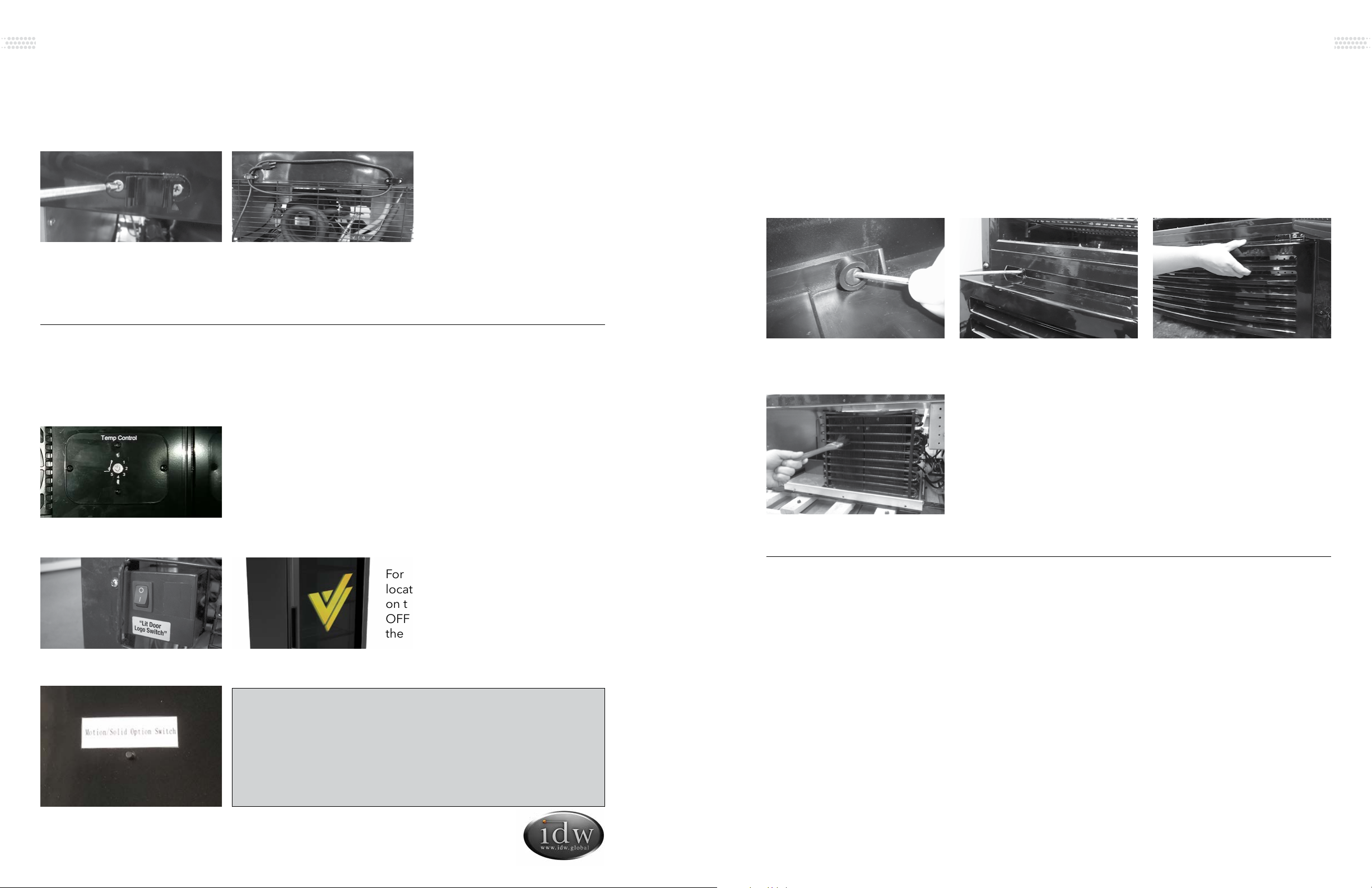
SETTING UP SPACERS & POWER CORD HOLDERS
These coolers are supplied with one set (2 pieces) of Spacers to hold the extra length of Power Cord.
START-UP, OPERATION AND TEMPERATURE ADJUSTMENT
Operation
Prior to stocking cooler with product, it should be operated empty for half an hour.
Temperature Adjustment
Switch Operation for Lit Door Logo
Button for Changing Motion Logo Modes
1Take out the two Spacers
and Screws supplied in the
Accessory Pack shipped with
the Cooler.
Performance tested position of
the thermostat is between 4-6.
For GCG coolers only. The light switch
located at the bottom left hand side,
on the rear of the cabinet, is the ON/
OFF switch for the Lit logo located on
the door of cooler.
2Use a Phillips screwdriver to
secure the two Spacers onto
the rear of the cooler.
Mode 1: The logo lights are permanently lit and do not
sequence.
Mode 2: The logo lights sequence showing the bottle
emptying and fl ashing full. This is the default setting.
Please Note: When replacing the controller, remove four (4)
screws on the rear cover plate to gain access.
MAINTENANCE
Condenser
It is essential to keep the condenser coils clean and free of dust and debris at all times. It is required
to periodically clean the condenser coils with a soft bristle brush or vacuum-cleaner to properly
maintain the refrigeration system. Failure to clean the condenser at regular intervals may cause
failure of the refrigeration system and could void the warranty.
Cleaning
• Unplug the cooler before cleaning.
• Use a soft cloth or sponge with soap and water (non-corrosive mild detergent), while cleaning.
After cleaning, wipe the cooler using a dry cloth to prevent the cooler from rusting.
• Do not spray water on the cooler, and do not use hard or steel brushes to clean the cooler.
• Do not use organic solvents, boiling water, scrubbing powders or acids while cleaning.
• A drain or waste outlet may be provided for draining of a display refrigerator. If a display
refrigerator drain is provided for fl ushing, it will have a minimum internal diameter of 1” (25mm)
If the cooler will be in a non-operational state for a long period of time, clean as instructed above,
and keep the door open until interior is dry.
2Using a small Phillips head
screwdriver and remove the
screws as shown.
1Remove the rubber cap
from the front grill.
3The front grill can now be
removed by pulling it up.
4Using plastic bristle brush,
carefully clean the condenser
being aware that coils can
bend or be damaged if too
much force is used.
5Replace grill and use the
Phillips screwdriver to
tighten the screws into
place, replace the rubber
caps.
Innovative DisplayWorks, Inc.
Instruction Manual
12 13
G-26c/GCG-26c
• Serial number from the interior wall of the
cooler
• Coolers’ installation address and contact
information
• Installation location hours and operation
• Nature of problem
• Any reports of power interruptions
• Recent service or maintenance completed
on the cooler
• Has the cooler been relocated from original
installation location
• Clear access to the cooler
• Coolers’ instruction manual
Information to provide to your qualifi ed service professional:
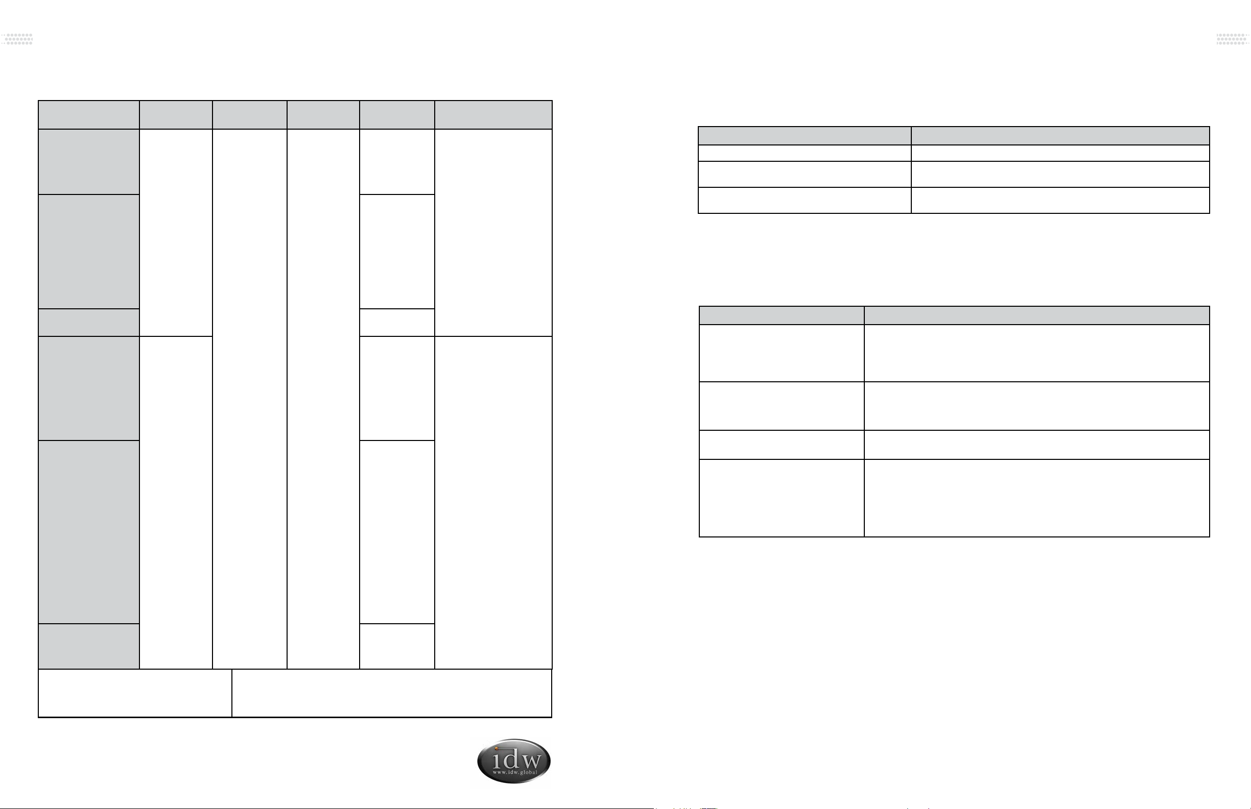
Situation Causes
Liquid fl owing noise within cooler • This is the sound of the cooling agent fl owing through the pipes.
Refrigeration system is shutdown for longer periods
of time while temperature inside is still very low
• This refrigerator is well insulated and can maintain a relatively
ambient temperature.
Condensation on door/lid • This may be due to a high indoor humidity or the cooler’s
temperature is set too low. Wipe the door dry with a towel.
Issues Solutions
Cooler is not working properly Please check power supply:
• Check the electrical outlet for power, and that the plug is properly inserted.
• Check to see if the circuit breaker is tripped or the fuse is blown.
• Check if the condenser is free of dirt and debris.
• Check for low voltage
Cooler is not keeping product cool • Provide ample space between all products to ensure proper circulation of air.
• Keep unit away from direct sunlight or other heating source.
• Keep the door closed as often as possible.
• Be certain the cooler is not touching external objects or walls.
Excessive noise • Be certain the cooler is placed on a level surface.
• Be certain the cooler is not touching external objects or walls.
Compressor turns on and off frequently • The room temperature is higher than normal.
• The door is not closed completely.
• The door gasket is not sealed properly.
• There is insuf cient clearance around the cooler.
• The thermostat is not set properly.
• The frequency of cycling will be reduced when all of the product reaches the
set temperature.
TROUBLESHOOTING
The following are NOT malfunctions:
1This refrigerator has been designed and manufactured according to National standards. If there
are any questions during use, refer to this operation manual to help troubleshoot problems.
2When disposing of the cooler, please remove the door/lid and lock assembly to avoid children
accidentally becoming trapped inside the cooler.
Prior to calling service, check the following:
AFTER SALES SERVICE
Any product has the possibility of malfunction. Please observe the cooler’s operation and any
changes to product being stored. If there are any abnormal cases, refer to the table below. If there
is still no change after following the below instructions, please inform our service center in a timely
manner to avoid a further loss of the unit.
MODEL VOLUME(L)
RATED
VOLTAGE
RATED
CURRENT
LAMP INPUT
POWER REFRIGERANT
G-26-C334B
G-26-CB334B
G-26-CP334B
G-26-CW334B
G-26-C334B-HC
G-26-CP334B-HC
22.6ft3
110-120V/60Hz 2.7A
13 W
R290/140g
GCG-26-C334B
GCG-26-CB334B
GCG-26-C2334B
GCG-26-CP334B
GCG-26-CW334B
GCG-26-CW2334B
GCG-26-CZ334B
GCG-26-CZ2334B
GCG-26-C334B-HC
GCG-26-C2334B-HC
GCG-26-CP334B-HC
20 W
GCG-26-CA334B
GCG-26-CA334B-HC 23 W
G-26-C934B
G-26-CB934B
G-26-CP934B
G-26-CW934B
G-26-CZ934B
G-26-C934B-HC
G-26-CP934B-HC
G-26-CZ934B-HC
G-26-CB934B-HC
G-26-CW934B-HC
22.3ft3
13 W
R290/83g
GCG-26-C934B
GCG-26-CB934B
GCG-26-C2934B
GCG-26-CP934B
GCG-26-CW934B
GCG-26-CW2934B
GCG-26-CZ934B
GCG-26-CZ2934B
GCG-26-CP2934B
GCG-26-C934B-HC
GCG-26-C2934B-HC
GCG-26-CP934B-HC
GCG-26-CP2934B-HC
GCG-26-CW2934B-HC
GCG-26-CB934B-HC
GCG-26-CW934B-HC
GCG-26-CZ934B-HC
GCG-26-CZ2934B-HC
20 W
GCG-26-CA934B
GCG-26-CA2934B
GCG-26-CA934B-HC
GCG-26-CA2934B-HC
23 W
NSF/ASNI-7: Type II Display Refrigerator A display refrigerator intended for use in an area where the
environmental conditions are controlled and maintained so that the
ambient temperature does not exceed 80°F (27°C).
SPECIFICATIONS
Innovative DisplayWorks, Inc.
Instruction Manual
14 15
G-26c/GCG-26c
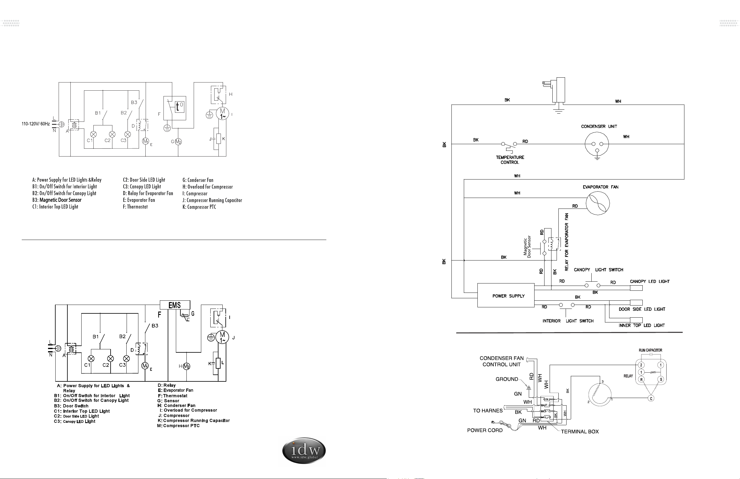
CIRCUIT DIAGRAM (G-26C)
FOR MODELS: G-26-C334B, G-26-CB334B, G-26-CP334B, G-26-CW334B, G-26-C334B-HC, G-26-CP334B-HC
CIRCUIT DIAGRAM (G-26C (K))
FOR MODELS: G-26-CB934B, G-26-CP934B, G-26-CW934B, G-26-CZ934B, G-26-C934B-HC, G-26-CP934B-HC,
G-26-CZ934B-HC, G-26-CB934B-HC, G-26-CW934B-HC
ELECTRICAL WIRING DIAGRAM (G-26C)
FOR MODELS: G-26-C334B, G-26-CB334B, G-26-CP334B, G-26-CW334B, G-26-C334B-HC, G-26-CP334B-HC

Innovative DisplayWorks, Inc.
Instruction Manual
16 17
G-26c/GCG-26c
EMS
L
Sensor
L
CIRCUIT DIAGRAM (GCG-26C (K))
FOR MODELS: GCG-26-CB934B , GCG-26-C2934B, GCG-26-CP934B, GCG-26-CW934B, GCG-26-CW2934B,
GCG-26-CZ934B, GCG-26-CZ2934B, GCG-26-CA934B, GCG-26-CP2934B, GCG-26-CA2934B, GCG-26-C934B-HC,
GCG-26-C2934B-HC, GCG-26-CP934B-HC, GCG-26-CA934B-HC, GCG-26-CP2934B-HC, GCG-26-CA2934B-HC,
GCG-26-CW2934B-HC, GCG-26-CZ934B-HC, GCG-26-CZ2934B-HC
CIRCUIT DIAGRAM (GCG-26C)
FOR MODELS: GCG-26-C334B, GCG-26-CB334B , GCG-26-C2334B, GCG-26-CP334B, GCG-26-CW334B,
GCG-26-CW2334B, GCG-26-CZ334B, GCG-26-CZ2334B, GCG-26-CA334B, GCG-26-C334B-HC, GCG-26-C2334B-HC,
GCG-26-CP334B-HC, GCG-26-CA334B-HC
ELECTRICAL WIRING DIAGRAM (G-26C (K))
FOR MODELS: G-26-CB934B, G-26-CP934B, G-26-CW934B, G-26-CZ934B, G-26-C934B-HC, G-26-CP934B-HC,
G-26-CZ934B-HC, G-26-CB934B-HC, G-26-CW934B-HC

Innovative DisplayWorks, Inc.
Instruction Manual
18 19
G-26c/GCG-26c
ELECTRICAL WIRING DIAGRAM (GCG-26C (K))
FOR MODELS: GCG-26-C934B, GCG-26-CB934B , GCG-26-C2934B, GCG-26-CP934B, GCG-26-CW934B,
GCG-26-CW2934B, GCG-26-CZ934B, GCG-26-CZ2934B, GCG-26-CA934B, GCG-26-CP2934B, GCG-26-CA2934B,
GCG-26-C934B-HC, GCG-26-C2934B-HC, GCG-26-CP934B-HC, GCG-26-CA934B-HC, GCG-26-CP2934B-HC,
GCG-26-CA2934B-HC, GCG-26-CB934B-HC, GCG-26-CW934-HC, GCG-26-CW2934B-HC, GCG-26-CZ934B-HC,
GCG-26-CZ2934B-HC
ELECTRICAL WIRING DIAGRAM (GCG-26C)
FOR MODELS: GCG-26-C334B, GCG-26-CB334B , GCG-26-C2334B, GCG-26-CP334B,
GCG-26-CW334B, GCG-26-CW2334B, GCG-26-CZ334B, GCG-26-CZ2334B, GCG-26-CA334B, GCG-26-C334B-HC,
GCG-26-C2334B-HC, GCG-26-CP334B-HC, GCG-26-CA334B-HC

Innovative DisplayWorks, Inc.
To locate the distributor in your area go to: http://www.idw.global/contact/#distributors
Other manuals for G-Series
12
This manual suits for next models
48
Table of contents
Other IDW Freezer manuals


