IDW G-10F User manual

G-Series Cooler
Instruction Manual
G-10f/GCG-10f
UPRIGHT COOLER
Manual is for the following models:
G-10F, G-10-F33EB
GCG-10F, GCG-10-F33EB
GCG-10F2, GCG-10-F233EB
G-10-F33EB-HC, GCG-10-F33EB-HC
GCG-10-F233EB-HC

Manual is for the following models:
G-10F
G-10-F33EB
GCG-10F
GCG-10-F33EB
GCG-10F2
GCG-10-F233EB
G-10-F33EB-HC
GCG-10-F33EB-HC
GCG-10-F233EB-HC
G-10f
GCG-10f
Instruction Manual
Innovative DisplayWorks
G-10f/GCG-10f
2
FOR YOUR FUTURE REFERENCE
• This easy-to-use manual will guide you in getting the best use of your cooler.
• Remember to record the model number and the serial number. This information can be found on the
inside of your cooler.
• Keep your receipt with this manual for future warranty service.
Model #:
Serial #:
Date of Purchase:
TABLE OF CONTENTS
Parts & Identication ..........................................................3
Safety Precautions ..............................................................4
Features..............................................................................5
Instructions.........................................................................5
Flammable R290 Warnings .................................................5
Ambient Environment..........................................................5
Preparation Before Operation..............................................6
Replacing the Interior Light.................................................7
Replacing the Door LED Lights.............................................8
Setting Up Power Cord Holder..............................................8
Startup, Operation & Temperature Adjustment.....................9
Lit Door ‘Logo’ Switch..........................................................9
Repair & Maintenance for Refrigeration Drawer...................9
Condenser Maintenance ....................................................10
Maintenance.....................................................................10
Cleaning Shutdown Questions & Answers...........................10
Reversible Door Exchange ................................................. 11
Replacing the Fuse ............................................................ 13
Troubleshooting ................................................................ 14
After-Sales Service............................................................. 14
G-10f Circuit Diagram........................................................ 15
G-10f Electrical Wiring Diagram......................................... 16
GCG-10f Circuit Diagram.................................................... 17
GCG-10f Electrical Wiring Diagram..................................... 18

Instruction Manual
3

Innovative DisplayWorks
G-10f/GCG-10f
4
SAFETY PRECAUTIONS
When using this appliance, always follow the basic safety precautions:
1. Read the entire User’s Manual before operating this appliance.
2. Use this appliance only for its intended purpose as described in this User’s Manual.
3. This cooler must be properly installed in accordance with the installation instructions before being used. See grounding
instructions on page 6.
4. Never unplug your cooler by pulling on the power cord. Always grasp the plug rmly and pull it straight out from the
outlet.
5. Unplug your cooler before cleaning or making any repairs. (Note: If for any reason this product requires service, we
strongly recommend that a certi ed technician perform the service.)
6. Immediately repair or replace all electrical cords that have become frayed or otherwise damaged. Do not use a cord that
shows cracks or abrasion damage along its length, the plug or the connector end.
7. This cooler should not be recessed or built into an enclosed cabinet. It is designed for freestanding installation only.
8. Do not operate or store your cooler near or around explosive fumes, gasoline or other fl ammable vapors and liquids.
9. Setting the temperature control to the 0 position does not remove power to the light circuit, perimeter heaters, or
evaporator fans.
Please save these instructions!
DANGER!
Proper Disposal of the Refrigerator
To prevent any risk of child entrapment when discarding your cooler remove the doors and leave the shelves in place so that
children cannot easily climb inside.
PRE-CAUTION, NON-OPERATING COOLERS SHOULD HAVE:
1. Glass door removed.
2. Shelves kept in place in order to prevent any small child from climbing inside cooler.
FOR PROPER DISPOSAL OF COOLER: Distributors / retailers need to contact a quali ed service technician:
1. To recover all Freon/refrigerant from the cooler
2. To remove the compressor or remove the oil from the compressor
Then the distributor/ retailer can contact their local metal recycling center to pick up the remaining cabinet, shelves, etc. By law,
disposal of hazardous wastes may be subject to nes and imprisonment under the provisions of the environmental regulations.
For more information please visit: http://www.epa.gov/osw/hazard/index.htm

Instruction Manual
5
Shelving Installation
• Securely insert shelf clips into pilasters
• Shelf clips should be level so shelf lays fl at
• Place shelf on shelf clips
FEATURES
•Designed with an elegant shape and quick refrigeration speed, this commercial-grade product is an ideal choice for
shopping malls, supermarkets, hotels, etc.
•Transparent glass doors are built with hollow, toughened glass that provides a high level of heat insulation. Clear
doors allow for high product visibility.
•The forced air system allows for fast cooling speeds, which helps maintain a consistent temperature.
•Adjustable shelves allow for a wide variety of products to be stocked.
•A built-in lock offers the ability to secure products.
•The refrigeration unit is designed for easy access, allowing for fast and simple repairs.
•This equipment is intended for storage and display of non-hazardous packaged product.
CAUTION FLAMMABLE REFRIGERANT
• DANGER – Risk Of Fire Or Explosion. Flammable Refrigerant Used. To Be Repaired Only By Trained Service
Personnel. Do Not Puncture Refrigerant Tubing.
• CAUTION – Risk Of Fire Or Explosion. Flammable Refrigerant Used. Consult Repair Manual/Owner’s Guide
Before Attempting To Install or Service This Product. All Safety Precautions Must be Followed.
• CAUTION – Risk Of Fire Or Explosion. Dispose Of Properly In Accordance With Federal Or Local Regulations.
Flammable Refrigerant Used.
• CAUTION – Risk Of Fire Or Explosion Due To Puncture Of Refrigerant Tubing; Follow Handling Instructions
Carefully. Flammable Refrigerant Used.
INSTRUCTIONS
Ambient Environment
•Place cooler on an even surface to reduce vibration and noise.
•To transport, do not tilt the cooler beyond a 45 degree angle.
•Do not place cooler in direct sunlight or near any heat sources.
•Do not place cooler in environment temperatures that exceed 109°F.
•Do not place cooler in below normal temperatures.
•Do not place cooler in extreme humid environments, this may cause components to rust.
•Do not place cooler near constant running or splattering water, this may cause immediate damage to refrigeration
system.
•Must allow at least 4” between rear of cooler and wall for proper ventilation and heat dissipation of cooler.
•Do not place furniture or other articles with sharp edges near the cooler in order to prevent damage to the glass door.
DANGER – Risk Of Fire Or Explosion. Flammable Refrigerant Used. To Be
Repaired By Trained Service Personnel Only. Do Not Puncture Refrigerant Tubing.
CAUTION – Risk Of Fire Or Explosion. Flammable Refrigerant Used. Consult
Repair Manual/Owner’s Guide Before Attempting To Service This Product. All
Safety Precautions Must be Followed.
CAUTION – Risk Of Fire Or Explosion. Dispose Of Property In Accordance With
Federal Or Local Regulations. Flammable Refrigerant Used.
CAUTION – Risk Of Fire Or Explosion Due To Puncture Of Refrigerant Tubing;
Follow Handling Instructions Carefully. Flammable Refrigerant Used.
CAUTION FLAMMABLE - R600a Refrigerant
DANGER - Risque d'incendie ou d'explosion. Réfrigérant inflammable utilisé.
Pour être réparé que par un personnel de maintenance qualifié. Ne pas percer
réfrigérant Tubing.
ATTENTION - Risque d'incendie ou d'explosion. Réfrigérant inflammable utilisé.
Consultez manuel / guide de l 'utilisateur de réparation avant de tenter de
réparer ce produit. Toutes les précautions de sécurité doivent être respectées.
ATTENTION - Risque d'incendie ou d'explosion. Aliéner des biens conformé-
ment à la réglementation fédérales ou locales. Réfrigérant inflammable utilisé.
ATTENTION - Risque d'incendie ou une explosion due à la perforation de
tuyaux de réfrigérant; suivre les instructions de manipulation avec précaution.
Réfrigérant inflammable utilisé.
PRUDENCE INFLAMMABLE - R600a Réfrigérant
80°F

Innovative DisplayWorks
G-10f/GCG-10f
6
PREPARATION PRIOR TO OPERATION
•Remove all packaging materials before using cooler.
Thisincludes:foampedestal,adhesivetape(usedtoxaccessories)andprotectivegaskets.
• Inspectcoolerforconcealeddamage.Immediatelyleaclaimwiththefreightcarrierifthereisdamage.
IDW is not responsible for damage incurred during shipping.
•For proper operation, place the cooler on a dry, level surface.
• Cleantheinteriorsurfacewithasoftclothandlukewarmwaterbeforeoperation.
•Keep cooler in an upright position for 30 minutes prior to use.
• IDWrequiresthatasoleusecircuitbededicatedfortheunit.Failuretodosovoidswarranty.
WARNING:Donotuseextensioncords.
WARNING:Compressorwarrantiesarevoidifcompressorburnsoutduetolowvoltage.
WARNING:Powersupplycordshouldnotberemovedoralteredinanyway.
Leveling
•Setunitinitsnallocation,makingcertainthereisadequateventilationintheroom.
WARNING:Warrantyisvoidifventilationisinsufcient.
•Proper leveling of the G-10f/GCG-10f cooler is critical to it operating correctly. Condensation removal and
dooroperationwillbeaffectedbyleveling.
<The cooler should be leveled front to back and side to side with a level.
•Ensure that drain hose or hoses are positioned in the pan.
•Removeplugandcordfrominsidethelowerrearofthecooler.
•Theunitshouldbeplacedcloseenoughtotheelectricalsupplysothatextensioncordsareneverused.
Shelving Installation
• Securely insert shelf clips into pilasters
• Shelf clips should be level so shelf lays fl at
• Place shelf on shelf clips
(Maximum load per shelf is 30kg )
Display refrigerators can be loaded within the shelf dimensions from the front to back side.
They can also be loaded in any space from the bottom to the top interior cabinet.
Do not allow product to block the evaporator fan cover because the evaporator fan
helps the cooler to ventilate properly.

Instruction Manual
REPLACING THE INTERIOR LIGHT
1 Presstwosidesofplasticcoverbythengersandremoveit.
5 ToinstallLEDlightsfollowtheabovedirectionsinreverseorder.
2Disconnect the lights.
4Remove LED light strand.
3 Unscrew(3)screwsusingaPhillip’sscrewdriver.
7

Innovative DisplayWorks
G-10f/GCG-10f
REPLACING THE DOOR LED LIGHTS
1Unplug the cooler.
2Remove
plastic
cover.
3Disconnect top
light strand.
4Disconnect
middle light
strand.
5 Unscrewlightstrand.
8
6Remove entire light strand.
7 ToinstallLEDlightsfollowtheaboveinstructionsinreverseorder.
Notes:IfthereareanymalfunctionswiththemaincontrolpanelofLEDlights,
please contact a professional for replacement.
SETTING UP SPACER & POWER CORD HOLDERS
TheG-10f/GCG-10fissuppliedwithoneset(2pieces)ofSpacerstoholdthe
extralengthofPowerCord
1TakeoutthetwoSpacersandscrewssuppliedintheAccessoryPackshippedwith
the Cooler.
2UseaPhillipsscrewdrivertosecurethetwoSpacersontothe
rear of the cooler.

Instruction Manual
STARTUP, OPERATION AND TEMPERATURE ADJUSTMENT
Operation
•Priortostockingcoolerwithproduct,itshould
be operated empty for half an hour.
Temperature Adjustment
REPAIR AND MAINTENANCE FOR REFRIGERATION DRAWER
* A CERTIFIED TECHNICIAN IS REQUIRED TO REPAIR ALL
REFRIGERATION COMPONENTS FOR WARRANTY PURPOSES.
For convenient repair, the refrigeration components (compressor,
evaporator,condenser,evaporationfan,condensationfanandlter)are
designed using a split system; any component can be easily replaced.
Replacementprocedureisasfollows:
1Unplug the unit.
2 Removethescrewsfromthefrontgrill,andthenremovethegrill.
3Unplug all connections and terminals that are in need of repair.
9
•G-10f/GCG-10f performance testing
position of the thermostat is around 4-6.
•Componentshownattheleft
functionsasasecondarypower
sourceforlowvoltageitemssuchas
signs.
4 Usingascrewdriver,removethe(3)screws
fromtherefrigerationdrawerbaseplate.
5 SlidetheRefrigerationDrawerouttoeasilyaccess
refrigeration components. Remove the component to replace or
repair.
6 Afterrepair,re-installallpartsusingthereverseprocedure.
Lit Door “Logo”
Switch
Operation
• For GCG-10f
coolers only.
Thelightswitch
located at the bottom
left hand side on the rear of the
cabinetistheON/OFFswitchforthe
Lit logo located on the door of cooler.

Innovative DisplayWorks
G-10f/GCG-10f
CONDENSER MAINTENANCE
It is essential to keep the condenser coils clean and free of dust and debris at all
times.Itisrequiredtoperiodicallycleanthecondensercoilswithasoftbristlebrush
or vacuum-cleaner to properly maintain the refrigeration system. Failure to clean
the condenser at regular intervals may cause failure of the refrigeration system and
couldvoidthewarranty.
1 Remove the rubber cap from the front grill.
2UsingaPhillipsscrewdriver,removethethreescrewsas
shown.
3Thefrontplasticgrillcannowberemovedbypullingitup.
4Usingplasticbristlebrush,carefullycleanthecoilbeingawarethatnscanbendorbe
damagediftoomuchforceisused-shownleft.
5ReplacegrillandutilizethePhillipsscrewdrivertotightenthescrewsintoplace,replacetherubbercaps.
MAINTENANCE - Cleaning Shutdown Questions and Answers
Cleaning and Maintenance
1Unplug the cooler before cleaning.
2 Useasoftclothorspongewithwaterorsoap(non-corrosivemilddetergent),whilecleaning.
Aftercleaning,wipethecoolerusingdryclothtokeepthecoolerfromrusting.
3 Donotspraywateronthecooler,anddonotusehardorsteelbrushestocleanthecooler.
4 Donotuseorganicsolvents,boilingwater,washingpowderoracidwhilecleaning.
5. Adrainorwasteoutletmaybeprovidedforthedrainingofadisplayrefrigerator.Ifthedisplay
refrigeratordrainsareprovidedforushing,theyshallhaveaminimuminternaldiameterof1˝(25mm).
Ifthecooler’spowerwillbeoffforalongperiodoftime,unplugit,cleanasinstructedabove,andkeepdoor
open until dry.
10
Instruction Manual
1Remove the front grill, disconnect the terminals and then hide
theterminalsinthedoor’sreservedhole.
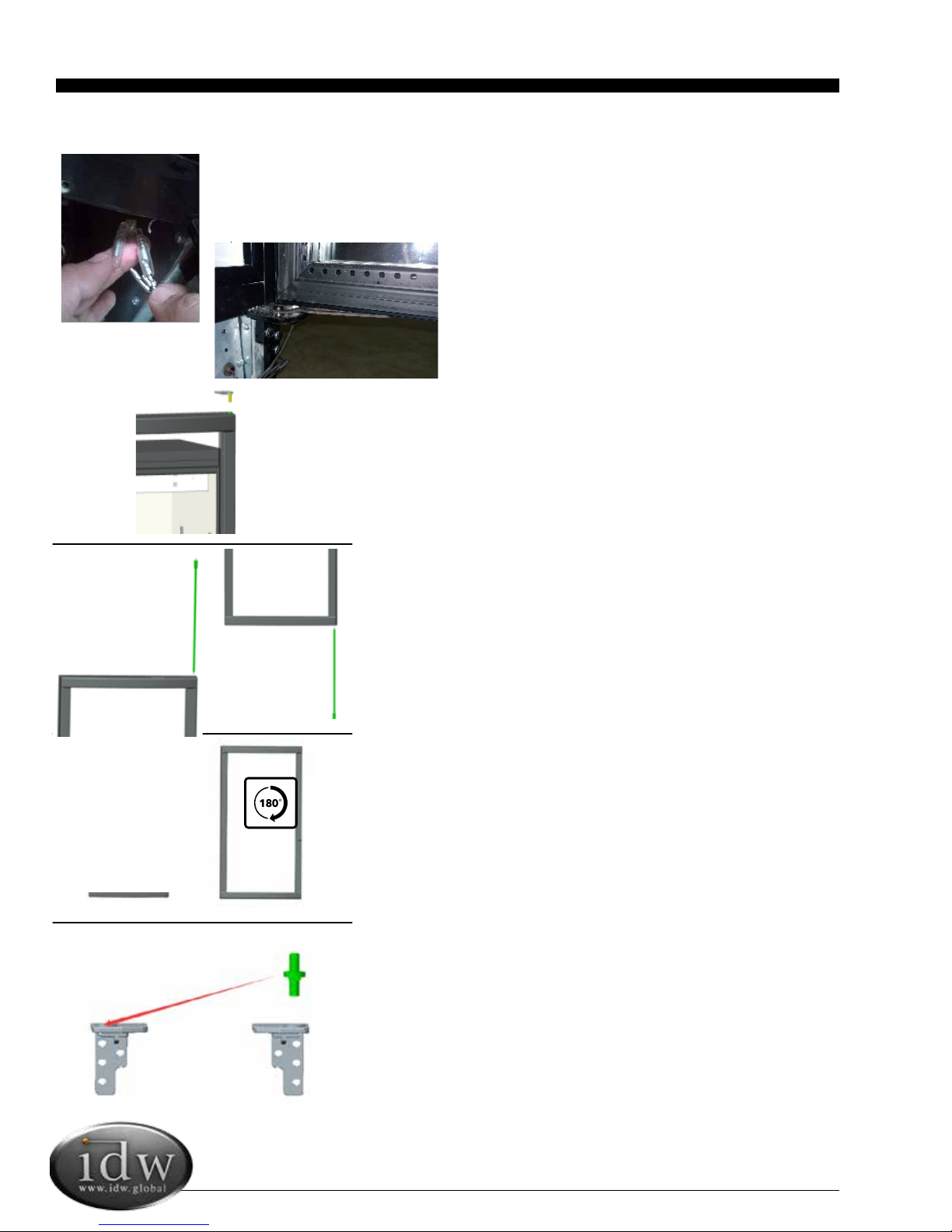
2Remove the right upper hinge and bottom door limit,then
remove the door.
3Take out the torsion rod from the upper right of the
door.
4Fishoutthewiringfromdoor’sreservedhole,the
wiringstretchesoutfromtheupperrightofdoor.
5Insert the torsion rod into corresponding holes on
bottom right of the door.
6Rotatethedoorclockwise180°,sothewiringis
stretching out from the bottom left of the door.
7Removethehingeaxisfromtherightbottomhinge,
inert it into the left bottom hinge.
DOOR REVERSAL (For G-10f Coolers Only)
11
reversibledoorexchange
7.TheterminalsofdoorLEDlightswiringistakenoutfrom
door'sreservedhole thengetthroughhingeaxie connect
6.drawoutthehingeaxisfromrightbottomhinge,insert
itintoleftbottomhinge.
3.disassembletherightupperhinge,thenremovethe
door.
1.disassemblethethehingelatchoflefthanddoor.
2.disassemblethefrontgrill,disconnecttheterminals,
thenhidetheterminalsintodoor'sreservedhole.
4.drawoutthestructureofselfclosingdoor,then
assemblethestructureintodoorotherside.
5.clockwiserotatethedoor180°.
No. change
Correction:
38 Electric Box Cover
47 Upper Compressor Baseboard
Delete clause 1 in the left and adjust the
rest clause Seiral No and content as below:
1.Remove the front grill, disconnect the
terminals and then hide the terminals in
the door's reserved hole.
2.Remove upper hinge and bottom door
limit,then remove the door.
remark: please add the above picture under
the No1 picture.
5
G10F/12F manual modification
1
2
Cancel the 2 holes for LED light switches
with labelling because the (2) LED light
switched are moved to compressor room back
3.Take out the torsion rod from the upper
of the door right
4.Fish out the wiring from door frame
cavity, the wiring stretches out from the
upper of door right.
5.Insert the torsion rod
into corresponding
holes on bottom right of the door.
6.Rotate the door clockwise 180°(Now the
wiring is stretching out from the bottom

Innovative DisplayWorks
G-10f/GCG-10f
8Remove door limit from right hinge into corresponding
holes on left hinge.
9Feedthewiringterminalsthroughthehingeandconnect
the terminals.
10Reinstallthetorsionrodintothenew
positionofthedooraxis.
11Settheupperhingeintothetorsionrodatapproximatelya
60°angle.Rotatethehingetotherightcounter-clockwise
aligningtheholesinthebracketwiththeholesontopof
the cabinet.
12 Install the limit to the door. Installing sequence—the
wavewasher—gasket-limit-bolt
13 Check to ensure the door is securely attached and
functioning properly.
14 Attachthefrontgrilltocompletethedoorreversal
process.
DOOR REVERSAL Cont. (For G-10f Coolers Only)
12
door sreservedhole,thengetthroughhingeaxie,connect
theterminals.
10.assemblethefrontgrill,completethereversibledoor
exchange.
9.fixtheupperhingeintoleftaxiesleeve,then
anticlockwiserotatethehingetorightpositiontofasten
it.
8.clockwiserotatetheleftaxiesleeve60°.
8.Remove door limit from right hinge into
corresponding holes on left hinge
9.Feed the wiring terminals through the
hinge and connect the terminals.
12.Install the limit to the door.
Installing sequence:the wave
washer—gasket-limit-bolt
6
7
10. Reinstall the torsion rod into the new
position of the door axis.
11. Set the upper hinge into the torsion
rod at approx a 60°angle. Rotate the hinge
to the right counter clockwise aligning the
holes in the bracket with the holes on top
of the cabinet.
wiring is stretching out from the bottom
of the door left
7. Remove the hinge axis from the right
bottom hinge, inert it into the left bottom
hinge.
Instruction Manual
13
Add the first clause
REPLACING THE FUSE
Add the first clause
REPLACING THE FUSE
REPLACING THE FUSE
1Unplug the cooler.
2 Removethescrewsfromthebackgrill,andthenremoveit.
3 Openthecoverofthefuseblock,asshownintheimagetotheleft.
4 Unscrewthefusebox,thenreplacethebadfuse.
5 Afterrepair,re-installallpartsreversingsteps1-5.
TROUBLESHOOTING
The following are not Malfunctions:
Issues Solutions
Liquid fl owing noise within cooler This liquid is the sound of the cooling agent fl owing through the pipes.
Refrigeration system is shutdown for
longer periods of time while temperature
inside is still very low.
This refrigerator has a strong level of heat preservation and can main-
tain a relatively ambient temperature.
Condensation on glass door This may be due to a high indoor humidity or a low inside temperature
value may be set. Wipe the door dry with a towel.
1This refrigerator has been designed and manufactured according to National standards. If there are any questions
during use, refer to this operation manual to help troubleshoot problems.
2When disposing of the cooler, please remove the door and lock assembly to avoid children accidentally becoming
trapped inside the cooler.
AFTER SALES SERVICE
Any product has the possibility of malfunction. Please observe the cooler’s operation and any changes to product being
stored. If there are any abnormal cases, refer to the table below. If there is still no change after following the below
instructions, please inform our service center in a timely manner to avoid a further loss of the unit.
Issues Solutions
Cooler is not functioning. Please check power supply:
• Fuse damage
• The plug is not securely inserted into the wall socket
• Check for low voltage
Cooler is not keeping product cool. • Provide ample space between all products to ensure proper
circulation of air.
• Keep unit away from direct sunlight or other heating source.
• Keep door closed as often as possible.
• Be certain cooler is not touching external objects or walls.
Excessive noise • Be certain the cooler is placed on a level surface.
• Be certain cooler is not touching external objects or walls.

Innovative DisplayWorks
G-10f/GCG-10f
14
TROUBLESHOOTING
The following are not Malfunctions:
Issues Solutions
Liquid fl owing noise within cooler This liquid is the sound of the cooling agent fl owing through the pipes.
Refrigeration system is shutdown for
longer periods of time while temperature
inside is still very low.
This refrigerator has a strong level of heat preservation and can main-
tain a relatively ambient temperature.
Condensation on glass door This may be due to a high indoor humidity or a low inside temperature
value may be set. Wipe the door dry with a towel.
1This refrigerator has been designed and manufactured according to National standards. If there are any questions
during use, refer to this operation manual to help troubleshoot problems.
2When disposing of the cooler, please remove the door and lock assembly to avoid children accidentally becoming
trapped inside the cooler.
AFTER SALES SERVICE
Any product has the possibility of malfunction. Please observe the cooler’s operation and any changes to product being
stored. If there are any abnormal cases, refer to the table below. If there is still no change after following the below
instructions, please inform our service center in a timely manner to avoid a further loss of the unit.
Issues Solutions
Cooler is not functioning. Please check power supply:
• Fuse damage
• The plug is not securely inserted into the wall socket
• Check for low voltage
Cooler is not keeping product cool. • Provide ample space between all products to ensure proper
circulation of air.
• Keep unit away from direct sunlight or other heating source.
• Keep door closed as often as possible.
• Be certain cooler is not touching external objects or walls.
Excessive noise • Be certain the cooler is placed on a level surface.
• Be certain cooler is not touching external objects or walls.
Instruction Manual
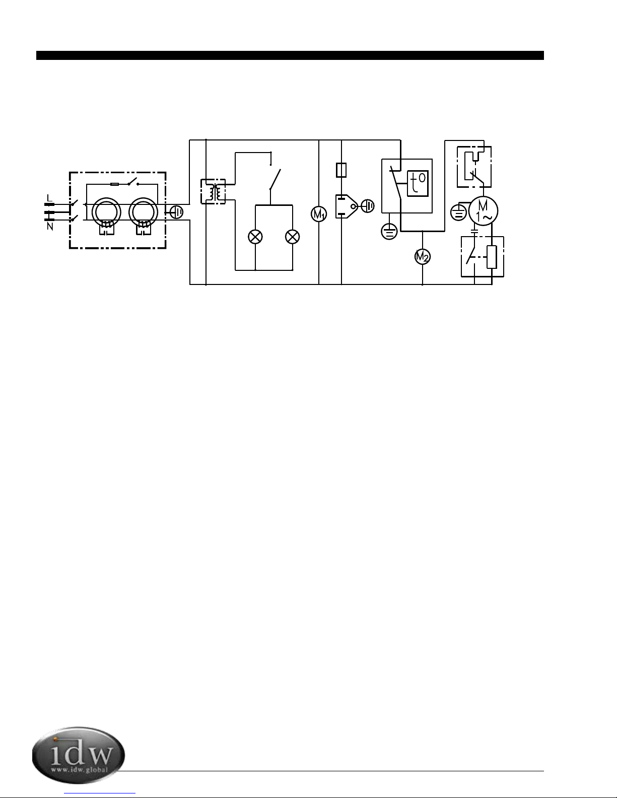
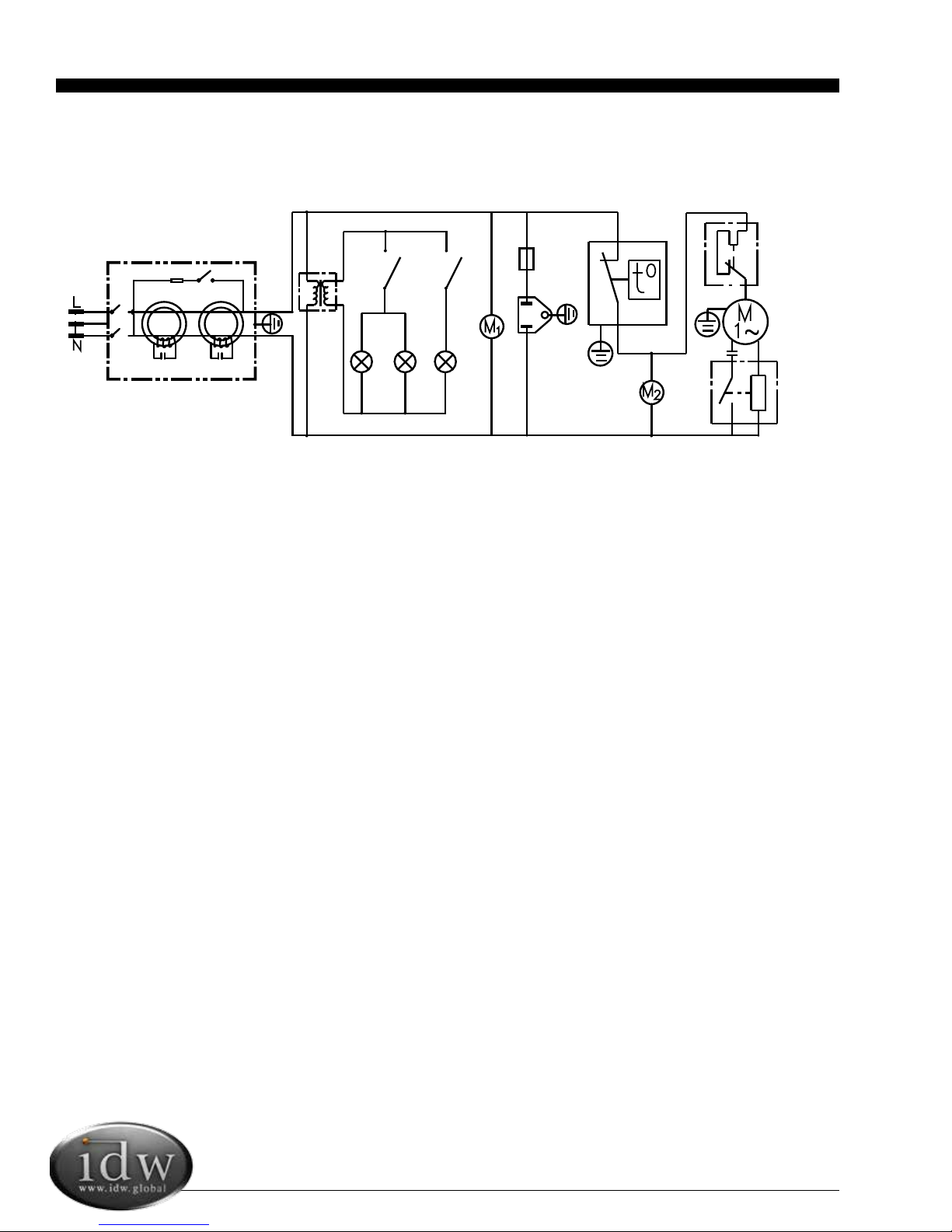
G-10f CIRCUIT DIAGRAM
15
ABC
D1 D2
E
F
E
G
H
I
J
K
L
M
A: Electric leakage protector
B: Power supply for LED lights
C: On/Off switch for interior and door side light
D1: Interior top LED light
D2: Door side LED light
E: Evaporator Fan
F: Fuse
G: Socket
H: Thermostat
I: Condenser fan
J: Overload for compressor
K: Compressor
L: Compressor starting capacitor
M: Compressor relay

Innovative DisplayWorks
G-10f/GCG-10f
16
G-10f ELECTRICAL WIRING DIAGRAM
DOOR SIDE LED LIGHT
INNER TOP LED LIGHT
BK
RD
BK WH
WH
BK
EVAPORATOR FAN
BK RD
WH
WH
BK
BK
TEMPERATURE
CONTROL
CONDENSER UNIT
WH
BK AC 125V 3A
FUSE
SOCKET
SWITCHING
POWER SUPPLY
INTERIOR
LIGHT SWITCH
RD
CONNECTIONS FOR EMI70UER COMPRESSOR
POWER CORD
GN
WH
WH
BK
RD
BK
WH
L1
L2
N
TERMINAL BOX
TO HARNES
GROUND
WH
RD
START CAPACITY
BK
S
R
21
RELAY
C
1
WH
3
2
CONDENSER FAN
CONTROL UNIT
TO SOCKET
GN
WH
BK
Instruction Manual
17
GCG-10f CIRCUIT DIAGRAM
ABC1 C2
D1 D2 D3
E
F
E
G
H
I
J
K
L
M
D3: Door LED Logo Light
E: Evaporator fan
F: Fuse
G: Socket
H: Thermostat
I: Condenser fan
A: Electric leakage protector
B: Power supply for LED lights
C1: On/Off switch for Interior light
C2: On/Off switch for lit door logo light
D1: Interior top LED light
D2: Door side LED light
J: Overload for Compressor
K: Compressor
L: Conpressor starting capacitor
M: Compressor relay

Innovative DisplayWorks
G-10f/GCG-10f
18
GCG-10f ELECTRICAL WIRING DIAGRAM

Innovative DisplayWorks, Inc.
To locate the distributor in your area go to: http://www.idw.global/contact/#distributors
This manual suits for next models
8
Table of contents
Other IDW Freezer manuals


