IEF Werner miniSPIN User manual

Translation of the original instructions | EN
IEF-Werner GmbH | Wendelhofstraße 6 | DE-78120 Furtwangen | www.ief-werner.de
Operating Instructions
Product name:
miniSPIN
Product ID:
1416190


miniSPIN
Translation of the original instructions | EN 3 - 45
IEF-Werner GmbH | Wendelhofstraße 6 | DE-78120 Furtwangen | www.ief-werner.de
Generated by: Reichelt Frank | MAN_EN_1416190_miniSPIN_R1b.doc
Use
■The operating instructions must be available at the component at all times.
■The operating instructions must be available at the component/device at all times.
■Always use the complete original (or the original translation) of these operating instructions.
Supplier & Manufacturer
IEF-Werner GmbH
Wendelhofstraße 6
DE-78120 Furtwangen - Germany
Phone: 07723-925-0
Telefax: 07723-925-100
www.IEF-Werner.de
info@IEF-Werner.de
Service
Find your IEF service station on our website:
■http://www.ief-werner.de
Legal Note
All rights, including translation, reserved. No part of the work must be reproduced in any manner
(print, copy, microfilm or other method) without the written consent of IEF Werner GmbH or
processed, reproduced or distributed using electronic systems.
All rights reserved for the case of patent, utility sample or design patent entry reserved.
© September 2018, IEF-Werner GmbH, printed in Germany

miniSPIN
4 - 45 Translation of the original instructions | EN
IEF-Werner GmbH | Wendelhofstraße 6 | DE-78120 Furtwangen | www.ief-werner.de
Generated by: Reichelt Frank | MAN_EN_1416190_miniSPIN_R1b.doc
History of Changes
Document Code Date Modification
MAN_EN_1416190_miniSPIN_R1a.doc January 2018
English release according to original
instructions in German (MAN_DE_1090932_
miniSPIN_R1b.doc)
MAN_EN_1416190_miniSPIN_R1b.doc September
2018
Addition of gear ratios (lever/quill) in
section 5.4.1: Technical Data for the
miniSPIN-Series, page 27.
Trademarks and trade names are used without any warranty of their free usability. Texts and
examples have been created with great care. Nevertheless, errors cannot be excluded. IEF Werner
GmbH does not assume legal responsibility nor any liability for missing or incorrect statements or
their consequences.
IEF Werner GmbH reserves the right to modify or improve the software or hardware or parts of it,
as well as the supplied documentation or parts of it, without previous notice.
We are always grateful for suggestions for improvements and information about errors.

miniSPIN
Translation of the original instructions | EN 5 - 45
IEF-Werner GmbH | Wendelhofstraße 6 | DE-78120 Furtwangen | www.ief-werner.de
Generated by: Reichelt Frank | MAN_EN_1416190_miniSPIN_R1b.doc
Table of Contents
1Declaration of Incorporation ................................................................................... 7
2Safety........................................................................................................................... 9
2.1 Definition of Warning Notes ........................................................................................ 9
2.2 General Warning Notes .............................................................................................. 10
2.3 Special Hazard Warnings ........................................................................................... 11
3Intended Use ............................................................................................................ 13
3.1 Reasonably Foreseeable Misuse .............................................................................. 13
4Function and Description ....................................................................................... 15
4.1 Function......................................................................................................................... 15
4.1.1 Function miniSPIN-Component "Mono"...................................................... 15
4.1.2 Function miniSPIN-Component "Twin" ........................................................ 16
4.2 Combination Options/Specifications ........................................................................ 17
4.3 Description of the Main Assemblies......................................................................... 18
4.3.1 Main Assemblies of the Components miniSPIN "Mono".......................... 18
4.3.2 Main Assemblies of the Components miniSPIN "Twin"............................ 19
4.4 Description of the Blowing Air or Vacuum Progress.............................................. 20
5Assembly Instructions............................................................................................. 23
5.1 Installation Position ..................................................................................................... 23
5.2 Attachment ................................................................................................................... 24
5.2.1 Assembly Plate for miniSPIN "Mono" .......................................................... 24
5.2.2 Assembly Plate for miniSPIN "Twin" ............................................................ 24
5.2.3 Actuators for miniSPIN "Mono" and "Twin" ................................................ 25
5.3 Transverse Installation................................................................................................ 26
5.4 Technical Data ............................................................................................................. 27
5.4.1 Technical Data for the miniSPIN-Series ...................................................... 27
6Troubleshooting ....................................................................................................... 29
7Parts Lists and Drawings ....................................................................................... 30
7.1 miniSPIN "Mono" in the Standard Version .............................................................. 30
7.1.1 Swivel Arm cpl. Type 151.5 mm, Part No.: 1306274................................. 32
7.1.2 Swivel Arm cpl. Type 87 mm, Part No.: 1301303 ...................................... 34
7.1.3 Swivel Arm cpl. Type 52.5 mm, Part No.: 1301291 ................................... 36
7.1.4 Rotary Penetration Single cpl., Part No.: 1301351 .................................... 38
7.1.5 Lifting Suction Quill cpl., Part No.: 1306279 ............................................... 39
7.2 miniSPIN "Twin" in the Standard Version ................................................................ 40
7.2.1 Swivel Arms ..................................................................................................... 41
7.2.2 Rotary Penetration Double cpl., Part No.: 1301379 .................................. 42
7.2.3 Gripper cpl., Part No.: 1306282 .................................................................... 44
7.2.4 Double Washer cpl., Part No.: 1301337 ...................................................... 45


miniSPIN
Translation of the original instructions | EN 7 - 45
IEF-Werner GmbH | Wendelhofstraße 6 | DE-78120 Furtwangen | www.ief-werner.de
Generated by: Reichelt Frank | MAN_EN_1416190_miniSPIN_R1b.doc
1Declaration of Incorporation
Within the meaning of the directive 2006/42/EC on machinery according to Annex II, 1. B.
Manufacturer: IEF-Werner GmbH
Wendelhofstraße 6
D-78120 Furtwangen - Germany
Components: miniSPIN "Mono" (one NC-motor),
Actuator force-controlled
miniSPIN Twin (two NC-motors),
Actuator as NC-rotating axis
Documentation officer: Frank Reichelt
The manufacturer confirms that the above component corresponds to the following
basic requirements of the machinery directive 2006/42/EC:
Annex I, item: 1.1.2; 1.1.3; 1.1.5; 1.3.2; 1.3.4; 1.5.1; 1.7.3; 1.7.4;
The technical documents were generated according to Annex VII part B and may be
electronically submitted to the national authorities upon justified request.
The following further directives have been applied:
■EMC directive 2014/30/EC
The following harmonised standards have been applied:
■EN ISO 12100
■EN 1037
■EN 692
■EN 60204-1
■EN ISO 13849-1/-2
■EN ISO 13857
■EN ISO 13732-1
■EN 61310-1/-2
■EN ISO 13850
■EN 953
■EN 14070
The following other technical standards and specifications have been applied:
■VDI 2854 ■DIN 4844-2 ■EN 60947-5/-6
Commissioning of the component is forbidden until it has been determined that the
machine into which the component is to be installed corresponds to the provisions of the
machinery directive 2006/42/EC.
Furtwangen, January 2018 Manfred Bär (manager)


miniSPIN
Translation of the original instructions | EN 9 - 45
IEF-Werner GmbH | Wendelhofstraße 6 | DE-78120 Furtwangen | www.ief-werner.de
Generated by: Reichelt Frank | MAN_EN_1416190_miniSPIN_R1b.doc
2Safety
2.1 Definition of Warning Notes
DANGER
Indicates danger.
Non-observance of the safety provisions causes death.
WARNING
Indicates potential danger.
Non-observance of the safety provisions may cause death or severe injury.
ATTENTION
Indicates potential danger.
Non-observance of the safety provisions may cause injury.
CAUTION
Indicates potential danger. Non-observance of the safety provisions may cause property damage.
miniSPIN
10 - 45 Translation of the original instructions | EN
IEF-Werner GmbH | Wendelhofstraße 6 | DE-78120 Furtwangen | www.ief-werner.de
Generated by: Reichelt Frank | MAN_EN_1416190_miniSPIN_R1b.doc
2.2 General Warning Notes
The miniSPIN component must only be commissioned by specialists who have received safety-
technical instruction and are able to assess potential dangers.
Furthermore, all chapters of this operating manual must have been read and understood
completely.
DANGER
Warning of dangerous electrical voltage.
The component must be powered down for all assembly, disassembly or repair work.
Non-observance of the safety provisions may cause death.
WARNING
miniSPIN-components must always be operated with protective
devices.
The miniSPIN-component always has to be operated in connection with suitable safety
devices (e.g., safety cell, protective room, protective housing, light curtain).
ATTENTION
Do not remove plugs or clamps when live.
Motor connectors or clamps must not be inserted or disconnected when live. Risk of
burning of the contacts and risk of flying sparks.
ATTENTION
Warning of hot surface.
During operation, the heated drive/cover may cause skin burns if touched. Install a
protective device, if possible! Do not touch the marked areas or wait for an adequate
cooling time.
Observe the Declaration of Incorporation (see section Declaration of Incorporation, page 7).

miniSPIN
Translation of the original instructions | EN 11 - 45
IEF-Werner GmbH | Wendelhofstraße 6 | DE-78120 Furtwangen | www.ief-werner.de
Generated by: Reichelt Frank | MAN_EN_1416190_miniSPIN_R1b.doc
2.3 Special Hazard Warnings
In addition, this Original User's Manual also contains the following special hazard warnings:
WARNING
Warning of crushing of limbs.
These points of the components pose the danger of crushing of limbs (finger/hand) in
operation.
ATTENTION
Warning of hot surface.
During operation, the heated drive/cover may cause skin burns if touched. Install a
protective device, if possible! Do not touch the marked areas or wait for an adequate
cooling time.
Figure 1 Danger points at the miniSPIN-components (a)
miniSPIN
12 - 45 Translation of the original instructions | EN
IEF-Werner GmbH | Wendelhofstraße 6 | DE-78120 Furtwangen | www.ief-werner.de
Generated by: Reichelt Frank | MAN_EN_1416190_miniSPIN_R1b.doc
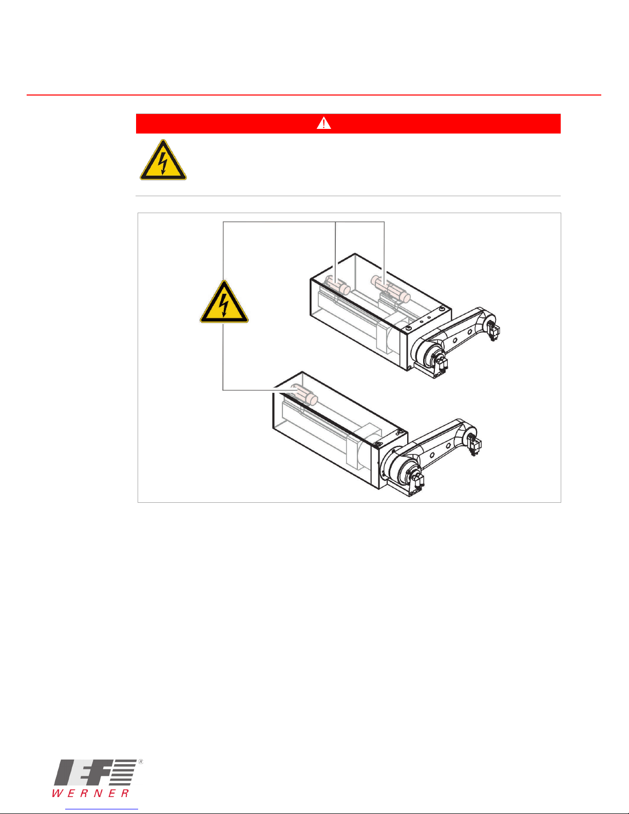
DANGER
Warning of dangerous electrical voltage.
The component must be powered down for all assembly, disassembly or repair work.
Non-observance of the safety provisions may cause death.
Figure 2 Danger points at the miniSPIN-components (b)

miniSPIN
Translation of the original instructions | EN 13 - 45
IEF-Werner GmbH | Wendelhofstraße 6 | DE-78120 Furtwangen | www.ief-werner.de
Generated by: Reichelt Frank | MAN_EN_1416190_miniSPIN_R1b.doc
3Intended Use
The miniSPIN-component is a compact handling unit with highly dynamic properties.
The concept has been adjusted to positioning of small parts with a weight of up to 20 g.
Typical Pick & Place processes can be implemented with a total cycle time of 240 ms.
The miniSPIN-component can be used both as a single station and in combination with linear units.
In conjunction with directly powered linear axes (e.g. the IEF-Werner component "euroLINE"), highly
dynamic handling systems can be implemented,−e.g. for processing product ranges−.
Standardised lever lengths are available in order to permit optimal use of the miniSPIN-
components.
Figure 3 miniSPIN components "Mono" and "Twin"
Areas of use of the miniSPIN-components include:
■Review/contacting of parts
■Quick handling of parts with up to 20 grams dead weight (clocks, glass, electrical parts,
precision mechanics)
■As Vision System (also overhead)
■To swivel parts from the horizontal into the vertical position
■etc.
3.1 Reasonably Foreseeable Misuse
The miniSPIN-components are not to be used for certain applications such as the transport of
persons and animals or as a pressing/bending device.
Use of the miniSPIN-components without additional measures is also not possible in special fields
of application, such as the chemical or food industry or in explosive atmospheres.
In case of doubt, consult the manufacturer.


miniSPIN
Translation of the original instructions | EN 15 - 45
IEF-Werner GmbH | Wendelhofstraße 6 | DE-78120 Furtwangen | www.ief-werner.de
Generated by: Reichelt Frank | MAN_EN_1416190_miniSPIN_R1b.doc
4Function and Description
4.1 Function
4.1.1 Function miniSPIN-Component "Mono"
The miniSPIN-component "Mono" turns around 180°. The actuator (suction or gripper) remains in
the vertical position at all times while swivelling.
Figure 4 Function of the miniSPIN-component "Mono"

miniSPIN
16 - 45 Translation of the original instructions | EN
IEF-Werner GmbH | Wendelhofstraße 6 | DE-78120 Furtwangen | www.ief-werner.de
Generated by: Reichelt Frank | MAN_EN_1416190_miniSPIN_R1b.doc
4.1.2 Function miniSPIN-Component "Twin"
The miniSPIN-component "Twin" turns around 180°. The actuator (suction or gripper) can take a
position/orientation defined by you while turning.
Figure 5 Function of the miniSPIN-component "Twin"

miniSPIN
Translation of the original instructions | EN 17 - 45
IEF-Werner GmbH | Wendelhofstraße 6 | DE-78120 Furtwangen | www.ief-werner.de
Generated by: Reichelt Frank | MAN_EN_1416190_miniSPIN_R1b.doc
4.2 Combination Options/Specifications
The following combination options/specifications are possible:
Rotary penetration Actuator Turnability
1 motor
Simple rotary penetration
Suction
Suction (vertical)
Double rotary penetration
Gripper
Gripper (vertical)
2 motors
Double rotary penetration Suction Suction (turning)
Double rotary penetration
Gripper
Gripper (turning)
Figure 6 Combination options
■1 motor/single rotary penetration:
→only suction possible (no gripper), actuator (suction) always vertical
■1 motor/double rotary penetration:
→only gripper possible (no suction), actuator (gripper) always vertical
■2 motors/single rotary penetration:
→only suction possible (no gripper), actuator (suction) can turn
■2 motors/double rotary penetration:
→only gripper possible (no suction), actuator (gripper) can turn
miniSPIN
18 - 45 Translation of the original instructions | EN
IEF-Werner GmbH | Wendelhofstraße 6 | DE-78120 Furtwangen | www.ief-werner.de
Generated by: Reichelt Frank | MAN_EN_1416190_miniSPIN_R1b.doc
4.3 Description of the Main Assemblies
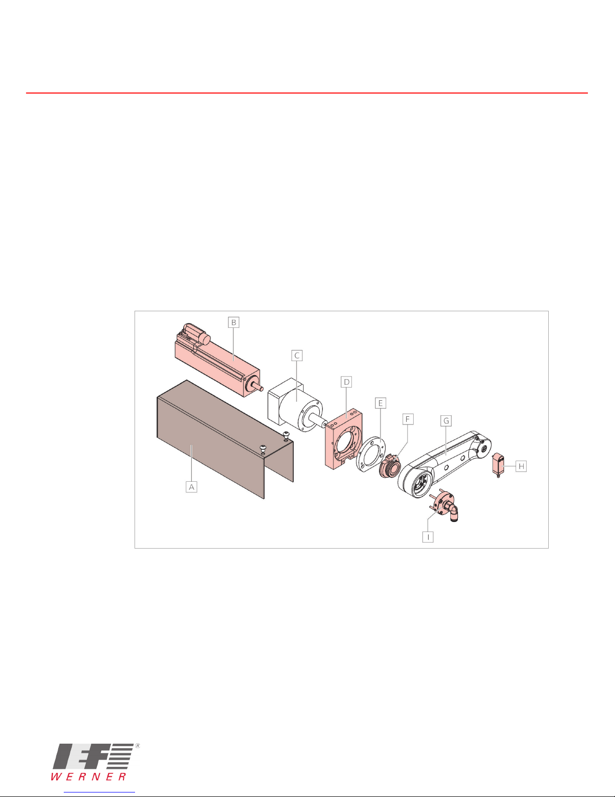
4.3.1 Main Assemblies of the Components miniSPIN "Mono"
The main assemblies of the component miniSPIN "Mono" are
(example: Simple rotary penetration with suction):
■Cover sheet
■Servo motor with brake and plug
■Planetary gear
■Assembly plate
■Clamping disc, single disc, cover clamping ring
■Swivel arm complete
■Lifting suction quill complete
■Rotary penetration single, complete
Figure 7 Main assemblies of the component miniSPIN "Mono"
ACover sheet B Servo motor with brake and plug
CPlanetary gear D Assembly plate
ECover of clamping ring F Clamping disc and single disc
GSwivel arm complete H Lifting suction quill complete
IRotary penetration single, complete
Note: For more information on important subassemblies, see section Parts Lists and Drawings,
starting at page 30.
miniSPIN
Translation of the original instructions | EN 19 - 45
IEF-Werner GmbH | Wendelhofstraße 6 | DE-78120 Furtwangen | www.ief-werner.de
Generated by: Reichelt Frank | MAN_EN_1416190_miniSPIN_R1b.doc
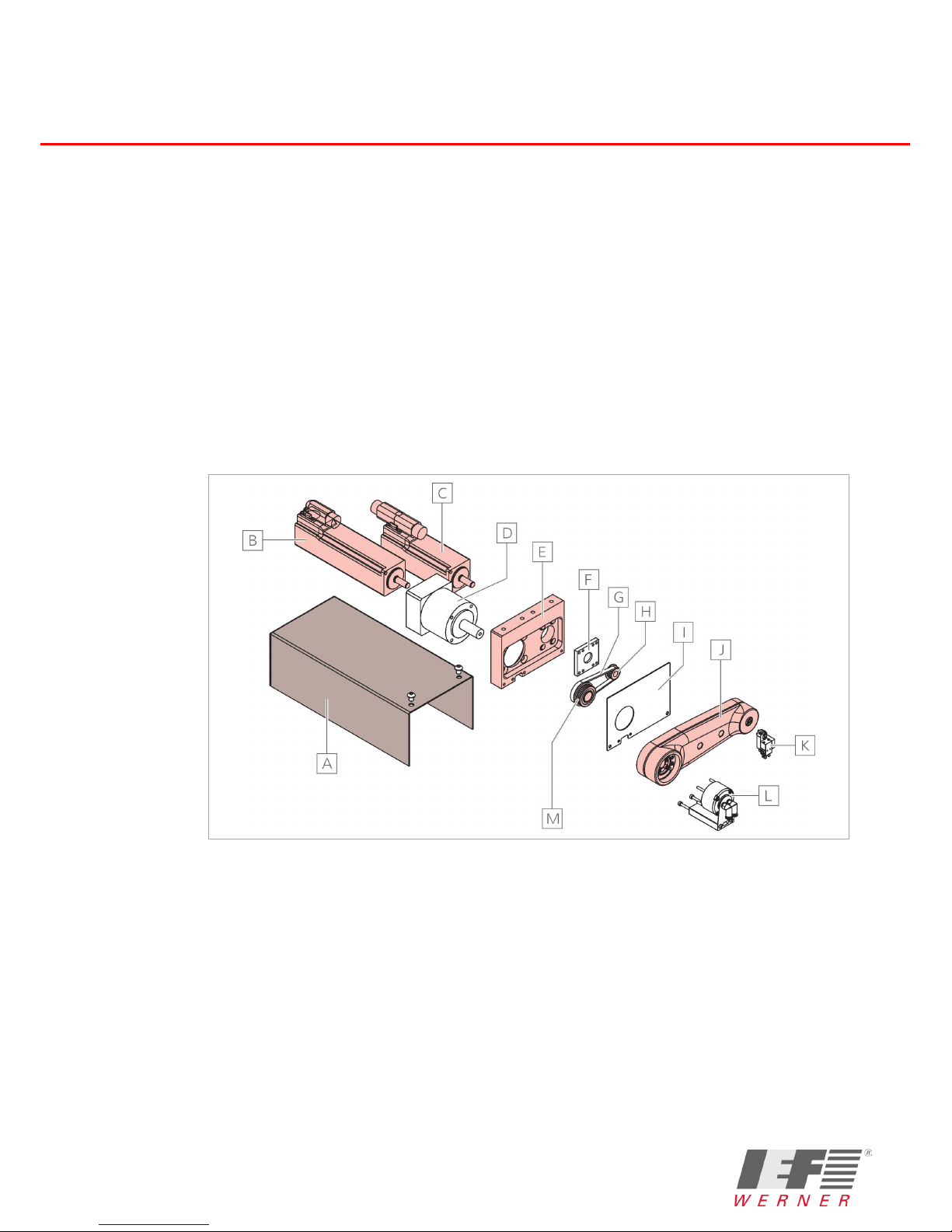
4.3.2 Main Assemblies of the Components miniSPIN "Twin"
The main assemblies of the component miniSPIN "Twin" are
(example: Double rotary penetration with gripper):
■Cover sheet
■Servo motors with brake and plugs
■Planetary gear
■Assembly plate
■Interim flange
■Double washer, complete
■Pinion
■Swivel arm complete
■Gripper quill, complete
■Rotary penetration double, complete
Figure 8 Main assemblies of the component miniSPIN "Twin"
ACover sheet B Servo motor with brake and plug
for swivel arm movement
CServo motor with brake and plug
for quill movement
DPlanetary gear
EAssembly plate F Interim flange
GToothed belt H Pinion
ICover plate J Swivel arm complete
KGripper quill, complete L Rotary penetration double, complete
MDouble washer, complete
Note: For more information on important subassemblies, see section Parts Lists and Drawings,
starting at page 30.

miniSPIN
20 - 45 Translation of the original instructions | EN
IEF-Werner GmbH | Wendelhofstraße 6 | DE-78120 Furtwangen | www.ief-werner.de
Generated by: Reichelt Frank | MAN_EN_1416190_miniSPIN_R1b.doc
4.4 Description of the Blowing Air or Vacuum Progress
The following figures show the blowing air or vacuum progress.
Rotary penetration single, with lifting suction quill
Figure 9 Blowing air or vacuum progress for lifting suction quill
Table of contents
Popular Industrial Electrical manuals by other brands

Giovenzana
Giovenzana TR85H7PW Mounting instructions

Murata
Murata GRM0335C1HR40WA01 Series Reference sheet

Lindy
Lindy T568A Installation instruction

Murata
Murata GQM2195C2A9R1CB01 Series Reference sheet

Murata
Murata GRM1555C1H2R7CA01 Seies Reference sheet

Murata
Murata GRM0225C1E6R4BA03 Series Reference sheet

Siemens
Siemens 3VA9988-0BM10 operating instructions

Murata
Murata GRM31CR61E106KA12 Series Reference sheet

Murata
Murata GRM32AR61C106KAB7 Series Reference sheet

Murata
Murata GRM21A7U1H333JA39 Series Reference sheet

Murata
Murata GRM219R61E225KA12 Series Reference sheet

PCB Piezotronics
PCB Piezotronics IMI SENSORS M635A01 Installation and operating manual


