IFM RM30 Series Reference guide

706414/00 Page 1 of 14 © ifm efector gmbh
RM30xx Profibus
Brief instructions
efector400

706414/00 Page 2 of 14 © ifm efector gmbh
Contents
The description may contain deviations from the user system, because different
manufacturers or software versions may require different installations!
The description was created based on Siemens S7 version V5.4 + SP4.
1Installation ................................................................................................................................. 3
1.1Software...................................................................................................................................3
1.2Hardware .................................................................................................................................4
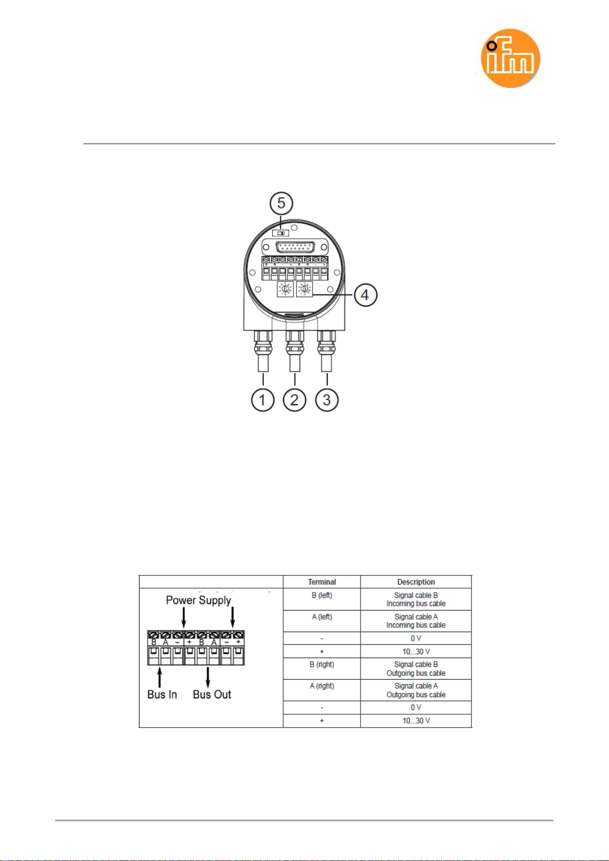
1.2.1Overview...........................................................................................................................4
1.2.2Connection .......................................................................................................................4
2Setting the encoder function:.................................................................................................. 6
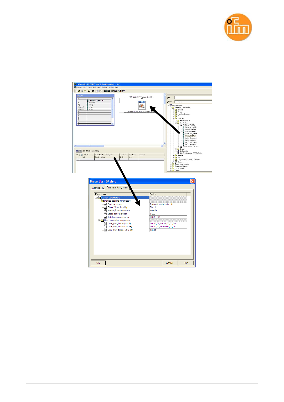
2.1Selection of the correct encoder:.............................................................................................6
2.2Multiturn encoder Class2 (standard): ...................................................................................... 7
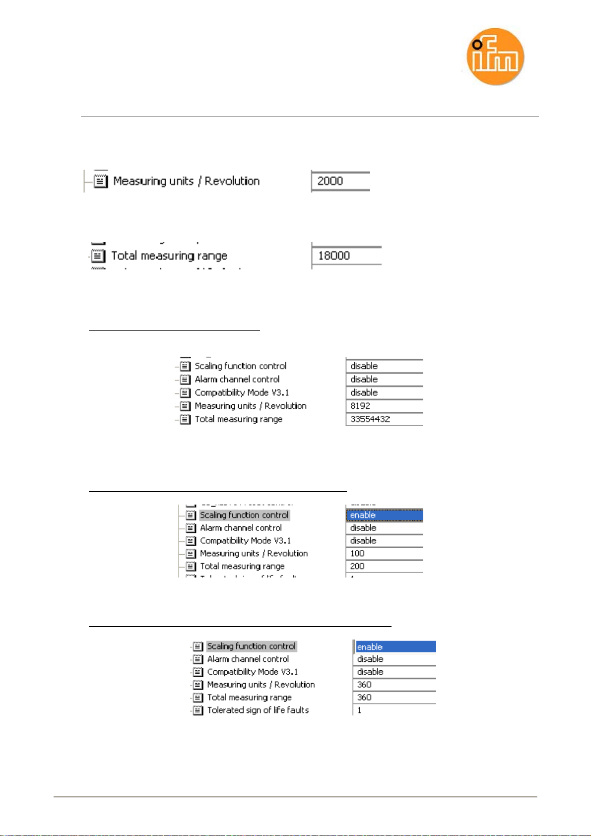
3Setting of the measuring units (measuring range):............................................................... 8
3.1Setting examples.....................................................................................................................9
3.2Setting examples with high and low word.............................................................................. 10
4Hex parameter setting for multiturn class 2:........................................................................ 11
5List of variables, reset and preset......................................................................................... 12
5.1Display variables....................................................................................................................12
5.2Reset:.....................................................................................................................................13
5.3Preset:....................................................................................................................................13
6Other:........................................................................................................................................ 14
Safety instructions
Please read the product description prior to set-up of the unit. Ensure that the product is suitable for
your application without any restrictions.
The unit complies with the relevant regulations and EC directives.
Improper or non-intended use may lead to malfunctions of the unit or to unwanted effects in your
application.
That is why installation, electrical connection, set-up, operation and maintenance of the unit must be
carried out by qualified personnel authorised by the machine operator.

706414/00 Page 3 of 14 © ifm efector gmbh
1 Installation
1.1 Software
1. Download the GSD file from www.ifm.com => Article => [More information] => [Software
download] => Device master data (GSD) file
Example: RM3006 [gsd-DPV0]*
2. Hardware catalogue => Install GSD (first, unzip the ZIP file)
3. Additional Field Devices => Encoder, select ifm Encoder (see chapter 2)
4. Drag the encoder into the project and assign a Profibus address
5. Parameter setting of the encoder (see chapter 3)
6. Set the requested variables (see chapter 5)
*DP-V0: cyclic exchange of data and diagnoses (standard)

706414/00 Page 4 of 14 © ifm efector gmbh
DP-V2: isochronous data exchange, lateral communication between the slaves and time
synchronisation.
1.2 Hardware
1.2.1 Overview
1: voltage supply +Ub /-GND
2: bus IN
3: bus OUT
4: addressing
5: terminating resistor
1.2.2 Connection

706414/00 Page 5 of 14 © ifm efector gmbh

706414/00 Page 6 of 14 © ifm efector gmbh
2 Setting the encoder function:
2.1 Selection of the correct encoder:
Class1 Singleturn:
This setting enables only the setting of the direction of rotation at max. 8192 measuring units.
Class1 Multiturn:
This setting enables only the setting of the direction of rotation at max. 8192 measuring units x 4096
revolutions.
Class2 Singleturn:
This setting enables the setting of the direction of rotation, diagnostic function and scaling of the
measuring units at 8192 units.
- Class2 Multiturn (standard):
This setting enables the setting of the direction of rotation, diagnostic function and scaling of the
measuring units at 8192 units x 4096 revolutions.
ifm 2.1 Singleturn / Multiturn
Additionally to Class2: limit switch function, set-up mode.
For details see operating instructions.
ifm 2.2 Singleturn / Multiturn
As in 2.1 but with provision of a speed value.
For details see operating instructions.
Hardware catalogue:

706414/00 Page 7 of 14 © ifm efector gmbh
2.2 Multiturn encoder Class2 (standard):
Configuration (HW Config) => DP Slave Properties => Assigning Parameters
Setting options:
Code sequence: Counterclockwise / clockwise
Class 2 functionality: Enable / disable
Scaling function control: Enable scaling / disable scaling
Measuring units per rev.: 8192 (factory setting)
Total measuring range: 33554432 (factory setting)

706414/00 Page 8 of 14 © ifm efector gmbh
3 Setting of the measuring units (measuring range):
Simplified representation:
Measuring units per rev.
Standard: 8192
Revolutions
Standard: 4096
The resolution per revolution are the pulses which are provided for a revolution. The
revolutions are the further pulses for another entire revolution.
Example: 8192 x 2 revolutions = total: 16384
(1,2,…8192, 8193,…16383, 16384,1,2,…)
Input of the figures:
Maximum units:
8192 units x 4096 revolutions => total measuring range 33 554 432
The revolutions must never be more than 4096, therefore the number of total measuring units
is irrelevant.
Example:
7096 units x 2048 revolutions = 14 532 608 total measuring range => OK.
196 units x 4097 revolutions = 803 012 total measuring range => not OK.
Integers:
Only integer values may be entered.
Example:
8192 units x 2.5 revolutions = 20 480 total measuring range => not OK.

706414/00 Page 9 of 14 © ifm efector gmbh
3.1 Setting examples
The value for the resolution (pulses for a revolution) must be entered for measuring units per
revolution:
The total measuring range must be calculated.
Example.: 2000 pulses x 9 revolutions = 18 000
Standard: Scaling function disabled
Resolution per revolution 8192 x revolutions 4096 = total measuring range 33 554 432
100 units x 2 revolutions (total measuring range 200):
360 units x 1 revolution (total measuring range 360 singleturn):

706414/00 Page 10 of 14 © ifm efector gmbh
3.2 Setting examples with high and low word
For some controllers the value for the total measuring range must be converted to a high
word and a low word.
Standard setting 8192 units x 4096 revolutions:
8192 units x 4096 revolutions => total measuring range 33 554 432
total measuring range 33 554 432 in hex => 0200 0000 hex
high word 0200 hex in decimal => 512
low word 0000 hex in decimal => 0
200 units x 24 revolutions - enable scaling:
200 units x 24 revolutions => total measuring range 4800
total measuring range 4800 in hex => 0000 12C0 hex
high word 0000 hex in decimal => 0
low word 12C0 hex in decimal => 4800
200 units x 1 revolution - enable scaling:
200 units x 1 revolution => total measuring range 200
total measuring range 200 in hex => 0000 00C8 hex
high word 0000 hex in decimal => 0
low word00C8hexindecimal =>200

706414/00 Page 11 of 14 © ifm efector gmbh
4 Hex parameter setting for multiturn class 2:
Hex parameter setting means that the device-specific parameters are written in HEX coding.
These settings do not have to be made if already set in the device-specific parameters.
Octet 9
Octet 10
Octet 11
Octet 12
Octet13
Octet14
Octet15
Octet16
Octet17
,02 (HEX - CODE)
0000 0010 (BINARY CODE)
Meaning (read from right to left):
Octet 9 bit 0 => 0 = clockwise // 1 counterclockwise
Octet 9 bit 1 => 0 = class 2 disable // 1class 2 enable
Octet 9 bit 2 => 0 = "optional" set-up diagnosis No // 1 Yes

706414/00 Page 12 of 14 © ifm efector gmbh
5 List of variables, reset and preset
5.1 Display variables
Simatic Manager => CPU 315-2 (select) TAB PLC => Monitor/control variable
Display measured value:
Operand ED 100 (for set input address 100...103), display format DEC, and monitor
variables.
Attention: When the properties are changed, a reset must be carried out to display
the current value.

706414/00 Page 13 of 14 © ifm efector gmbh
5.2 Reset:
Operand AD 100 (for set E address 100...103), display format HEX, enter 8 at the
first position in the control value (DW = Double Word) for a value change.
Only a change of the status value from 0 to 8 is detected; no value change is carried
out when the status value of 8 remains 8.
(Attention! Only to be carried out when the encoder is standing still)
Example reset:
OPERAND DISPLAY FORMAT STATUS VALUE CONTROL
VALUE
ED 100 Dec.. L#5120
AD 100 Hex.: DW#0000 0000 8000 0000
OPERAND DISPLAY FORMAT STATUS VALUE CONTROL
VALUE
ED 100 Dec.. L#0
AD 100 Hex.: DW#8000 0000 8000 0000
5.3 Preset:
Operand AD 100 (for set E address 100...103), display format HEX, enter 8 at the
first position in the control value (DW = Double Word) for a value change.
Only a change of the status value from 0 to 8 is detected; no value change is carried
out when the status value of 8 remains 8.
(Attention! Only to be carried out when the encoder is standing still)
Example Preset:
OPERAND DISPLAY FORMAT STATUS VALUE CONTROL
VALUE
ED 100 Dec.. L#0
AD 100 Hex.: DW#0000 0000 8000 0E10
OPERAND DISPLAY FORMAT STATUS VALUE CONTROL
VALUE
ED 100 Dec.. L#3600
AD 100 Hex.: DW#8000 0E10 8000 0E10
3600 (decimal) = 0E10 (hex)

706414/00 Page 14 of 14 © ifm efector gmbh
6 Other:
Byte: 1 2 3 4
Word 1: 8 0 0 0 0 0 0 0 HEX coding
Word0:
Bit: 1000 0000 0000 0000 0000 0000 0000 0000 BINARY CODING
Bit numbers:31…2827…24 23…20 19...16 15…12 11…8 7…4 3…0
Example decimal to binary:
8 bits = 1 byte = octet
16bits = 2 bytes = word
32bits = 4 bytes = double word (DWORD)
64bits = 8 bytes = quadruple word(LongWORD)
31 0
Word 1 Double word
15
Word 0
Multiturn Singleturn
This manual suits for next models
1
Table of contents
Other IFM Industrial Electrical manuals
Popular Industrial Electrical manuals by other brands

Intelitek
Intelitek Scorbot-ER 9 Pro installation guide

Murata
Murata GRM1885C2A4R0CA01 Series Reference sheet

Siemens
Siemens SIRIUS S00 Original operating instructions

Murata
Murata GQM1555C2D1R1BB01 Series Reference sheet

Murata
Murata LLA219R70J105MA01 Series Reference sheet

Greenheck
Greenheck AMD-42-TD Installation, operation and maintenance manual