IGBT CO2 User manual

Full Digital Heavy Duty IGBT CO2/MAG/MMA Carrier
Intelligent Multifunctional Inverter Welder
User Manual
Version: V1.4
No.: R33010063
Shenzhen Megmeet Electric Co., Ltd. provides comprehensive technical support for customers,
covering but not limited to, CAN communication, welder network monitors, robot collaboration,
welding process database software upgrade, and after-sale service. Users can contact the nearest
Megmeet's offices or customer service centers, or directly contact Megmeet headquarters.
Shenzhen Megmeet Electric Co., Ltd.
All rights reserved. The content may subject to change without notice.
Shenzhen Megmeet Electric Co., Ltd.
Address: 5th Floor Block B, Ziguang Information Harbor, Langshan Road, Shenzhen, 518057,
China
Zip code: 518057
Website: www.megmeet.com
Customer service hotline: 4006662163
Email: Welder.4S@megmeet.com

Preface
Thank you for choosing Megmeet's full digital heavy duty IGBT CO2/MAG/MMA carrier intelligent
multifunctional inverter welder (hereinafter referred to as the welder).
This document covers the precautions on installation and cabling, parameter setup, troubleshooting,
and daily maintenance. To ensure that the welder is installed and operated properly and can
achieve its optimal performance, read this user manual before installation. This document must be
kept properly and delivered to users of the welder.

Safety Precautions
Safe Definition
Danger
Follow instructions to perform operations. Failing to do so may result in death or serious
injuries.
Note
!
Follow instructions to perform operations. Failing to do so may result in medium or slight
injuries or property damages.
●Read this document before using the welder to ensure proper use.
●Although this welder is designed and manufactured with safety considerations, pay attention to
the precautions specified in this document when using the welder, so as to ensure the safety of
you and related personnel and prevent serious accidents.
●Misuse of this welder may cause injuries.
Safety Precautions
Danger
●Before moving the welder, cut off the input power of the distribution box.
●When using a crane to move the welder, make sure that the hoist ring has been tightened and
the housing and cover plates of the welder have been installed.
●If a crane is required to move the welder, use two lifting belts and the included angle of each
lifting belt and the vertical direction must be less than 15 degrees.
●Do not lift the welder and other objects at the same time.
●Install the welder on non-inflammable objects to prevent fire risks.
●Do not place inflammable objects near the welder; failing to do so may result in fires.
●Do not install the welder in an environment with explosive gas; failing to do so may result in
explosion risks.
●Cabling must be performed by certified personnel; failing to do so may result in electric shock.
●Before cabling, make sure that the power input has been disconnected completely; failing to do
so may result in electric shock.
●Before connecting the power supply, connect the grounding terminal of the welder properly;
failing to do so may result in electric shock.
●Before connecting the power supply, install the cover plate; failing to do so may result in electric
shock.
●Do not touch terminals when the power supply is connected; failing to do so may result in electric
shock.
●Do not operate the welder with wet hands; failing to do so may result in electric shock.

Danger
●Perform maintenance 5 minutes only after the power supply is disconnected, the power indicator
is completely off, and the voltage of the positive and negative bus bars is lower than 36 V; failing
to do so may result in electric shock.
●Parts can be replaced only by professionals. Do not leave cable stubs or metal objects in the
welder; failing to do so may result in fires.
●After replacing the control board, set the parameters correctly before using the welder; failing to
do so may result in property damages.
●Use insulation tapes to wrap the copper noses that connect to cables; failing to do so may result
in electric shock.
Note
!
●Do not impose force on the control panel and cover plates when moving the welder; failing to do
so may cause the control panel and cover plates to fall off and lead to damages of properties.
●When moving the welder using a forklift truck, fix the casters of the welder.
●Install the welder only at the place where the welder can be held stably. Otherwise, falling of the
welder may result in injuries or property damages.
●Do not install the welder at the place where water spray may occur; failing to do so may result in
property damages.
●Prevent bolts, washers, or metal rods from dropping into the welder. They may result in fires and
property damages.
●If the welder is damaged or incomplete, do not install or use it; failing to do so may result in fires
and injuries.
●Firmly connect the main loop terminal to the copper nose; failing to do so may result in property
damages.
Usage Precautions
Danger
●To ensure safety, welding must be performed by personnel who understand safe operations and
possess welding skills.
●Do not use the welder for purposes other than welding.
●Installation, commissioning, and maintenance of the welder can only be performed by
professional personnel.
●People using heart pacemakers are not allowed to get close to the welder and welding sites
without doctors' permission.
●Do not touch the live parts; failing to do so may result in electric shock.
●Do not use cables with insufficient cross-sectional areas, cables with exposed conductors, and

Danger
cables with damages.
●Do not remove the housing or cover plates when the welder is in use.
●Wear insulation gloves with good insulation performance and without damages.
●Take safety measures when doing tasks at high places.
●Disconnect the power supplies of the welder and distribution box when the welder is not used.
●When performing welding in narrow or confined space, adopt supervision and ensure good
ventilation or use respiratory protection tools; failing to do so may result in asphyxia due to
hypoxia.
●Hazardous smoke, dust, and gas may be generated during welding. Ensure good ventilation or
use respiratory protection tools; failing to do so may result in injuries.
●Do not weld pressure vessels that contain gas, such as air pipes and seal pots.
●Do not move hot workpieces close to combustible materials.
●Do not perform welding near combustible materials.
●Deploy fire extinguishers near welding sites.
●Fix gas cylinders using only dedicated stands; failing to do so may result in injuries when the gas
cylinders fall down.
●Do not connect electrodes with gas cylinders.
●Follow instructions to correctly use pressure reducing valves.
●Only professional personnel are allowed to disassemble and repair pressure reducing valves.
●Do not touch the rotating parts such as the fan and wire feeder when the welder is in use; failing
to do so may result in injuries.
●When performing or supervising welding, use protective equipment with sufficient shading
degree to prevent arc from harming eyes or skin.
●Use protection gears, such as welding-dedicated protection leather gloves, clothes with long
sleeves, foot protection, aprons, and goggles, to protect against arc, spatters, and welding slag.
●Set up protective barriers around welding sites to prevent arc from injuring others.
●Use soundproof devices to prevent noise hazards.
Note
!
●Do not use this welder for tasks other than welding.
●Do not place heavy objects on the welder.
●Do not seal or block the air vents of the welder.
●Place the welder at places where metal objects such as spatters are unable to enter the welder.
●Keep the welder at least 30 cm away from walls and other welder.
●Use screens to prevent wind from directly blowing against arc.

Note
!
●Fix the casters to prevent the welder from sliding.
●To prevent electromagnetic hazards, implement electromagnetic shielding for cables and
welding sites.
●The slope of the surface must be less than 15 degrees to prevent the welder from falling down.
●The protection class of the welder is IP23S and is applicable in the following conditions:
Operating temperature range: -10°C- +40°C
Transportation and storage temperature range: -40°C - +70°C
Operating humidity range: ≤ 75% RH at 40°C; ≤ 95% RH at 20°C
Altitude: ≤ 2000 m
The operating environment must not have significant mechanical vibration or mechanical impact.
The welder must not be tilted more than 15°.
The content of dust, metal dust, and corrosive gas must not exceed the normal level.
Avoid the welder from rain and prevent the fan from taking in rain.
Scrapping Precautions
Pay attention to the following when scrap the welder:
●The electrolytic capacitors on the main circuit and the PCB may explode when getting burnt.
●Toxic gases may be emitted when plastic parts such as the front panel are burnt.
●Dispose the welder as industrial waste.

Contents
Chapter 1 Product Overview ..................................................................................................................................... 1
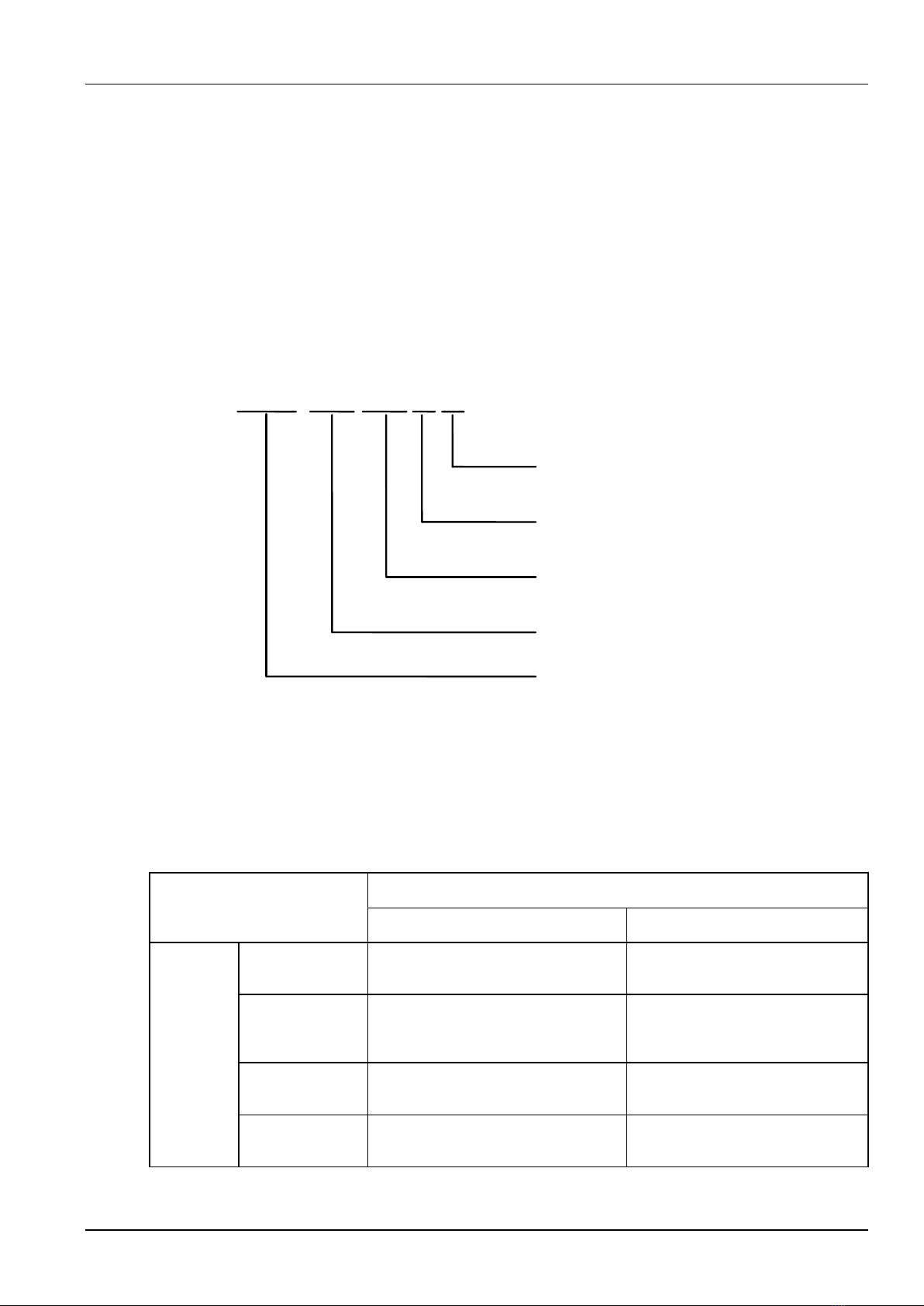
1.1 Model Description.......................................................................................................................................... 1
1.2 Technical Specifications................................................................................................................................. 1
1.3 External Dimensions and Gross Weight.......................................................................................................... 4
1.4 System Components and Configuration.......................................................................................................... 5
1.4.1 System Components........................................................................................................................... 5
1.4.2 Configuration...................................................................................................................................... 6
1.5 System Features.......................................................................................................................................... 9
Chapter 2 Installation and Cabling...........................................................................................................................12
2.1 Installation Requirements..............................................................................................................................12
2.2 Transportation Precautions ...........................................................................................................................12
2.3 Power Supply Specifications .........................................................................................................................13
2.4 Open-Package Inspection.............................................................................................................................14
2.5 Preparing the Cable Bundle...........................................................................................................................14
2.5.1 Packing List for the Cable Bundle Component Box..............................................................................14
2.5.2 Cable Bundle Preparation Description.................................................................................................15
2.6 Electric Connections .....................................................................................................................................16
2.6.1 Welder Output Cables........................................................................................................................17
2.6.2 Connecting the Gas Cylinder..............................................................................................................18
2.6.3 Connecting the Wire Feeder...............................................................................................................19
2.6.4 Connecting the Welding Torch............................................................................................................20
2.6.5 Connecting the Welding Power Cable (Grounding Cable) on the Workpiece Side.................................21
2.6.6 Connecting the Power Cable on the Power Input Side.........................................................................21
2.7 Welding Preparation......................................................................................................................................22
2.7.1 Safety Measures................................................................................................................................22
2.7.2 Installing the Welding Wire.................................................................................................................23
2.7.3 Turning on the Power Switch..............................................................................................................23
2.7.4 Adjusting the Gas Flow.......................................................................................................................24
2.7.5 Wire Inching.......................................................................................................................................24
2.7.6 Welding Conditions............................................................................................................................25
2.8 Post-welding Tasks.......................................................................................................................................30
Chapter 3 Welder Operation Description .................................................................................................................31
3.1 Welder Control Panel Structure.....................................................................................................................31
3.1.1 Front Control Panel............................................................................................................................31
3.1.2 Remote Control Box of the Wire Feeder..............................................................................................33
3.2 Buttons and Knobs........................................................................................................................................33
3.3 Screens and LED Indicators..........................................................................................................................34
3.4 Control Panel Functions................................................................................................................................35
3.4.1 Gas Shielded Arc Welding..................................................................................................................35
3.4.2 Spot Welding .....................................................................................................................................35
3.4.3 Welding Without Ending Arc...............................................................................................................37

3.4.4 Welding with Ending Arc.....................................................................................................................38
3.4.5 Welding with Repeated Ending Arc.....................................................................................................40
3.4.6 Synergic/Manual................................................................................................................................41
3.4.7 Arc Dynamic ......................................................................................................................................42
3.4.8 Detect Gas.........................................................................................................................................43
3.4.9 Wire Inching.......................................................................................................................................44
3.4.10 SAVE and LOAD..............................................................................................................................45
3.4.11 Lock.................................................................................................................................................47
3.4.12 Internal Menu...................................................................................................................................56
3.4.13 Welder Network Monitors .................................................................................................................57
3.5 Welding Electrode.........................................................................................................................................57
3.6 Intelligent Function Description......................................................................................................................57
3.6.1 Energy Conservation Function of the Fan............................................................................................57
3.6.2 Safety Protection Function for the Welding Torch................................................................................58
3.6.3 Slow Wire Inching ..............................................................................................................................58
3.6.4 Connecting a Robot............................................................................................................................58
3.7 Restoring Factory Settings............................................................................................................................62
Chapter 4 Maintenance.............................................................................................................................................63
4.1 Daily Inspection ............................................................................................................................................63
4.2 Regularly Inspection......................................................................................................................................64
4.3 Troubleshooting............................................................................................................................................66
4.3.1 Welder Fault Indicator ........................................................................................................................66
4.3.2 Welder Error Codes and Solutions......................................................................................................66
4.3.3 Rectifying Welder Faults and Welding Process Issues.........................................................................69
4.4 After-Sale Service.........................................................................................................................................70
Appendix I Technical Specifications........................................................................................................................71
Appendix II Electric Connections of Ehave CM250/350...........................................................................................73
Appendix III Electric Connections of Ehave CM500/500H........................................................................................74
Appendix IV Components.........................................................................................................................................75
Appendix V Detailed Component List ......................................................................................................................76

Chapter 1 Product Overview 1
Ehave Series Full Digital IGBT CO2/MAG/MMA Multifunctional Inverter Welder User Manual
Chapter 1 Product Overview
This chapter describes the model, appearance, dimensions, system components, system
configuration, technical specifications, and system features of the Ehave full digital heavy duty
IGBT CO2/MAG/MMA carrier intelligent multifunctional inverter welder.
1.1 Model Description
Figure 1-1 describes the welder model code format.
500: nominal current 500A
350: nominal current 350A
250: nominal current 250A
Ehave
500
CM
DR: digital robot
100% duty cycle
Welder series
H
CO2/MAG
T
AR: analog robot
T: customized
Figure 1-1 Model description
1.2 Technical Specifications
Table 1-1 describes the welder technical specifications.
Table 1-1 Technical specifications
Item
Description
Ehave CM250/350
Ehave CM500/500H
Input
Rated
voltage/frequency
Three-phase without neutral line, 380 V
50 Hz
Three-phase without neutral line,
380 V 50 Hz
Working voltage
range
Voltage: 285 V - 475 V; voltage
unbalance rate: < ±5%; frequency: 30
–80 Hz
Voltage: 285 V - 475 V; voltage
unbalance rate: < ±5%; frequency:
30 –80 Hz
Static tolerant
input voltage
Phase-to-phase voltage 520 V AC
Rated input power
factor
0.94
0.93

2Chapter 1 Product Overview
Ehave Series Full Digital IGBT CO2/MAG/MMA Multifunctional Inverter Welder User Manual
Item
Description
Ehave CM250/350
Ehave CM500/500H
Output
Rated open circuit
voltage
63.7 V
73.3 V(Ehave CM500)/75 V(Ehave
CM500H)
Rated output
current/voltage for
gas shielded
welding
30 A/15.5 V - (250) 350 A/(26.5) 31.5 V
30 A/15.5 V –500 A/39 V
Rated output
current/voltage for
manual welding
30 A/21.2 V - (250) 350 A/(30) 34 V
30 A/21.2 V –500 A/40 V
Rated duty cycle
350 (250) A@ 60% @ 40°C / 271 (193)
A@ 100% @ 40°C
350 (250) A@ 100% @ 25°C
Ehave CM500:
500 A@ 60% @ 40°C / 390 A@
100% @ 40°C
500 A@ 100% @ 25°C
Ehave CM500H:
500 A@ 100% @ 40°C
Change rate of
rated output
voltage
< ±5% (cold and hot states; 10% input
voltage fluctuation)
< ±5% (cold and hot states; 10%
input voltage fluctuation)
Line regulation
5%
5%
Output
characteristics
CV/CC
CV/CC
Output voltage
range
Adjustment range: 12 - (34) 38 V
Adjustment range: 12 –45 V
Output current
range
Adjustment range:
CO2/MAG: 30 - (300) 400A
MMA: 30 - (300) 400A
Instant short-circuit peak current: >
550 A
Adjustment range:
CO2/MAG: 30 –500 A
MMA: 30 –500 A
Instant short-circuit peak current:
> 550A
Adjustment range
of ending arc
voltage
Adjustment range: 12 - (34) 38 V;
step: 0.1 V
Adjustment range: 12 –45 V; step:
0.1 V
Adjustment range
of ending arc
current
Adjustment range: 30 - (300) 400 A;
step: 1 A
Adjustment range: 30 –500 A;
step: 1 A
Total positive and
negative output
cable length
Rated input; 15m/35mm2; (250) 350 A
60% normal operation/(193) 271 A
100% normal operation
Ehave CM500: rated input;
30m/50mm2; 500 A 60% normal
operation/ 390 A 100% normal
operation
Ehave CM500H: rated input;
30m/50mm2; 500 A 100% normal
operation
Main control
functions
LED screen
Sets welding voltage and current
values, and displays welding voltage
and current values and error codes.
Sets welding voltage and current
values, and displays welding
voltage and current values and
error codes.

Chapter 1 Product Overview 3
Ehave Series Full Digital IGBT CO2/MAG/MMA Multifunctional Inverter Welder User Manual
Item
Description
Ehave CM250/350
Ehave CM500/500H
Gas type
CO2; MAG
CO2; MAG
Wire type
Solid wire, flux-cored wire, and
electrode
Solid wire, flux-cored wire, and
electrode
Output control
Synergic/Manual
Synergic/Manual
Wire diameter
0.8; 1.0; 1.2
1.0; 1.2; 1.6
Welding control
Welding with ending arc
Welding without ending arc
Spot welding
Welding with repeated ending arc
Welding with ending arc
Welding without ending arc
Spot welding
Welding with repeated ending arc
Gas detection
Checks before welding whether a
shielding gas is used.
Checks before welding whether a
shielding gas is used.
Wire inching
Inches wire before welding.
Current and
voltage setup
In synergic mode, the current ranges
from 30 A to (300) 400 A and the
voltage knob is used to finely tune the
voltage within the range of ±9 V.
In manual mode, the current and
voltage are set independently, with
the current ranging from 30 A - (300)
400 A and the voltage ranging from 12
V - (34) 38 V.
In synergic mode, the current
ranges from 30 A to 500A and the
voltage knob is used to finely tune
the voltage within the range of
±9 V.
In manual mode, the current and
voltage are set independently, with
the current ranging from 30 A –500
A and the voltage ranging from 12
V - 45 V.
Arc dynamic
The knob on the control panel can be
used to set the value within the range
of -9 to +9, where -9 indicates the
softest arc and +9 indicates the
hardest arc.
The knob on the control panel can
be used to set the value within the
range of -9 to +9, where -9
indicates the softest arc and +9
indicates the hardest arc.
Spot welding time
In spot welding mode, the spot
welding time can be set on the control
panel within the range of 0.1 s -
10.0 s.
In spot welding mode, the spot
welding time can be set on the
control panel within the range of
0.1 s - 10.0 s.
Ending arc voltage
The voltage can be set using the knob
on the control panel within the range
of 12 V - (34) 38 V.
The voltage can be set using the
knob on the control panel within the
range of 12 V –45 V.
Ending arc current
The current can be set using the knob
on the control panel within the range
of 30 A - (300) 400 A.
The current can be set using the
knob on the control panel within the
range of 30 A –500 A.
Current setup for
manual welding
The current can be set using the knob
on the control panel within the range
of 30 A - (300) 400 A.
The current can be set using the
knob on the control panel within the
range of 30 A - 500A.
ENTER ,
LOAD , and
SAVE
buttons
They are used to confirm, save, load,
and lock welding parameters.
They are used to confirm, save,
load, and lock welding parameters.

4Chapter 1 Product Overview
Ehave Series Full Digital IGBT CO2/MAG/MMA Multifunctional Inverter Welder User Manual
Item
Description
Ehave CM250/350
Ehave CM500/500H
Protection function
Phase loss protection
Phase unbalance protection
Input overvoltage protection
Input undervoltage protection
Output overvoltage protection
Overheat protection
Overcurrent protection
Overload protection
Phase loss protection
Phase unbalance protection
Input overvoltage protection
Input undervoltage protection
Output overvoltage protection
Overheat protection
Overcurrent protection
Overload protection
Environment
Application site
The content of dust, acid, and corrosive
gas or substance in the surrounding
atmosphere must not exceed the
normal level (except those generated
during welding).
The content of dust, acid, and
corrosive gas or object in the
surrounding atmosphere must not
exceed the normal level (except
those generated during welding).
Altitude
≤2000m
≤2000m
Ambient
temperature
-10°C - +40°C (Perform derating when
the ambient temperature ranges
between 40°C and 50°C.)
-10°C - +40°C (Perform derating
when the ambient temperature
ranges between 40°C and 50°C.)
Humidity
< 95% RH without condensation
Vibration
< 200 Hz; < 1.0 m2/s3
Storage
temperature
-40°C - +70°C
-40°C - +70°C
Structure
Protection class
IP23S
IP23S
Cooling mode
Forced air cooling with fan control
Efficiency
Rated: 87%
Rated: 87%
Insulation class
H
H
Note: The preceding values in parentheses are dedicated to Ehave CM250. Ehave CM350AR and Ehave CM500AR
have the same specifications as Ehave CM350 and Ehave CM500 respectively.
1.3 External Dimensions and Gross Weight
Figure 1-2 shows the dimensions of the welder. Table 1-2 lists the gross weights of the welder
and its accessories.
Table 1-2 Gross weights of the welder and its accessories
Component
Gross Weight
Ehave CM250/350
Ehave CM500
Ehave CM500H
Welder
49 kg
52 kg
55 kg
Wire feeder
10 kg
10 kg
10 kg
Welding torch
3 kg
3.5 kg
3.5 kg

Chapter 1 Product Overview 5
Ehave Series Full Digital IGBT CO2/MAG/MMA Multifunctional Inverter Welder User Manual
Front view Side view Rear view
Figure 1-2 Welder dimensions (unit: mm)
1.4 System Components and Configuration
1.4.1 System Components
Figure 1-3 shows the components of the welding system.
Gas flow meter
Gas tube
Shielding
gas
Wire feeder
Welding power cable
on the wire feeder side
Control power cable on
the wire feeder side
Welding power
cable on the
workpiece side
Workpiece
Figure 1-3 System components

6Chapter 1 Product Overview
Ehave Series Full Digital IGBT CO2/MAG/MMA Multifunctional Inverter Welder User Manual
Figure 1-4 shows the structure of the welder.
4
1
2
3
5
7
6
13
12
98
11 10
Figure 1-4 Welder structure
SN
Name
Function
1
Input connector
Connects to the AC power supply.
2
Power cable clip
Fastens the AC power input cable.
3
M6 grounding stub
Connects to the grounding cable.
4
Fuse holder of the electrically-heated
gas regulator
Provide an 8 A fuse tube capacity.
5
Socket of the electrically-heated gas
regulator
Provides a 36 V AC power supply for the electrically-heated
gas regulator.
6
Communication connector
Facilitates communication with a computer.
7
Power switch
Connects or disconnects the AC power supply.
8
Negative output terminal
Connects to the welding material power cable.
9
Positive output terminal
Connects to the wire feeder power cable.
10
7-core aviation jack
Connects to the wire feeder control cable.
11
Fuse holder of the wire feeder
Provide an 8 A fuse tube capacity.
12
Parameter adjustment knob
Adjusts welding parameters. For details, see the operation
description.
13
Control panel
Adjusts the welding mode. For details, see the operation
description.
1.4.2 Configuration
Table 1-3, Table 1-4, and Table 1-5 show the configuration lists of welders.

Chapter 1 Product Overview 7
Ehave Series Full Digital IGBT CO2/MAG/MMA Multifunctional Inverter Welder User Manual
Table 1-3 Ehave CM250/350 configuration list
Name
Specifications
Quantity
Remarks
250 A/350 A power
supply
Ehave CM250/350
1
Standard
Wire feeder compliant
with Japanese
standards
PML/
WF2-35GA-MC/WF2-35GA-MD
1
Standard
Welding torch
compliant with
Japanese standards
Ehave
CM250:KR-200/QTB-200A
Ehave
CM350:KR-350/QTB-350A
1
Either type of welding torch is provided.
By default, a welding torch compliant
with Japanese standards is provided.
Welding torch
compliant with
European standards
Ehave CM250:MB 24 KD/N24
Ehave CM350:MB 36 KD/N36
1
User manual
Ehave series welder user
manual
1
Standard
Hex key
/
1
Standard
Bundle of output
cables
3 m –30 m (optional)
1
Either type of cables is provided. By
default, the cable bundle component
box is provided.
Cable bundle
component box
/
1
Welding power cable
on the workpiece side
1.8 m
1
Standard
Electrically-heated
gas regulator
GH-257-36/394C-25L-36
1
Optional
Welder caster
/
4
Optional
Welder tractor
29140008
1
Optional
Wire feeder caster
/
4
Optional
European-style
adapter
ZK-HQ-C1-000
1
Optional
Table 1-4 EhaveCM500/500Hconfiguration list
Name
Specifications
Quantity
Remarks
500 A power supply
Ehave CM500/500H
1
Standard
Wire feeder compliant
with Japanese
standards
PML/WF2-50GA-MC/WF2-50GA
-MD
1
Standard
Welding torch
compliant with
Japanese standards
KR-500/QTB-500A
1
Either type of welding torch is
provided. By default, a welding torch
compliant with Japanese standards is
provided.
Welding torch
compliant with
European standards
MB 36 KD/N36
1

8Chapter 1 Product Overview
Ehave Series Full Digital IGBT CO2/MAG/MMA Multifunctional Inverter Welder User Manual
Name
Specifications
Quantity
Remarks
User manual
Ehave series welder user
manual
1
Standard
Hex key
/
1
Standard
Bundle of output
cables
3 m –50 m (optional)
1
Either type of cables is provided. By
default, the cable bundle component
box is provided.
Cable bundle
component box
/
1
Welding power cable
on the workpiece side
1.8 m
1
Standard
Electrically-heated
gas regulator
GH-257-36/394C-25L-36
1
Optional
Welder caster
/
4
Optional
Welder tractor
29140008
1
Optional
Wire feeder caster
/
4
Optional
European-style
adapter
ZK-HQ-C1-000
1
Optional
Table 1-5 Ehave CM350AR/500AR configuration list
Name
Specifications
Quantity
Remarks
350 A/500 A power
supply
Ehave CM350AR/500AR
1
Standard
Robotic wire feeder
/
1
Standard
User manual
Ehave series welder user
manual
1
Standard
Hex key
/
1
Standard
Bundle of output
cables
7 m (optional)
1
Either type of cables is provided. By
default, the cable bundle component
box is provided.
Analog
communication cable
3 m
1
Standard
Wire guide nozzle for
the robotic wire
feeder
1
Optional
Nut for the robotic wire
feeder
1
Optional

Chapter 1 Product Overview 9
Ehave Series Full Digital IGBT CO2/MAG/MMA Multifunctional Inverter Welder User Manual
Name
Specifications
Quantity
Remarks
Bottom plate for
installation of the robotic
wire feeder
WF1-50P_R-0iA
1
Optional
Bottom plate for
installation of the robotic
wire feeder
WF1-50P_M-10iA, M-20iA
1
Optional
Welding power cable
on the workpiece side
50 m2/1.8 m
1
Standard
Electrically-heated
gas regulator
GH-257-36/394C-25L-36
1
Optional
Welder caster
/
4
Optional
Welder tractor
29140008
1
Optional
You must prepare the following:
Shielding Gas
Prepare CO2or a mixed gas. (Refer to Section 2.7.6 "Welding Conditions".)
CO2: The purity must be at least 99.5% and the moisture must be less than 0.005%.
MAG: Ar (80%) and CO2 (20%)
Welding Wire
Refer to Section 2.7.6 "Welding Conditions."
1.5 System Features
Duty Cycle
Rated duty cycle refers to the percentage of the time when the welder generates the rated
output in the 10-minute unit time. The rated duty cycle of Ehave CM250/350/350AR/500/500AR
is 60%. See Figure 1-5, which shows the duty cycle of Ehave CM500 as an example. The rated
duty cycle of Ehave CM500H is 100%. See Figure 1-6. The duty cycle of Ehave CM250 is
100% with the load lighter than 193A. The duty cycle of Ehave CM350/350AR is 100% with the
load lighter than 271 A. The duty cycle of Ehave CM500/500AR is 100% with the load lighter
than 390 A.

10 Chapter 1 Product Overview
Ehave Series Full Digital IGBT CO2/MAG/MMA Multifunctional Inverter Welder User Manual
Figure 1-5 Schematic diagram of the duty cycle of Ehave CM500
Figure 1-6 Schematic diagram of the duty cycle of Ehave CM500H
If the welder exceeds its rated duty cycle for a long time, the welder will become overheated,
resulting in aging or even damages of the welder.
If this welder is used along with other parts such as welding torches, the lowest duty cycle of the
parts must be applied to the entire set of device.
100%
60%
30
350
Current (A)
Current range used
500
390
100%
60%
30
270
350
Current (A)
Current range used
500

Chapter 1 Product Overview 11
Ehave Series Full Digital IGBT CO2/MAG/MMA Multifunctional Inverter Welder User Manual
Static and External Characteristics
The welder in CO2/MAG mode uses a constant–voltage welding power source and its
characteristics are shown in Figure 1-7. The welder in electrode mode uses constant-current
welding power source and its characteristics are shown in Figure 1-8.
Note
Ehave CM500/500H is used as an example.
0
10
20
30
40
50
60
70
80
0100 200 300 400 500 600
Figure 1-7 Schematic diagram of the constant–voltage welding power source (39 V)
0
10
20
30
40
50
60
70
80
050 100 150 200
Figure 1-8 Schematic diagram of the constant-current welding power source (150 A)

12 Chapter 2 Installation and Cabling
Ehave Series Full Digital IGBT CO2/MAG/MMA Multifunctional Inverter Welder User Manual
Chapter 2 Installation and Cabling
This chapter describes the welder installation requirements, installation procedure, and
precautions.
2.1 Installation Requirements
Environment Requirements
Pay attention to the following when selecting the installation environment:
The installation site must have good ventilation and vibration must be less than 5.9 m/s2 (0.6g).
Do not install it at a site with lots of dust or metal dust.
Do not install it at a site with corrosive or explosive gas.
The ambient temperature must range from -10°C to +40°C . When the temperature exceeds
40°C , forced external cooling or temperature derating is required.
The humidity must be lower than 95% without condensation.
When necessary, use windbreak at the welding site to prevent wind from affecting the welding
quality.
If you have special installation requirements, perform prior consultation and confirmation.
Installation Space Requirements
The welder must be at least 20 cm away from walls. If there are multiple welders, they must be
at least 30 cm away from each other. You are recommended to reserve space for the welders
as specified in Table 2-1.
Table 2-1 Space required for welder installation
Front
Top
Left
Right
Back
Space
required
≥20 cm
≥10 cm
≥20 cm
≥20 cm
≥20 cm
2.2 Transportation Precautions
1. Before moving the welder, cut off the input power of the distribution box.
2. When using a crane to move the welder, make sure that the hoist ring has been tightened
and the housing and cover plates of the welder have been installed.
3. If a crane is required to move the welder, use hoist rings and two lifting belts, and the
included angle of each lifting belt and the vertical direction must be less than 15 degrees.
See Figure 2-1.
This manual suits for next models
2
Table of contents
Other IGBT Welding System manuals