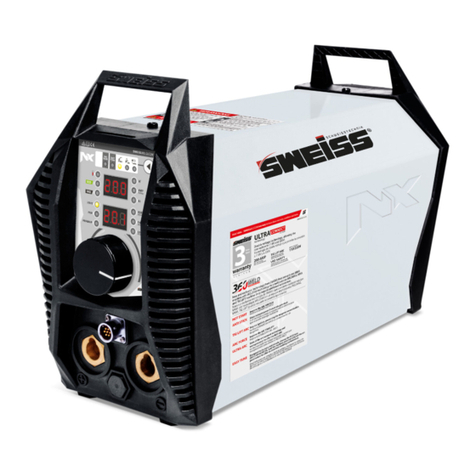
IGBT ARC Series User manual

1
TABLE OF CONTENTS
1. SAFETY..................................................................................................................2
2. GENERAL DESCRIPTION................................................................……………...3
3. MAIN PARAMETERS........................................................................……………...4
4. ELECTRIC BLOCK DIAGRAM...............................................................................5
5. OPERATION CONTROLAND DESCRIPTION......................................................6
6. INSTALLATION DEBUGGING AND OPERATION.................................................6
7. CAUTION...............................................................................................................7
8. MAINTENANCE.....................................................................................................8
9. TROUBLESHOOTING............................................................................................
9
DECLARATION OF CONFORMITY
Hereby we declare that these machines are produced based on relative
Chinese and international standards and they conform to the international safety
standard IEC974. The design and technology adopted in these machines are under
patent protection.
Please read and understand this manual carefully before the installation and
operation of these machines.
1. The contents of this manual may be revised without prior notice and without
obligation.
2. Although carefully checked, there may still be some inaccuracies in this
manual. Please consult us if any.
3. This manual is issued in Oct 2009.

2
Professional training is needed before operating the machine.
⚫Use labor protection welding supplies authorized by national
security supervision department.
⚫The operator must be qualified personnel with a valid "metal
welding (OFC) operations" operation certificate.
⚫Cut off power before maintenance or repair.
Electric shock—may lead to serious injury or even death.
⚫Install earth device according to the application criteria.
⚫Never touch the live parts when skin bared or wearing wet
gloves/clothes.
⚫Make sure that you are insulated from the ground and
workpiece.
⚫Make sure that your working position is safe.
Smoke& gas—may be harmful to health.
⚫Keep the head away from smoke and gas to avoid inhalation
of exhaust gas from welding.
⚫Keep the working environment in good ventilation with exhaust
or ventilation equipment when welding.
Arc radiation—may damage eyes or burn skin.
⚫Wear suitable welding masks and protective clothing to protect
your eyes and body.
⚫Use suitable masks or screens to protect spectators from
harm.
Improper operation may cause fire or explosion.
⚫Welding sparks may result in a fire, so please make sure no
combustible materials nearby and pay attention to fire hazard.
⚫Have a fire extinguisher nearby, and have a trained person to
use it.
⚫Airtight container welding is forbidden
⚫Do not use these machines for pipe thawing.
1. SAFETY
Welding is dangerous, and may cause damage to you and others, so take good
protection when welding. For details, please refer to the operator safety guidelines in
conformity with the accident prevention requirements of the manufacturer.

3
Hot workpiece may cause severe scalding.
⚫Do not contact hot workpiece with bare hands.
⚫Cooling is needed during continuous use of the welding torch.
Magnetic fields affect cardiac pacemaker.
⚫Pacemaker users should be away from the welding spot
before medical consultation.
Moving parts may lead to personal injury.
⚫Keep yourself away from moving parts such as fan.
⚫All doors, panels, covers and other protective devices should
be closed during operation.
Please seek professional help when encountering machine
failure.
⚫Consult the relevant contents of this manual If you encounter
any difficulties in installation and operation.
⚫Contact the service center of your supplier to seek
professional help if you still can not fully understand after
reading the manual or still can not solve the problem
according to the manual.
2. GENERAL DESCRIPTION
➢Advanced IGBT inverter technology
◆High inverter frequency greatly reduces the volume and weight of the welder.
◆Great reduction in magnetic and resistance loss obviously enhances the welding
efficiency and energy saving effect.
◆Switching frequency is beyond audiorange, which almost eliminates noise pollution.
➢Leading control mode
◆Advanced control technology meets various welding applications and greatly improves
the welding performance.
◆It can be widely used in acid and basic electrode welding.
◆Easy arc starting, less spatter, stable current and good shaping.
➢Features of ARC series
◆Efficiency, energy saving, portable, stable arc, high no-load voltage, and with good
compensation of arc force, are able to meet various welding requirements in field work.
➢Beautiful appearance for enclosure design
◆Streamline design of the front panel and back panel makes the overall shape more
attractive.
◆Front panel and back panel are made of high-intensity engineering plastics, which

4
effectively ensures reliable performance of the machines in severe conditions.
◆Excellent insulation.
3. MAIN PARAMETERS
MODEL
ARC120
ARC140
ARC160
ARC180
MODEL ARC180
Rated input
voltage (V)
AC230V±15% 50/60HZ
AC230V±15% 50/60HZ
Rated input
power (KVA)
5
6
7.11
8
6
7.11
Rated input power
(KVA)
8
6
7.11
Rated input
current (A)
22
26
31
35
26
31
Rated input current (A)
35
26
31
Rated output
120A/24.8V
140A/25.6V
160A/26.5V
180A/27.2V
140A/25.6V
160A/26.5V
Rated output
180A/27.2V
140A/25.6V
160A/26.5V
Welding current
range (A)
10~120A
10~140A
10~160A
10~180A
10~140A
10~160A
Welding current range
(A)
10~180A
10~140A
10~160A
No-load voltage
(V)
72
72
72
72
67
No-load voltage (V)
76
67
67
Rated duty cycle
25%@40℃
30%@40℃
30%@40℃
30%@40℃
30%@40℃
30%@40℃
Rated duty cycle
30%@40℃
30%@40℃
30%@40℃
Efficiency (%)
85
85
85
85
85
85
Efficiency (%)
85
85
85
Power factor
0.70
0.70
0.70
0.72
0.70
0.70
Power factor
0.72
0.70
0.70
Protection class
IP21S
IP21S
IP21S
IP21S
IP21S
IP21S
Protection class
IP21S
IP21S
IP21S
Insulation class
F
F
F
F
F
F
Insulation class
F
F
F
Size (mm)
268×120×198
268×120×198
313×145×220
313×145×220
Weight (Kg)
4.1
4.7
5.2
5.8
Weight (Kg)
5.8kg
Rated input
voltage (V)
AC110%±10% 50/60Hz
50/60Hz
Rated input
power (KVA)
5
6
7.11
8
Rated input
current (A)
22
26
31
35
Rated output
110A/24.4
110A/24.4
110A/24.4
110A/24.4
Welding current
range (A)
10-110A
10-110A
10-110A
10-110A
No-load voltage
(V)
72
72
72
72
Rated duty cycle
25%@40℃
30%@40℃
30%@40℃
30%@40℃
30%@40℃
30%@40℃
Rated duty cycle
30%@40℃
30%@40℃
30%@40℃
Efficiency (%)
85
85
85
85
Power factor
0.72
0.72
0.72
0.72
Protection class
IP21S
IP21S
IP21S
IP21S
Insulation class
F
F
F
F
Size (mm)
268x120x198
268x120x198
315x145x220
315x145x220
Weight (Kg)
4.1
4.7
5.2
5.8

5
4. ELECTRIC BLOCK DIAGRAM
5. OPERATION CONTROL AND DESCRIPTION
●Front control panel (see Figure 1)
(1) "+" output terminal: To connect the electrode holder.
(2) "-" output terminal: To connect the work clamp.
(3) Welding current knob: To adjust the output current.
(4) Power LED: To indicate the power. Power LED on indicates that the power switch of the
machine is on.
(5) Overheating LED: To indicate overheating. Overheating LED on indicates that the
temperature inside the machine is too high and the machine is under overheating protection
status.
(6) MMA/TIG switch: To toggle between MMAand TIG.
●Back control panel (see Figure 2)
(7) Power input: Power input cable.
(8) Power switch: Power ON/OFF switch.
(9) Fan

6
Figure 1 Figure 2
6. INSTALLATION DEBUGGING AND OPERATION
Note: Please install the machine strictly according to the following steps.
Turn off the power supply switch before any electric connection operation.
The protection class of this machine is IP21S, so avoid using it in rain.
6.1 Installation method
(1) A primary power supply cable is available for this welding machine. Connect the power
supply cable to the rated input power.
(2) The primary cable should be tightly connected to the correct socket to avoid oxidization.
(3) Check whether the voltage value varies in acceptable range with a multi-meter.
(4) Insert the cable plug with electrode holder into the “+” socket on the front panel of the
welding machine, and tighten it clockwise.
(5) Insert the cable plug with work clamp into the “-” socket on the front panel of the welding
machine, and tighten it clockwise.
(6) Ground connection is needed for safety purpose.
The connection as mentioned above in 6.1(4) and 6.1(5) is DCEP connection. Operator
can choose DCEN connection according to workpiece and electrode application
requirement. Generally, DCEP connection is recommended for basic electrode, while no
special requirement for acid electrode.
6.2 Operation method
(1) After being installed according to the above method, and the power switch being
switched on, the machine is started with the power LED on and the fan working.
(2) Pay attention to the polarity when connecting. Phenomena such as unstable arc, spatter,
and electrode sticking could happen if improper mode is selected. Exchange the polarity
if necessary.
(3) When switching the MMA/TIG switch to MMA mode, normal welding can be carried out
under rated output current. When switching the MMA/TIG switch to TIG position and
using lift arc ignition, arc can be successfully started under rated arc ignition current, and
normal welding can be carried out under rated welding current.
(4) Select cable with larger cross-section to reduce the voltage drop if the secondary cables
(welding cable and earth cable) are long.

7
(5) Preset the welding current according to the type and size of the electrode, clip the
electrode and then welding can be carried out by short circuit arc starting. For welding
parameters, please refer to 6.3.
6.3 Welding parameters table (for reference only)
Electrode dia. (mm)
Recommended welding
current (A)
Recommended welding
voltage (V)
1.0
20~60
20.8~22.4
1.6
44~84
21.76~23.36
2.0
60~100
22.4~24.0
2.5
80~120
23.2~24.8
3.2
108~148
23.32~24.92
4.0
140~180
24.6~27.2
5.0
180~220
27.2~28.8
6.0
220~260
28.8~30.4
Note: This table is suitable for mild steel welding. For other materials, consult related
materials and welding process for reference.
7. CAUTION
1. Working Environment
(1) Welding should be carried out in dry environment with its humidity of 90% or less.
(2) The temperature of the working environment should be between -10℃to 40℃.
(3) Avoid welding in the open air unless sheltered from sunlight and rain. Keep it dry anytime
and do not place it on wet ground or in puddles.
(4) Avoid welding in dusty area or environment with corrosive chemical gas.
(5) Gas shielded arc welding should be operated in environment without strong airflow.
2. Safety Tips
Over-current/over-voltage/over-heating protection circuit is installed in this machine. If the
input voltage or the output current is too high or machine inside temperature over heating inside,
the machine will stop automatically. However, excessive use (e.g. too high voltage) of machine
may also damage machine, so please note:
2.1 Ventilation
High current passes when welding is carried out, thus natural ventilation can not satisfy the
machine's cooling requirement. Maintain good ventilation through the louvers of the machine. The
minimum distance between the machine and any other objects in or near the working area should
be 30cm. Good ventilation is of critical importance for the normal performance and lifespan of the
machine.
2.2 Welding operation is forbidden while the machine is overload. Remember to observe the
max load current at any moment (refer to the corresponding duty cycle). Make sure that the
welding current should not exceed the max load current. Overload could obviously shorten the
machine's lifespan, or even damage the machine.
2.3 Over-voltage is forbidden.
Regarding the power supply voltage range of the machine, please refer to “Main Parameters”

8
The following operation requires sufficient professional
knowledge on electric aspect and comprehensive safety
knowledge. Operators should be holders of valid qualification
certificates which can prove their skills and knowledge. Make
sure the input cable of the machine is cut off from the electricity
utility before uncovering the welding machine.
(1) Check periodically whether inner circuit
connection is ok (esp. plugs). Tighten the loose connection. If
there is oxidization, remove it with sandpaper and then
reconnect.
(2) Keep hands, hair and tools away from the moving
parts such as the fan to avoid personal injury or machine
damage.
(3) Clean the dust periodically with dry and clean
compressed air. If welding in environment with heavy smoke
and pollution, the machine should be cleaned daily. The
pressure of compressed air should be at a proper lever lest the
small parts inside the machine be damaged.
(4) Avoid rain, water and vapor infilter the machine. If
there is, dry it and check the insulation with a megger (including
that between the connections and that between the connection
and the case). Only when there is no abnormal phenomena can
welding be continued.
(5) Check periodically whether the insulation skin of all
cables are perfect. If there is any dilapidation, wrap it or replace
it.
(6) Put the machine into the original packing in dry
location if it is not to be used for a long time.
The following operation requires sufficient professional
knowledge on electric aspect and comprehensive safety
knowledge. Operators should be holders of valid qualification
certificates which can prove their skills and knowledge. Make
sure the input cable of the machine is cut off from the electricity
utility before uncovering the welding machine.
(1) Check periodically whether inner circuit
connection is ok (esp. plugs). Tighten the loose connection. If
there is oxidization, remove it with sandpaper and then
reconnect.
(2) Keep hands, hair and tools away from the moving
table. This machine is of automatic voltage compensation, which enables the maintaining of the
voltage range within the given range. In case that the input voltage exceeds the stipulated value, it
would possibly damage the components of the machine.
2.4Asudden halt may occur while the machine is of overload status. Under this circumstance,
it is unnecessary to restart the machine. Remain the built-in fan working to lower the temperature
inside the machine.
8. MAINTENANCE
(1) Check periodically whether inner circuit connection is in good condition (esp. plugs).
Tighten the loose connection. If there is oxidization, remove it with sandpaper and then
reconnect.
(2) Keep hands, hair and tools away from the moving parts such as the fan to avoid personal
injury or machine damage.
(3) Clean the dust periodically with dry and clean compressed air. If welding environment
with heavy smoke and pollution, the machine should be cleaned daily. The pressure of
compressed air should be at a proper level in order to avoid the small parts inside the
machine to be damaged.
(4) Avoid rain, water and vapor infilter the machine. If there is, dry it and check the insulation
with equipment (including that between the connections and that between the connection
and the enclosure). Only when there are no abnormal phenomena anymore, then the
machine can be used.
(5) Check periodically whether the insulation cover of all cables is in good condition. If there
is any dilapidation, rewrap it or replace it.
(6) Put the machine into the original packing in dry location if it is not to be used for a long
time.
9. TROUBLESHOOTING
Common Malfunction Analysis and Solution:
Malfunction Phenomena
Cause and Solution
Turn on the machine, the power LED is off,
(1) Check if the power switch is closed.

9
the fan doesn't work, and no welding output.
(2) No input power.
Turn on the machine, the fan works, but the
output current is unstable and can't be
controlled by potentiometer when welding.
(1) The current potentiometer fails. Replace it.
(2) Check if any loose contact exists inside the
machine. If any, reconnect.
Turn on the machine, the power LED is on,
the fan works, but no welding output.
(1) Check if any loose contact exists inside the
machine.
(2) Open circuit or loose contact occurs at the
joint of output terminal.
(3) The overheating LED is on.
a) The machine is under over-heating
protection status. It can recover
automatically after the welding machine
is cooled.
b) Check if the thermal switch is ok.
Replace it if damaged.
The electrode holder becomes very hot.
The rated current of the electrode holder is
smaller than its actual working current. Replace
it with a bigger rated current.
Excessive spatter in MMA welding.
The output polarity connection is incorrect.
Exchange the polarity.
We are still constantly improving this welder, therefore, some parts of this welder may
be changed in order to achieve the better quality, but the main functions and operations
will not be alternated and changed. Your understanding would be greatly appreciated.
This manual suits for next models
4
Table of contents
Other IGBT Welding System manuals
Popular Welding System manuals by other brands

Victor
Victor CUTMASTER 102 Service manual
SincoSald
SincoSald NOVAMIG 503 DP WP3-4R FEEDER G.R.3 instruction manual
Miller
Miller PipeWorx 400 owner's manual
NewArc
NewArc R7000 instruction manual

Lincoln Electric
Lincoln Electric RED-D-ARC LN-25 PRO EXTREME Operator's manual
Lincoln Electric
Lincoln Electric K2481-1 Operator's manual
Abicor Binzel
Abicor Binzel iROB 420 quick guide
Lincoln Electric
Lincoln Electric Making Fillet Welds Specification sheet

Lincoln Electric
Lincoln Electric CLASSIC 300G 10659 Operator's manual

ESAB
ESAB Origo Mig 410 instruction manual

Migatronic
Migatronic Delta 200 DC HP PFC instruction manual
iWeld
iWeld DYNAMIG 560 user manual
