IGEBA EVO 35 User manual
EVO 35 - EVO 35 E
Справочное руководство
Instruction manual
Термомеханические аэрозольные генераторы

04/2010 1.0 3 72
:Summary ./Page
Restricted fields of application………… 4
Manufacturer and Distributor…………
…
5
Warranty………………………………… 6
Declaration of conformity……………… 7-8
Mode of operation……………………… 9
Notes on the instructional manual……
…
10
: Safety instructions – product liability…
…
11-14
Warning and safety notes……………
…
15 - 17
CE/
CE Marking/short manual……………… 18
EVO 35 Functional parts EVO 35………………
…
19
Safety Instructions……………………… 20 - 26
Prepare unit ready for use……………
…
27 - 33
Starting the unit…………………………
…
34 - 35
Stopping the unit………………………
…
35 - 36
Cleaning the unit………………………
…
36 - 39
/ Cleaning the mixing chamber/mixing
pipe…………………………………….. 40 - 42
Maintenance of the pump……………… 42
Fault finding……………………………
…
43 - 52
EVO 35 E Functional parts EVO 35 E……………
…
53 - 54
Operation with Emergency-Cut-Off-
device………………………………….. 55
A
djustment of the Bowden cable……
…
56
Basic setting Emergency-Cut-Off-
device………………………………….. 57 - 58
Technical data…………………………
…
59
Manufafcturing programm……………
…
61
Spare parts list…………………………
…
62-72
04/2010 1.0 19 72
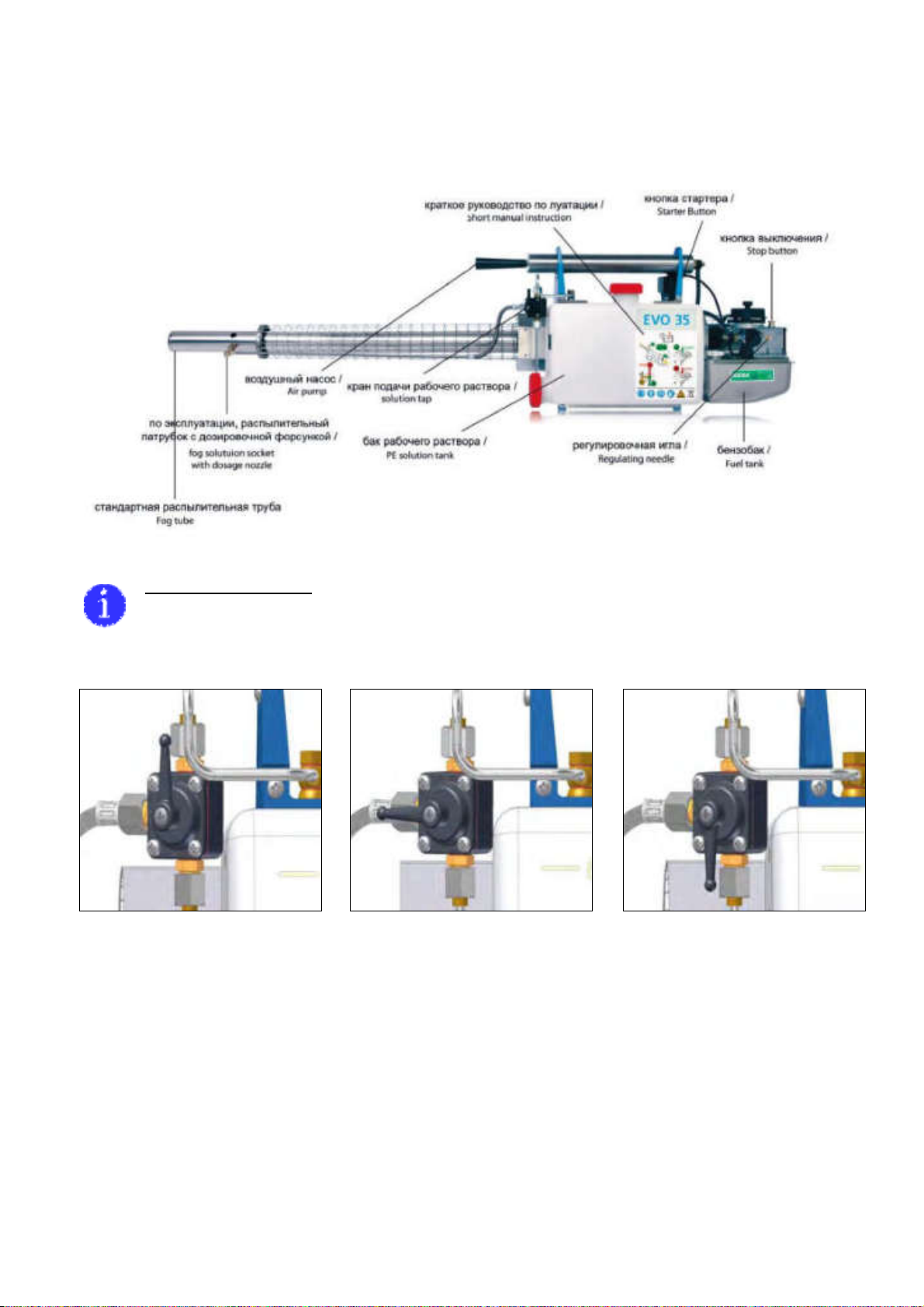
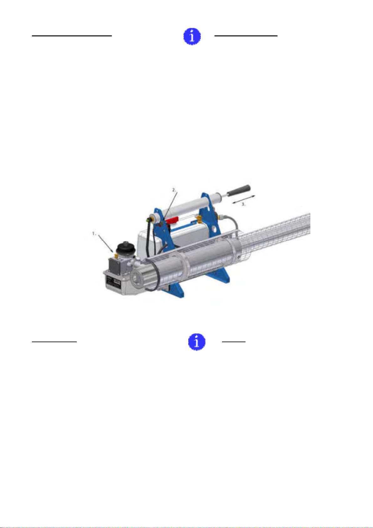
EVO 35
The important functional parts of EVO 35 at a glance
/ Notice:
Solution tap positions
– Closed - Ventilation – Open
04/2010 1.0 22 72
6.
( ..).
6. It is forbidden to fog in rooms with finest
combustible dust particles (e.g. grain silo),
because danger of dust explosion.
7.
, ,
.
7. It is forbidden to fog in enclosed rooms
where open flames, candle lights, hot
engines or electrical appliances exist,
because of fire danger.
8.
,
.
,
.
,
.
.
.
,
.
8. When fogging in enclosed rooms, take
into account that fogging can lead to fire
and explosions if the concentration of fog
in a room exceeds a crucial value. This is
due to the combustible additives of such a
fog. Follow dosing recommendations,
particularly when fogging indoors. Do not
fog longer than necessary. Application of
formulations with combustible fractions
may lead to formation of an explosive
mixture. Make yourself familiar with the
dosage of combustible additives in
enclosed rooms. Calculate the maximum
quantity of combustible additive depending
on room size, nozzle size and fogging time,
before you start fogging into enclosed
rooms.
9.
.
9. It is not allowed to transport the unit in a
closed vehicle, as long as the unit is hot.
Wait until the unit has cooled down.
10. Э
.
10. Do not leave the working unit
unattended.

04/2010 1.0 27 72
1.
:
.
(. 1, . 9)
. W
(. 1, . 10)
.
1. Prepare unit ready for use:
Due to packing reasons, the fog tube is not
mounted on the unit. The standard fog tube
(illus. 1 pos.9) must be used for oil based
formulations. The fog tube type W (iIllus.1
pos.10) must be used for water based
formulations.
. 1
() - . 68
illus. 1
SP list page 68
!
W
–
.
W
10 %
( , «»)
.
Attention!
Never use the fog tube type W for oil
based formulations, there is fire danger.
When fogging with fog tube type W,
addition of 10% special carriers (e.g.
Nebol) is allowed in order to improve the
droplet spectrum.

04/2010 1.0 28 72
(. 2,
.11)
.
Fit the protective guard (illus. 2 pos.11) to
the end of the cooling jacket and tighten
clamp.
. 2
- . 68
illus. 2
SP list page 68
(.
3, . 9)
,
(. 3A, . 9)
.
Push fog tube (illus.3 pos.9) over the
resonator into the cooling jacket until the
hole is aligned (illus.3a pos.9) with the
screw neck to screw in the fog solution
socket.
. 3 / illus. 3
- . 68 / SP list page 68
рис. 3a / illus. 3a
СЗЧ - стр. 68 / SP list page 68

04/2010 1.0 29 72
(. 4).
(.
5). ,
(. 5).
Screw in the fog solution socket by hand
(illus. 4). Connect fog solution socket and
solution line via the dosage nozzle and
related copper gaskets (illus.5). When
tightening the dosage nozzle secure the
position of the fog solution socket with a
second flat spanner (illus.5).
. 4
- . 68
illus. 4
SP list page 68
. 5
- . 68
illus. 5
SP list page 68

04/2010 1.0 30 72
йки:
.
. (.
).
1,5 LR20
.
(. 6).
Inserting the batteries:
Remove the upper wing thumb screw
completely. It is sufficient to loosen the
lower thumb screw a few revolutions. You
can take off the battery cover now (see
note). Insert four batteries Type 1,5V LR20
with the positive pole forward inside the
unit. Mount the battery cover and tighten
thumb screws evenly by hand (illus. 6).
. 6
- . 64
illus. 6
SP list page 64
(. 7, .13)
.
.
Check ignition coil by pressing starter
button (illus. 7 pos. 13) a buzzing sound
must be easily audible.
. 7
- . 64
illus. 7
SP list page 64
04/2010 1.0 31 72
,
> 75.
е .
(. 8, . 2).
,
.
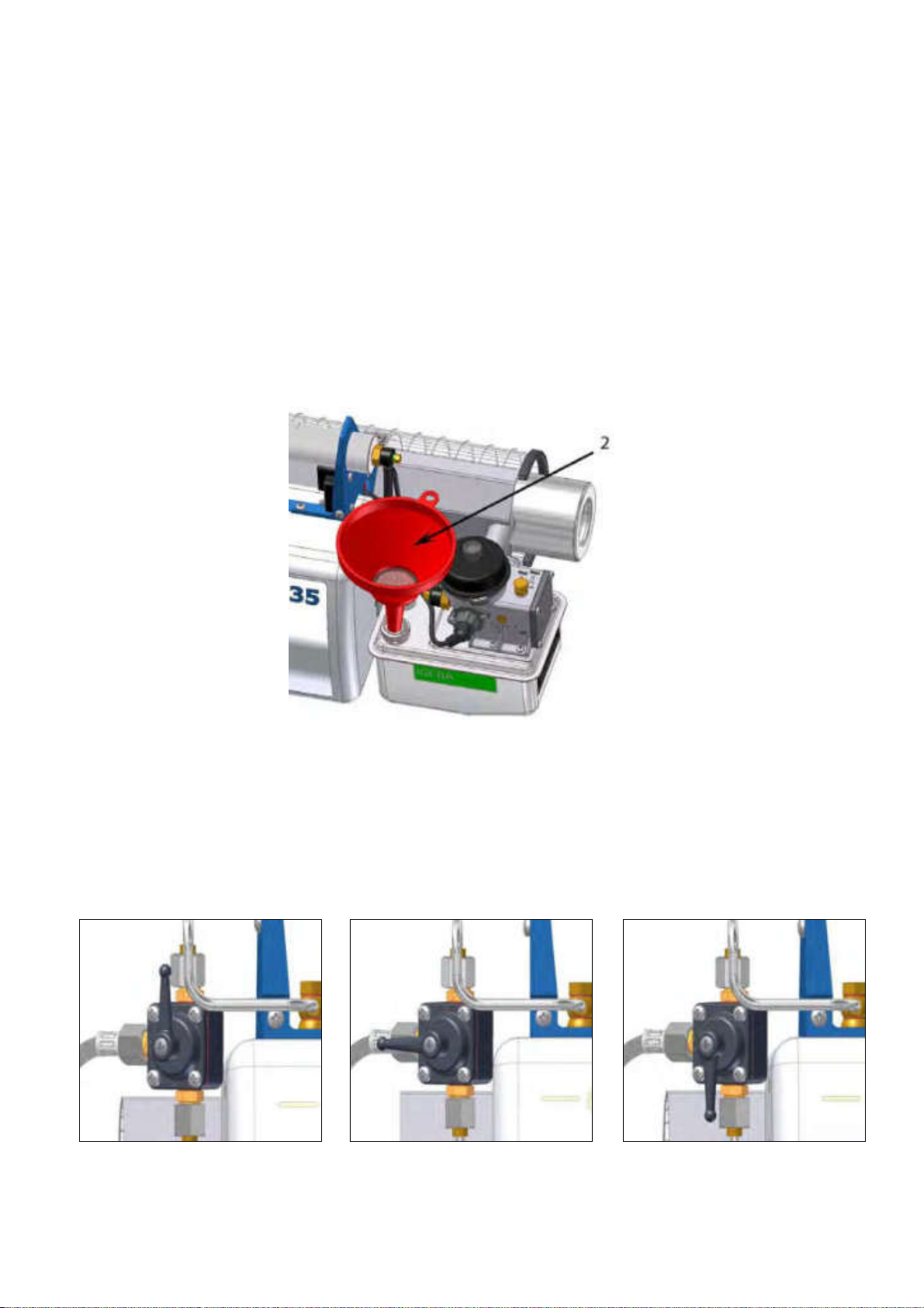
Fill petrol tank with petrol > 75 ROZ,
without any additives. There is no
advantage achieved in using higher grade
petrol. Please use the provided funnel with
strainer (illus. 8 pos. 2). After filling, tighten
petrol cap firmly by hand.
. 8
- . 71
illus. 8
SP list page 71
,
.
(. 9).
Make sure that solution tap is closed. Lever
points upwards (illus. 9).
. 9
- . 70
illus. 9
SP list page 70
– Closed - Ventilation – Open

04/2010 1.0 32 72
.
(. 10, . 1).
.
Fill solution tank. Always use the provided
solution funnel with filter (illus. 10 pos. 1).
Tighten tank cap firmly by hand.
. 10
- . 71
illus 10.
SP list page 71
Solution output through Dosage
Nozzles
EVO 35
1.2.
0.8.
EVO 35 is already equipped with a dosage
nozzle size of 1.2. A Nozzle with size 0.8 is
in the scope of supply.
EVO 35 W
1.0.
Another nozzle with size 1.0 is in the scope
of supply, when you order
EVO-W 35.
()
:
›0.8*1.0* 1.2 1.4 1.6 2.0
/ ›10 15 20 30 35 42
*
EVO W 35.
Water has been used to determine the
following outputs (rough values):
Nozzle size ›0.8*1.0* 1.2 1.4 1.6 2.0
Liter/hour ›10 15 20 30 35 42
* solely use these dosage nozzles for
EVO W 35.

04/2010 1.0 33 72
20%.
. Э
.
W
1.0.
The output (liter/hour) differs up to 20%
due to the different chemical and physical
properties of the formulations. We advise
you to do your own metering of the output
under prevailing conditions. This refers
mainly to tropical countries.
When applying water based formulations
use a small dosage nozzle size max. 1.0
and assemble fog tube type W (109) for
water based formulations.
:
.
1000 3:
Caution:
Overdosage of agent in closed rooms my
lead to formation of an explosive mixture.
The dose of these combustible materials in
ready mixed fogging formulations must not
exceed the following maximum
concentrations per 1.000 cu. metres.
a) д: ) , :
3,0 2,5
2,5 /. 2,0
Э 2,0 2,0
Э 2,0 Petropal 2,0
2,0 Shell Risella 15 1,5
VK 2-spezial 2,0
a.) Special Carriers: b.) Fuels/White Oils:
Nebol 3,0 l Vegetable oils 2,5 l
Glyzerine 2,5 l Diesel-/Heating oil 2,0 l
Ekomist 2,0 l Kerosene 2,0 l
Ethylenglykole 2,0 l Petropal 2,0 l
Diethylenglykole 2,0 l Shell Risella 15 1,5 l
VK 2-spezial 2,0 l
,
,
.
, по
предварительным подсчетам
обрабатываемого .
Though these values may not correspond
with those given by the manufacturers and
may be higher than limits quoted in dosage
tables. We recommend to fill in only the
calculated (necessary) volume of agent for
the treated room.
04/2010 1.0 34 72
2. :
(. 11, . 1) .
( ) (. 11,
. 2).
, -
(. 11, . 3).
,
1–2
.
2. Starting the unit:
Pull stop button at the carburettor upwards
(illus. 11 pos.1).
Press starter button (for ignition) and keep
pressed (illus 11 pos.2).
Actuate air pump . Pump evenly, (illus. 11
pos.3) not fitfully.
When the first explosions are audible,
pump another 1–2 strokes. The unit should
run properly now. Release starter button.
. 11 illus. 11
:
, ..
,
.
. ,
1 .
(. . 12, .
35). После разогрева прибора,
„ON“ ().
Notice!
The air pump creates pressure for the
petrol supply. The lower the petrol in the
tank, the more pumping strokes are
necessary. Always start with a full tank if
possible. Bring the solution tap in position
“ON” (Fogging) after the warm-up period
(illus.12 page 35).

04/2010 1.0 35 72
. 12
- . 70
illus. 12
SP list page 70
– Closed - Ventilation – Open
!
,
, .
6,5- -
,
,
8-36 .
2 /, .. 1,2
36 .
Important!
Make sure that the amount of petrol is
sufficient for the intended period of fogging.
The content of the standard solution tank is
6,5 liter, which is fogged according to the
size of the dosage nozzle between 8 and
36 minutes. The unit runs about 36
minutes w ith a full fuel tank (1,2l).
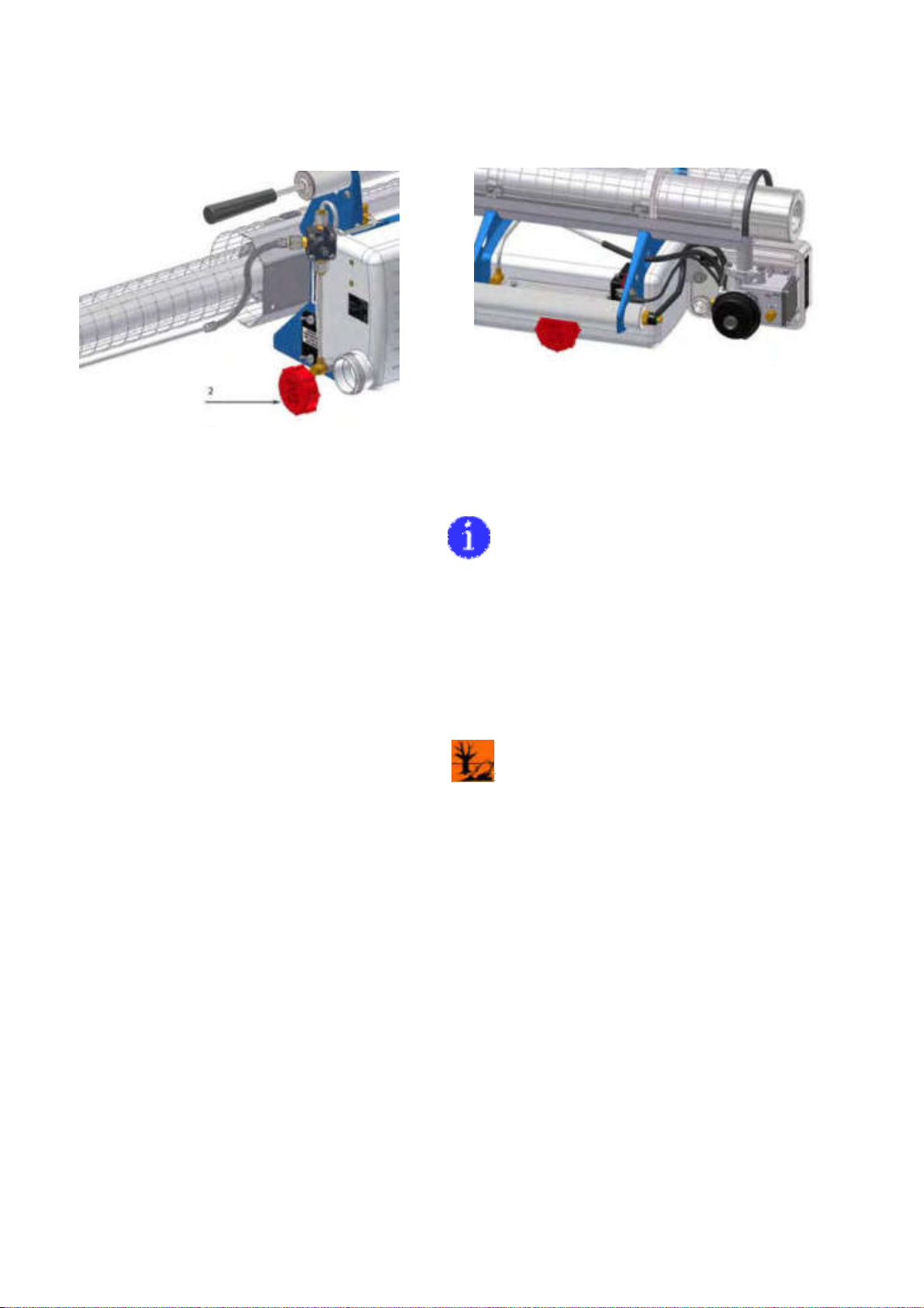
3. :
рабочего
,
.
„“
(. 13).
,
. З
(
,
- . 13).
,
«STOP». ,
.
3. Stopping the unit:
Turn lever of solution tap at first into
position VENTILATION. Lever is in
horizontal position. In position
VENTILATION air is ventilated through the
solution line and through the fog solution
socket (illus. 13).
Wait until fog is no longer visible.
Now turn lever of solution tap into position
closed (illus. 13).
Push stop button at the carburettor down
into position STOP. The unit stops and no
explosions are audible (illus. 11 page 34).
Actuate air pump about 3–4 times and
press simultaneously starter button.

04/2010 1.0 36 72
3–4 ,
.
ки а
(. 11, . 34).
,
.
!
.
Explosions of remaining gases might be
audible (illus. 11 page 34).
Release pressure from solution tank by
turning tank cap to the left.
Attention!
Do not tighten tank cap hard during
storage of the unit.
. 13
- . 70
illus. 13
SP list page 70
– Closed - Ventilation – Open
4. Ч :
,
коррозионноустойчивых ,
.
0,5
, ,
.
,
(. 14, . 2)
,
.
.
4. Cleaning the unit:
Although all solution carrying pipes are
made of rust proof material, the solution
line should be cleaned after the application
/ change of active substance. Pour a half
liter of water into the solution tank, shake
the unit and fog. If fogging is not possible,
unscrew fog solution socket and atomizer
nozzle, so that the water can flow through
solution line into a container. Water can
also flow out of the opening at the bottom
of the solution tank (illus.14 pos.2).
04/2010 1.0 37 72
. 14 illus 14.
- . 65 SP list page 65
. 14a illus. 14a.
При и
.
0,25
,
, (.
14a) .
.
.
By using dirty petrol cans or polluted
petrol, debris may be piled up inside the
petrol tank. This debris can be removed of
the tank by filling up a quarter liter of
gasoline. Shake the unit carefully and
decline the entire unit so that fuel together
with debris can flow out of the opening
(illus.14a.) of the fuel tank. Prepare an
appropriate container to collect the
solution. If necessary repeat the
procedure. The unit must be cooled-down
before cleaning.
04/2010 1.0 38 72
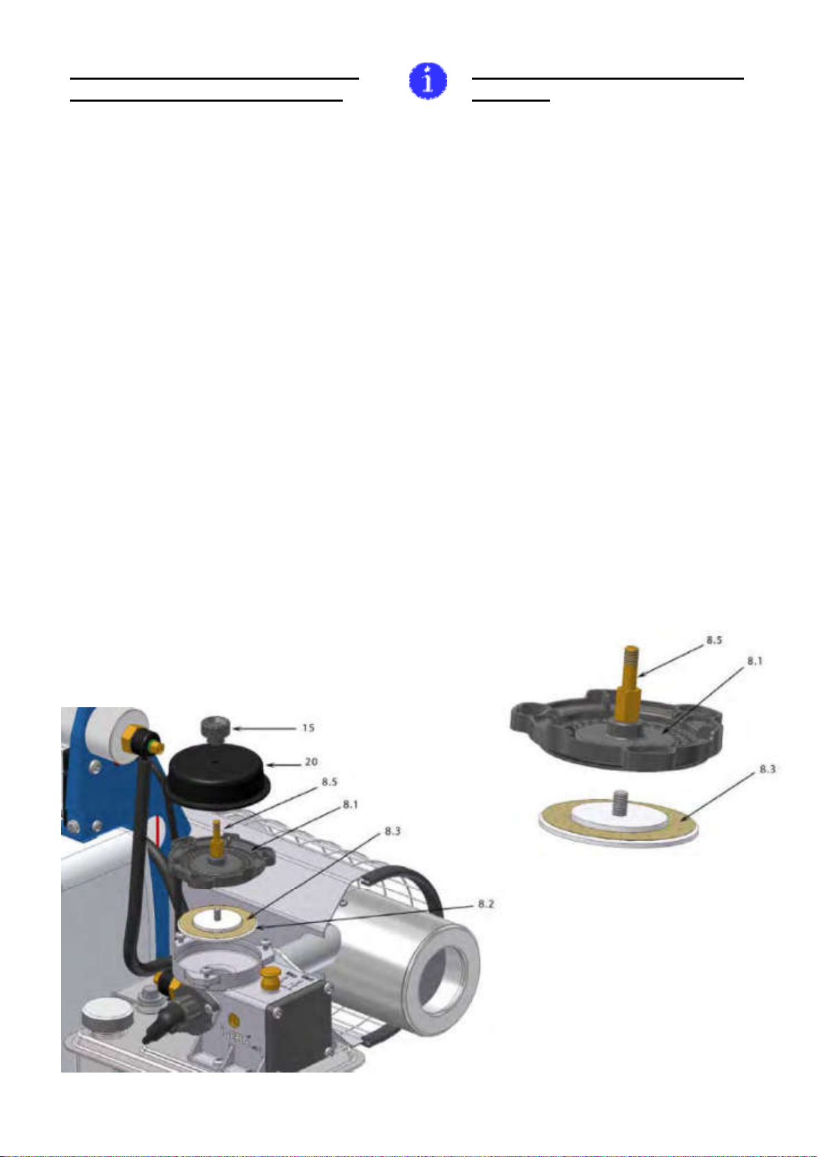
:
a)
)
(. 14, . 37);
)
)
(. 15, . 8.3),
( , ) .
.
(. 16, . 8.1)
(. 16, .
8.2).
.
We recommend before longer periods
of storage:
a.) Remove batteries from the unit and
store them at a safe and dry place.
b.) Remove solution from the solution tank
and clean as stated above. (illus. 14 page
37 ) Do not tighten tank cap hard.
c.) Clean the unit from the outside.
d.) Remove diaphragm of air intake valve
(illus.15 pos.8.3). Check for any damage.
A damaged diaphragm must be replaced.
Clean diaphragm (illus. 16 pos. 8.1), valve
plate (illus. 16 pos. 8.2) and spacer plate.
Clean with a tidy cloth and/or suitable
cleaning agent.
. 15
- . 69
illus. 15
SP list page 69
. 16 illus.16
- . 69 SP list page 69
04/2010 1.0 39 72
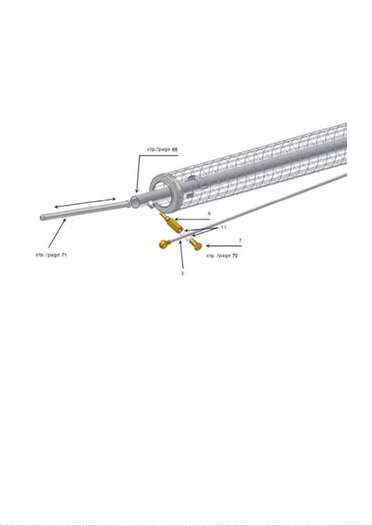
) ,
(. 17, . 3).
e.) Remove residues in resonator, fog -
solution socket and possibly fog tube with
pipe cleaning tool (illus.17, pos.3).
. 17
- . 68-70
illus. 17
SP list page 68-70

04/2010 1.0 40 72
5. Ч
a) отсоедините контактный наконечник от плунжера
(. 18,поз. 2).
5.Cleaning from the mixing chamber and
mixing pipe.
a.) Remove the plug from the swirl vane
(illus. 18 pos.2).
. 18
- . 69 illus. 18
SP list page 69
) (. 18
. 11) , плунжер
(.
19, . 21, . 41):
.
,
,
, .
.
b.) Release the fixing screws (illus.18
pos.11) a few revolutions until you can
remove the swirl vane with a short counter-
clockwise rotation (illus 19 pos.21 page 41).
Remove the O-Ring from the carburettor
housing. Please check the O-Ring, a
damaged O-Ring must be replaced.
Please lay the O-Ring aside during the
cleaning.

04/2010 1.0 41 72
. 19
- . 69
illus. 19
SP list page 69
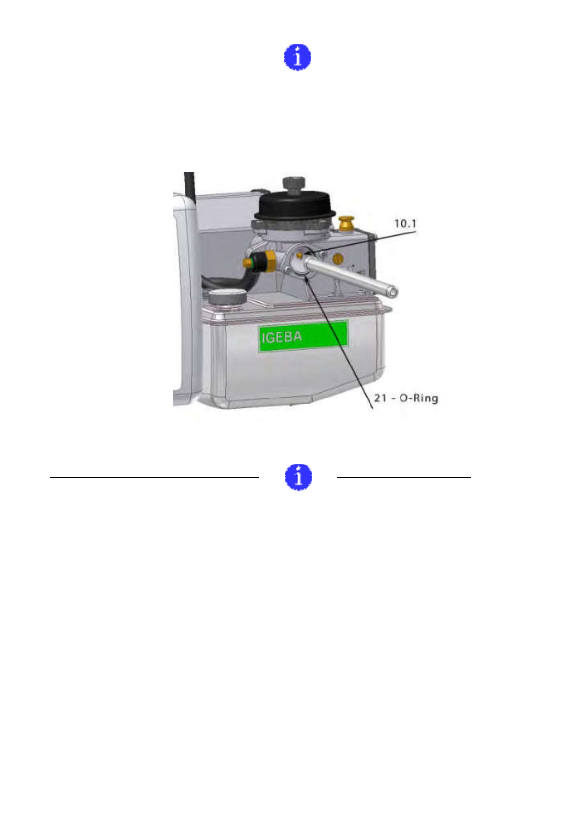
)
. ,
(. 20, . 10.1, . 42).
,
.
c.) Clean the inside of the mixing chamber
and mixing pipe. Remove combustion
residues with pipe cleaning tool. When
inserting the pipe cleaning tool into the
mixing chamber pay special attention to
the atomizer nozzle which enters the
mixing chamber from the right side (illus 20
pos.10.1 page 42). Take care and do not
damage the fuel atomizer nozzle with the
cleaning tool.
04/2010 1.0 42 72
,
. 20, . 21.
The O-Ring has to be placed like shown in
iIlus.20 pos.21 in the carburettor housing.
. 20
- . 69
illus 20.
SP list page 69
:Maintenance of the pump:
1-2 ( .
29, . 49).
(1)
(2).
•
(. 29, . 2.4)
.
. ,
.
•The maintenance of the pump has to
be performed one or two times per year.
(illus. 29 page 49)
Unscrew the cap by turning it counter-
clockwise (1.) and pull the complete pump
spindle out of the pump tube afterwards.
• Check collar (illus. 29 pos. 2.4) of pump
spindle for proper position and replace if
damaged. Lubricate the collar with grease.
Mount the pump in reversed order.
This manual suits for next models
1
Table of contents


