8
pl
Instrukcja obsługi Monika 2, Rota www.igloo.pl
• Numer seryjny (NS)
• Datęprodukcji
• Typ (nazwa urządzenia)
oraz
• Datęzakupu urządzenia
• Opis problemu
• Dokładny adres i numer telefonu
wraz z numerem kierunkowym
do Państwa
• Termostat działa poprawnie
• Skraplacz nie jest zanieczyszczony, w razie potrzeby wyczyścić
• Temperatura otoczenia nie jest wyższa niż25ºC
• Minęło wystarczająco dużo czasu dla schłodzenia produktów
• Otwory wentylacyjne urządzenia nie sązablokowane
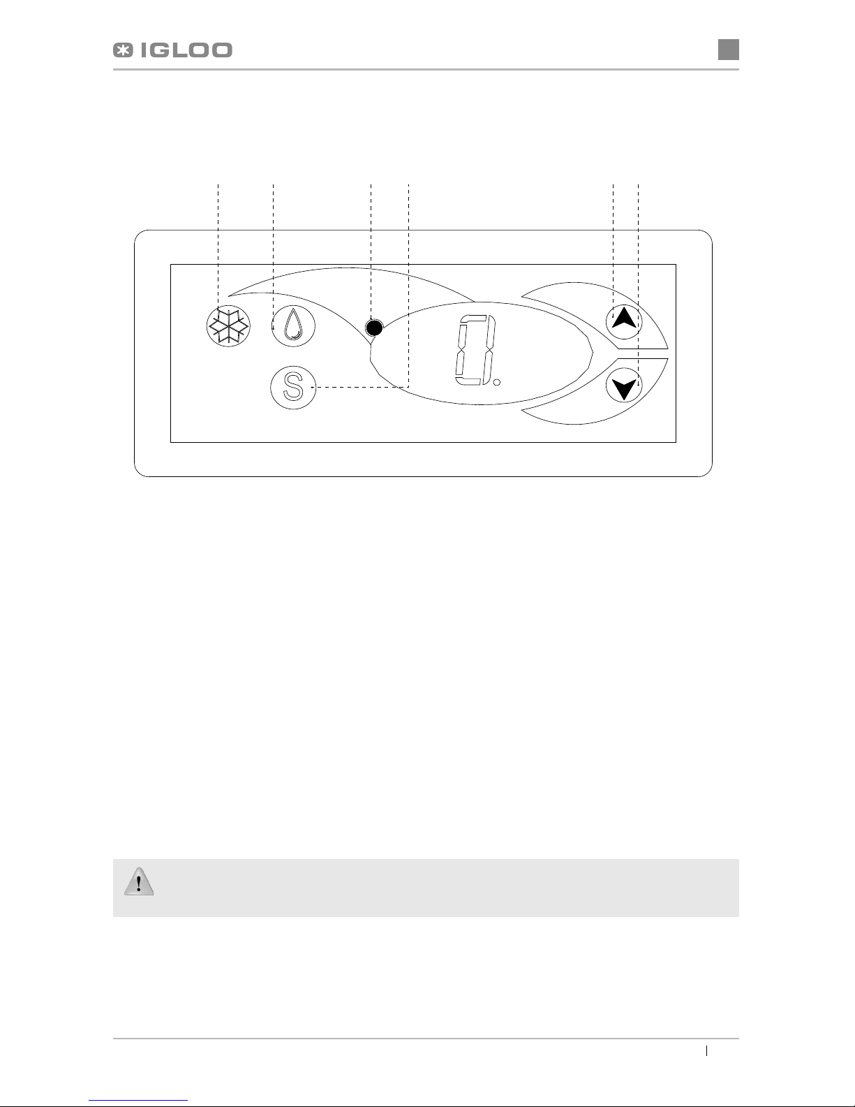
(Dotyczy term. „IGLOO”) Termostat wyświetla C0 lub C1 lub C2 zamiast temperatury:
Sytuacja taka ma miejsce, jeżeli zostałuszkodzony jeden z czujników regulatora wówczas mogąpojawićsię
następujące komunikaty:
• C0 –uszkodzenie czujnika temperatury wewnątrz komory –wezwaćautoryzowany serwis
• C1 –uszkodzenie czujnika parownika - wezwaćautoryzowany serwis
•
C2 –uszkodzenie czujnika alarmu skraplacza (lub uszkodzenie drugiego czujnika parownika) – wezwaćautoryzowany
serwis
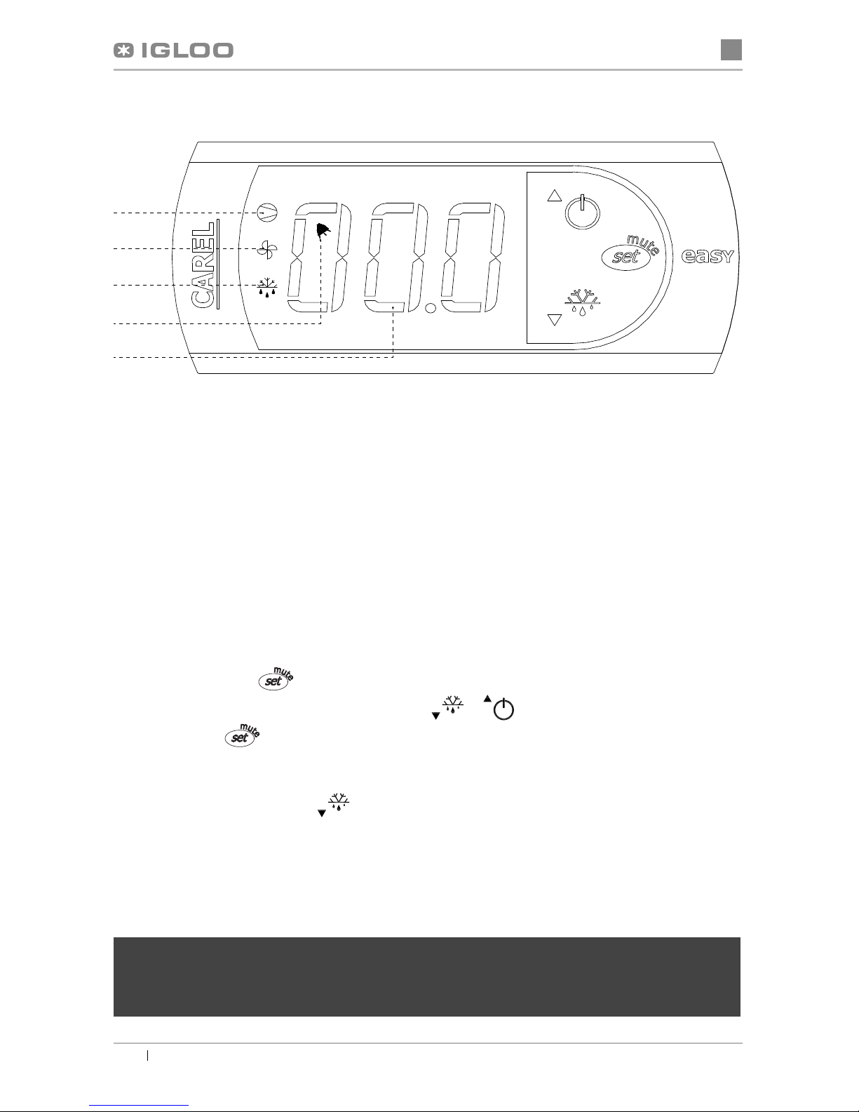
(Dotyczy term. „CAREL”) Termostat wyświetla E0 lub E1 lub L0 lub HI lub EE lub Ed lub DF zamiast temperatury:
• E0 -uszkodzenie czujnika temperatury wewnątrz komory- wezwaćautoryzowany serwis
• E1 -uszkodzenie czujnika parownika - wezwaćautoryzowany serwis
• L0 –alarm niskiej temperatury (niższej niżzadany zakres wewnątrz urządzenia) - wezwaćautoryzowany serwis
• HI - alarm wysokiej temperatury - wezwaćautoryzowany serwis
• EE -błąd wewnętrzny regulatora - wezwaćautoryzowany serwis
• Ed – przekroczenie max. czasu odszraniania
• DF – odszranianie w toku (to nie jest sygnałalarmowy)
(Dotyczy term. „IGLOO”) Urządzenie pracuje, włączona sygnalizacja dźwiękowa...- Upewnićsię, czy
• Skraplacz nie jest zanieczyszczony, w razie potrzeby wyczyścić
• Pracuje wentylator skraplacza
• Temperatura otoczenia nie przekracza 25ºC
Urządzenie pracuje zbyt głośno...- Upewnićsię, czy
• Urządzenie stoi stabilnie i jest prawidłowo wypoziomowane
• Przylegające do urządzenia meble nie drgająpodczas pracy sprężarki agregatu chłodniczego
Odgłosy wydawane przez urządzenia pracujące sązjawiskiem normalnym. W urządzeniach znajdująsię
wentylatory, silniki i sprężarki, które włączająsięi wyłączająautomatycznie. Każda sprężarka wytwarza
pewien hałas podczas pracy. Dźwięki te wytwarzane sąprzez silnik agregatu oraz przez czynnik
chłodniczy przepływający w obwodzie. Zjawisko to jest cechątechnicznąurządzeńchłodniczych i
nie oznacza ich wadliwej pracy.
Osadzanie siępary wodnej na szybach urządzenia przy dużej wilgotności względnej powietrza
powyżej 60% jest zjawiskiem naturalnym i nie wymaga wzywania serwisu!
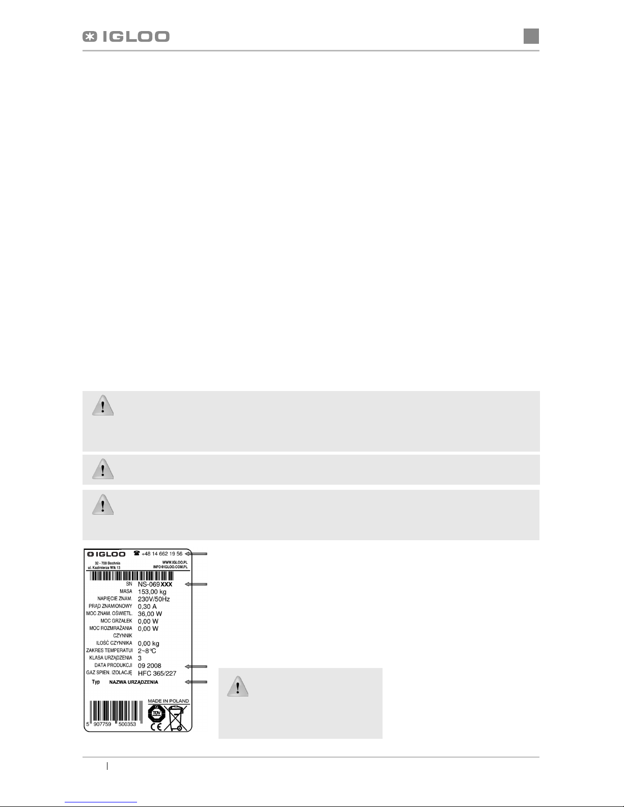
Rys.12 Tabliczka znamionowa
6.2. Serwis
Tel. do serwisu IGLOO: +48 (14) 662 19 56
lub +48 605 606 071
Jeśli po sprawdzeniu punktów opisanych w
rozdziale 6.1 „Identyfikacja i naprawa uste-
rek” urządzenie nadal nie działa prawidło-
wo, należy skontaktowaćsięz Serwisem
Technicznym firmy Igloo, podając dane z
tabliczki znamionowej Rys.12 (str.8)
Powyższy rysunek przedstawia
poglądowątabliczkęznamio-
nową, a dane w niej zawarte są
danymi przykładowymi nieodno-
szącymi siędo „Moniki 2”!
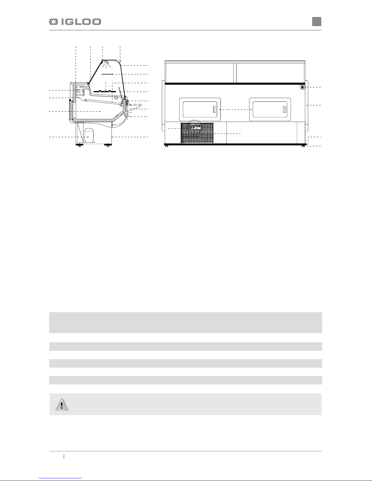
Tabliczka znamionowa znajduje sięz
tyłu urządzenia, w prawym, górnym
rogu poniżej blatu Rys.1/18 (str.2)
W przypadku przekroczenia warunków otoczenia wg trzeciej klasy klimatycznej (wilgotność
względna powietrza powyżej 60%) może występowaćzjawisko przelewania wody z układu z au-
tomatycznym odparowaniem kondensatu (wyparki). Przypadek ten nie oznacza wadliwej pracy
urządzenia i nie wymaga wzywania serwisu.


 Operation manual")