IGMI IEMCA GENIUS 226 Instruction manual

REL. DATA COD.
S/N
GENIUS 226
MANUAL FOR USE AND MAINTENANCE
GB
1 26/03/01 228005400

REL. DATA COD.
S/N
302.088
GENIUS 112
GENIUS 226
GUÍA OPERATIVA DEL TECLADO
PARA EL TECNICO AUTORIZADO
E
1 29/05/00 227005505

302.087
IEMCA division of IGMI SpA
48018 - Faenza (RA) - ITALY
Via Granarolo, 167
Tel. 0546/698000 - Fax. 0546/46338 ufficio commerciale
0546/46224 centralino
TLX 550879
E-mail: iemca@igmi.it
Web site: www.iemca.com
GENIUS 226
AUTOMATIC HYDRAULIC SUSPENSION
BAR FEEDER
MANUAL FOR USE AND MAINTENANCE
GB
© 2000 - This manual is composed by 103 pages, annexes excluded. It is forbidden to even partly reproduce this document without the Manufacturer's authorisation.

REL. DATA COD.
S/N
302.088
GENIUS 112
GENIUS 226
GUÍA OPERATIVA DEL TECLADO
PARA EL TECNICO AUTORIZADO
E
1 29/05/00 227005505

1
INDEX
302.087
1GENERAL INFORMATION
1.1. WARRANTY CONDITIONS............................... 3
1.2. MANUAL PURPOSE........................................... 3
1.3. MANUFACTURER AND BAR FEEDER
IDENTIFICATION................................................ 4
1.4. TECHNICAL ASSISTANCE............................... 4
1.5. ANNEXES ENCLOSED...................................... 4
2TECHNICAL INFORMATION
2.1. GENERAL BAR FEEDER DESCRIPTION...... 5
2.2. OPERATING CYCLE - General
description............................................................. 7
2.3. SAFETY DEVICES - Position and
description........................................................... 11
2.4. SAFETY PLATES - Position and
description........................................................... 12
2.5. VERSION DESCRIPTION ............................... 13
2.6. TECHNICAL SPECIFICATIONS..................... 14
2.6.1 Noise levels ........................................................ 18
2.7. ACCESSORIES - Description ......................... 18
2.7.1 Precision facing device - Description ............. 18
2.7.2 Axial displacement device - Description........ 19
2.7.3 Bush-holder device -
Description.......................................................... 20
2.8. DEVICES FOR SLIDING HEADSTOCK
LATHE - Description......................................... 20
2.8.1 Bar/headstock synchronizing device -
Description.......................................................... 20
2.8.2 Telescopic nose - Description ......................... 21
2.9. DEVICES FOR CAM LATHES -
Description.......................................................... 22
2.9.1 Headstock return device - Description........... 22
2.9.2 Cam box - Description ...................................... 22
2.9.3 Camshaft release device - Description .......... 23
3SAFETY PROCEDURES -
GENERAL INFORMATION
3.1. SAFETY GENERAL INSTRUCTIONS .......... 25
3.2. HANDLING AND INSTALLATION - Safety
procedures ......................................................... 25
3.3. ADJUSTMENTS AND SETTING UP - Safety
procedures ......................................................... 26
3.4. USE AND OPERATION - Safety
procedures ......................................................... 26
3.5. BAR FEEDER MAINTENANCE - Safety
procedures ......................................................... 26
4HANDLING AND INSTALLATION
4.1. PACKAGING...................................................... 27
4.2. LIFTING.............................................................. 27
4.3. INSTALLATION AREA - Characteristics....... 29
4.4. INSTALLATION OF BAR FEEDER -
Introduction ........................................................ 30
4.4.1 Support plates and feet - Installation............ 30
4.4.2 Height - Adjustment.......................................... 31
4.4.3 Preliminary positioning..................................... 32
4.4.4 Nose - Installation ............................................. 33
4.4.5 Levelling and alignment ................................... 34
4.4.6 Feeder fastening ............................................... 36
4.5. ACCESSORIES - Installation.......................... 37
4.5.1 Precision facing device - Installation.............. 37
4.6. DEVICES FOR SLIDING HEADSTOCK
LATHES - Installation....................................... 38
4.6.1 Bar-headstock synchronisation device -
Installation.......................................................... 38
4.6.2 Telescopic front nose - Installation................. 39
4.7. DEVICES FOR CAM LATHES -
Installation.......................................................... 40
4.7.1 Headstock return device - Installation............ 40
4.7.2 Cam box - Installation....................................... 41
4.7.3 Camshaft release device ................................. 42
4.8. LUBRICANT OIL - Filling................................. 43
4.9. ELECTRIC CONNECTION.............................. 43
4.10. PNEUMATIC CONNECTION.......................... 44
4.11. SELF-LEARNING DIMENSIONS -
Programming ..................................................... 44
Operations described in paragraphs showing this symbol, must be performed by qualified and skilled personnel
only. Any other operation can be performed either by qualified personnel or by professional bar feeder operators.

2
INDEX
302.087
5ADJUSTMENTS AND SETTING-UP
5.1. ADJUSTMENT AND SETTING-UP -
Foreword............................................................. 45
5.2. GENERAL ADJUSTMENTS - Foreword........ 45
5.2.1 Feed chain - Adjustment................................... 46
5.2.2 Drive belt - Adjustment ..................................... 46
5.3. SETTING-UP THE BAR FEEDER
ACCORDING TO THE BAR TO
BE MACHINED................................................... 47
5.3.1 Guide channels, bar pusher and collet -
Replacement ...................................................... 49
5.3.2 Half-bushings - Replacement .......................... 55
5.3.3 Nose - Replacement ......................................... 56
5.3.4 Bar magazine - Adjustment.............................. 57
5.3.5 Bar selection device - Adjustment................... 58
5.3.6 Clamps - Adjustment......................................... 59
5.3.7 Clutch thrust - Adjustment................................ 61
5.4. PRECISION FACING DEVICE -
Adjustment.......................................................... 63
5.5. CAM BOX - TIMING.......................................... 64
6BASIC INFORMATION
6.1. DESCRIPTION OF THE CONTROLS ........... 67
6.2. DESCRIPTION OF KEYBOARD
CONTROLS........................................................ 68
6.3. INDICATOR LIGHTS - Description of
indications........................................................... 70
6.4. BARS TO BE MACHINED -
Characteristics and preparation ...................... 70
6.5. FEEDER SET-UP AND AUTOMATIC
CYCLE START .................................................. 72
6.5.1 Bar magazine - Filling....................................... 73
6.5.2 Lubrication oil - Flow adjustment..................... 74
6.5.3 Starting the automatic cycle............................. 74
6.5.4 Guide channel opening/closing mode............ 75
6.5.5 Cycle actuation mode in
the “STEP-BY-STEP” function......................... 77
6.6. FEEDER STOP.................................................. 77
7BAR FEEDER MAINTENANCE
7.1. MAINTENANCE - GENERAL RULES........... 79
7.2. SCHEDULED MAINTENANCE ...................... 80
7.2.1 Revolving tip and collet - Check ..................... 80
7.2.2 Lubricating oil - Level check............................ 81
7.2.3 Lubricating oil - Change................................... 81
7.2.4 Clutch oil - Checking......................................... 82
7.2.5 Clutch oil - Change ........................................... 82
7.2.6 Clutch disks - Checking for wear.................... 83
7.2.7 Feed motor brushes - Checking for wear...... 84
7.2.8 Air filter unit - Check ......................................... 85
7.3. AXIAL DISPLACEMENT DEVICE - Use....... 86
8TROUBLES - CAUSES - CURES
8.1. GENERAL FAULTS.......................................... 87
8.2. BAR MAGAZINE - Faults................................. 87
8.3. INSERTION IN THE COLLET - Faults.......... 88
8.4. BAR FEEDING - Faults.................................... 88
9PART REPLACEMENT
9.1. FEED CHAIN - Replacement.......................... 89
9.2. CLUTCH DISKS - Replacement..................... 89
9.3. FEED MOTOR BRUSHES -
Replacement...................................................... 89
9.4. PLC BATTERY - Replacement....................... 90
9.5. KEYBOARD BATTERY - Replacement ........ 91
9.6. FEED MOTOR DRIVE - Replacement.......... 92
9.7. RECOMMENDED SPARE PARTS - List...... 93
LIST OF AFTER-SALES
CENTERS..................................................... 95
Operations described in paragraphs showing this symbol, must be performed by qualified and skilled personnel
only. Any other operation can be performed either by qualified personnel or by professional bar feeder operators.
3
302.087
1
GENERAL INFORMATION
Before carrying out any servicing whatsoever
on the bar feeder, it is of the utmost impor-
tance to read this manual carefully.
1.1. WARRANTY CONDITIONS
The warranty validity is conditional on good alignment
between the bar feeder and the lathe and the subse-
quent bar feeder fixing to the ground with expansion
plugs, as explained in the sections “Levelling and
alignment” and “Feeder fastening”.
1.2. MANUAL PURPOSE
This manual has been written and supplied by the
manufacturer and is integral part of the bar feeder and
of its equipment.
The compliance with the instructions contained herein
ensures the operator and bar feeder safety as well as
a running economy and a longer life of the bar feeder
itself.
In order to allow a quick search of contents, consult the
descriptive index.
Particularly important parts of this manual have been
highlighted in bold type and preceded by the following
symbols:
DANGER - WARNING: shows impending dan-
ger which might cause serious harm, hence it is
necessary to pay the greatest attention.
CAUTION: n order to avoid accidents or damag-
es to property, suitable measures shall be adopt-
ed.
INFORMATION: Information: technical instruc-
tions having particular importance.
For a quick search according to subjects, consult the
table of contents and/or the index.
Two more manuals are supplied along with this manu-
al, which contains all the operating instructions and
maintenance instructions for the bar feeder: the “Key-
board instruction manual” and the “Quick procedure”
manual.
The “Keyboard instruction manual” contains all the in-
structions on how to use the installed software.
The “Quick procedure” manual contains all the mini-
mum required instructions to use the bar feeder and its
software.

4
1
GENERAL INFORMATION
302.087
1.3. MANUFACTURER AND BAR FEEDER IDENTIFICATION
A- Manufacturer’s identification
B- CE conformity marking
C- Year of manufacture
D- Bar feeder model
E-Serial number
F-Feeding voltage
G- Mains frequency
H- Amperage
L-Alternate driving voltage
M- Direct driving voltage
N- Bar feeder weight.
INFORMATION: Always provide the Manufac-
turer with the above mentioned specifications in
order to obtain information or whenever ordering
spare parts, etc.
1.4. TECHNICAL ASSISTANCE
For any requirement, contact one of the centres listed
in our ”CUSTOMER SERVICE CENTRE LIST”.
INFORMATION: As far as technical servicing rel-
evant to the bar feeder is concerned, always specify
the technical data printed nameplate.
1.5. ANNEXES ENCLOSED
Keyboard instruction manual.
Quick-reference guide.
GUIDE CHANNELS –BAR PUSHER –REVOLVING
TIPS –COLLETS. Choice manual.
Wiring diagram.
Lathe coupling instructions.
C L H N
A
D
F
B
M
G
E
IDM-3020870010.tif

5
302.087
2
TECHNICAL INFORMATION
2.1. GENERAL BAR FEEDER DESCRIPTION
The GENIUS automatic bar feeder is used in the ma-
chine-tool industry and in particular, for automatic lathe
feeding. It is particularly suitable for feeding fixed or
sliding headstock lathes, numerical control or cam
lathes.
The working cycle is controlled by a control panel with
built-in PLC, which is able to dialogue with the lathe
control.
The hand-held keyboard facilitates programming and
enables to control bar feeder functions without having
to leave the lathe
The bar feeder can be used to feed bars, pipes and
various sections.
The guide channel is fully closed during machining; a
pump is provided to maintain a continuous oil flow in-
side the channel, creating a hydrodynamic support ef-
fect; these characteristics allow the bar to rotate at a
high r.p.m. number, with no vibrations and no surface
damaging.
The use of a d.c. motor and adjustable clutch make it
possible to adjust feed speed and thrust to optimum
values at every moment of the working cycle.
6
2
TECHNICAL INFORMATION
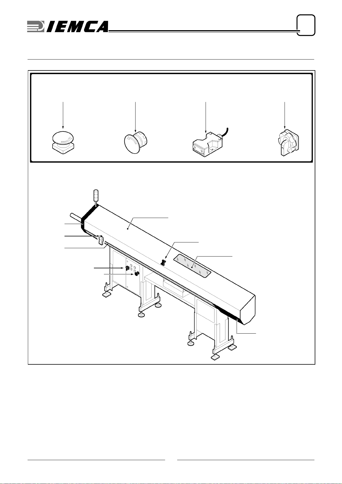
302.087
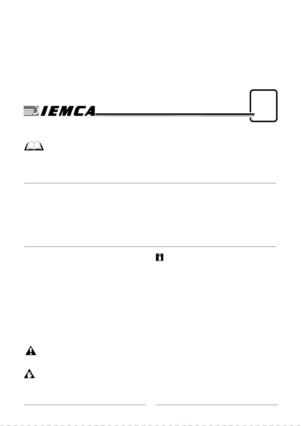
❑Main parts
A - Magazine; where bars are stored.
B - Bar selection device; it allows the first bar to be
lowered into the guides and holds back the re-
maining bars in the magazine.
C-Guides
; they guide the bars during machining.
D - Bar-pusher; it pushes the bar during machining.
E - Feed chain; it transmits motion from the drive
system to the bar-pusher.
F - Drive system; it drives the bar-pusher and the bar
feeder parts controlling bar insertion into the collet
and subsequent bar remnant extraction. It also
drives the bar feeder parts controlling guide open-
ing/closing and bar selection.
G- Clutch
; it transmits motion from the drive system
to the feed chain. It can be set to obtain thrust ad-
justment.
H - Sensors unit; enable control and command of
bar feeder movements.
L-Clamps
; they hold the bar during bar introduction
in and extraction from the bar-pusher collet.
M - Facing device; it sends a signal at bar passage.
N - Remnant collection box; bar remnants are
dropped into this box after extraction from the bar-
pusher collet.
P - Lubricating pump; it delivers oil to the guides.
Q - Oil recovery device; it collects oil flowing out of
the guides.
R - Hand-held keyboard; it allows bar feeder pro-
gramming and function actuation.
S - Electric cabinet; it contains the electric switch-
board.
T-Lathe
M
R
T
S
P
N
A
D
B
C
L
G
E
F
E
H
E
Q
IEMCA228510011
7
2
TECHNICAL INFORMATION
302.087
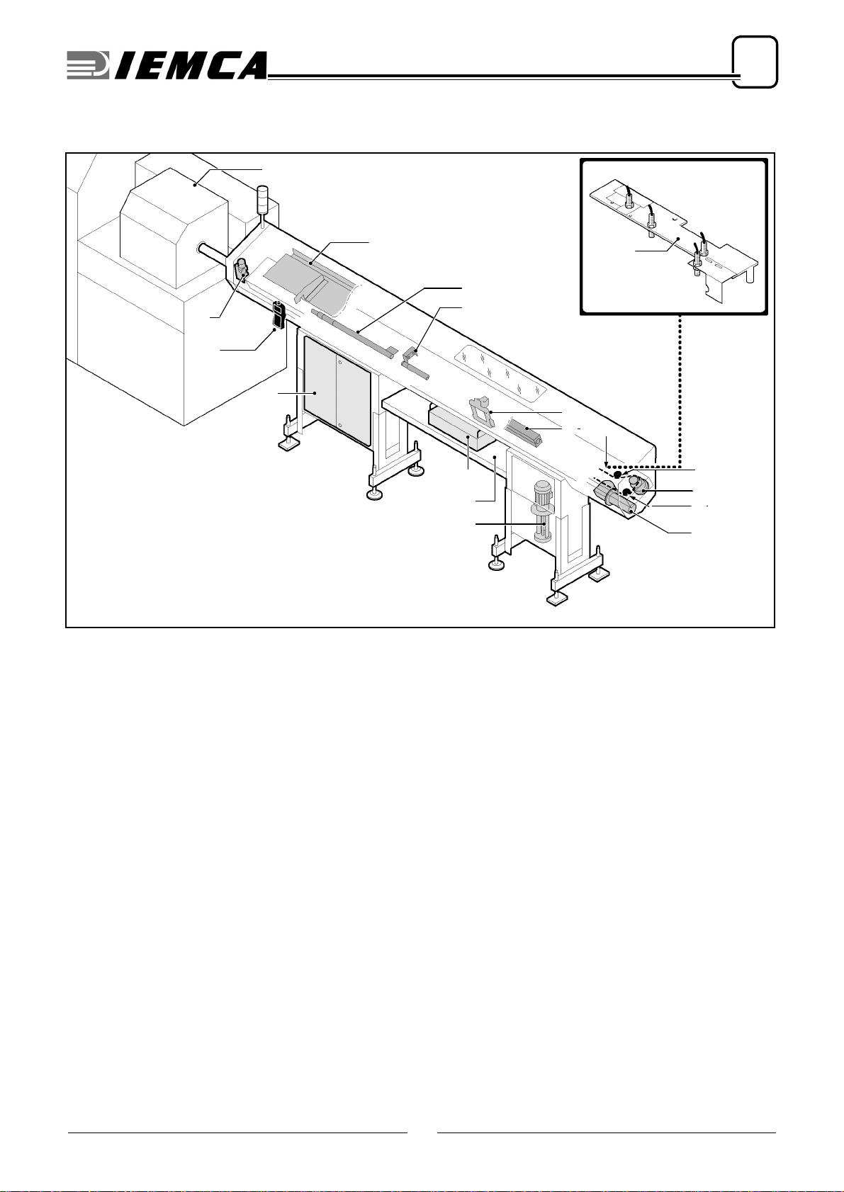
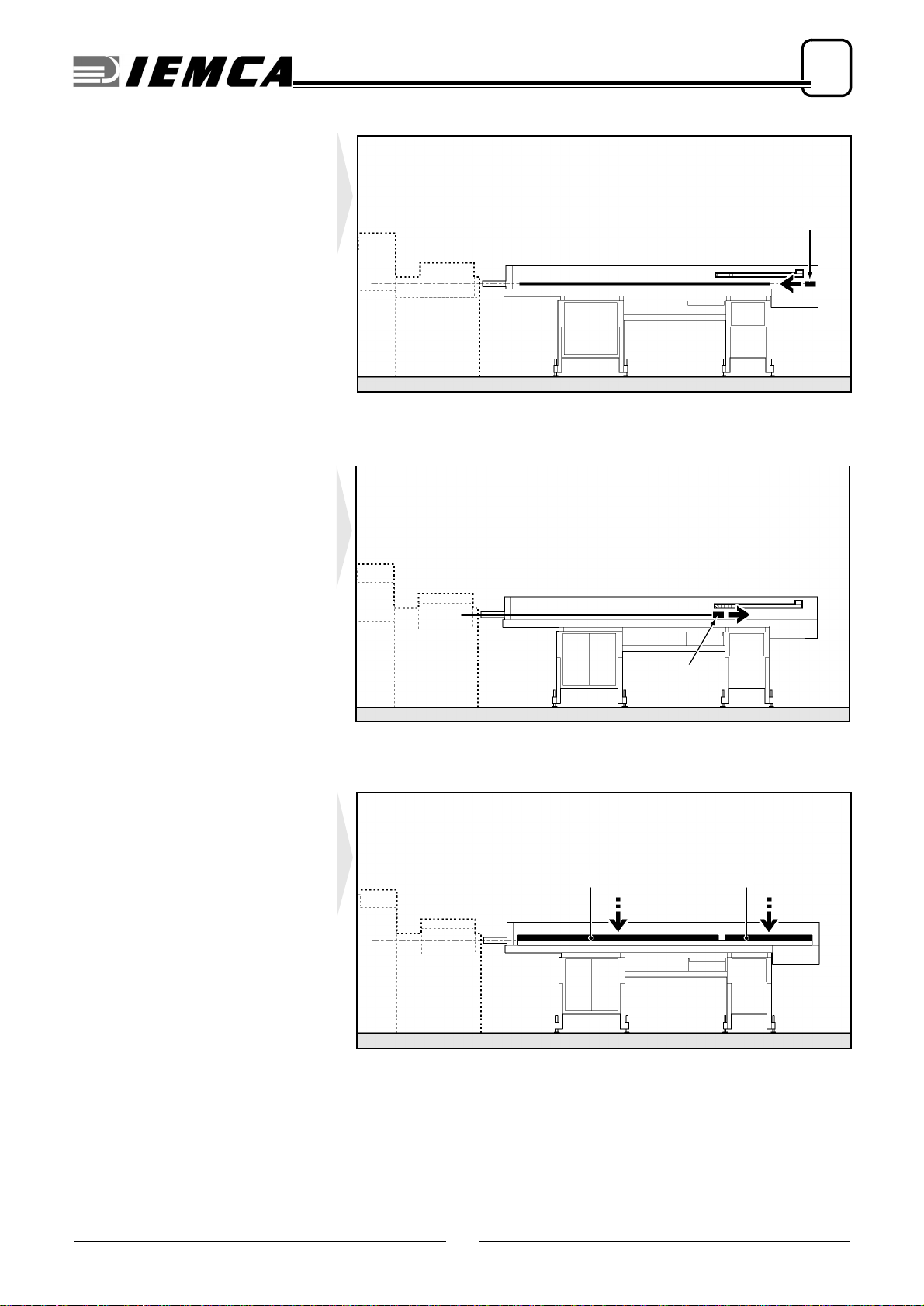
2.2. OPERATING CYCLE - General description
In the automatic operation mode, bar
feeder movements are controlled in
the sequence described below:
Phase 1
The bar-pusher A feeds bar B in the
lathe by following lathe impulses un-
til bar end.
Phase 2
The bar-pusher A and remnant C
are in their forwards limit stop posi-
tion.
Phase 3
The bar-pusher Aand remnant C
reach their backwards limit stop po-
sition.
The clamps Dclose and the bar-
pusher moves back; the remnant is
extracted from the collet. The
clamps open and the remnant is
dropped into the box E.
B A
IDM - 3020870030.tif
C A
IDM - 3020870040.tif
A
CD
D
CA
E
IDM - 3020870050.tif
8
2
TECHNICAL INFORMATION
302.087
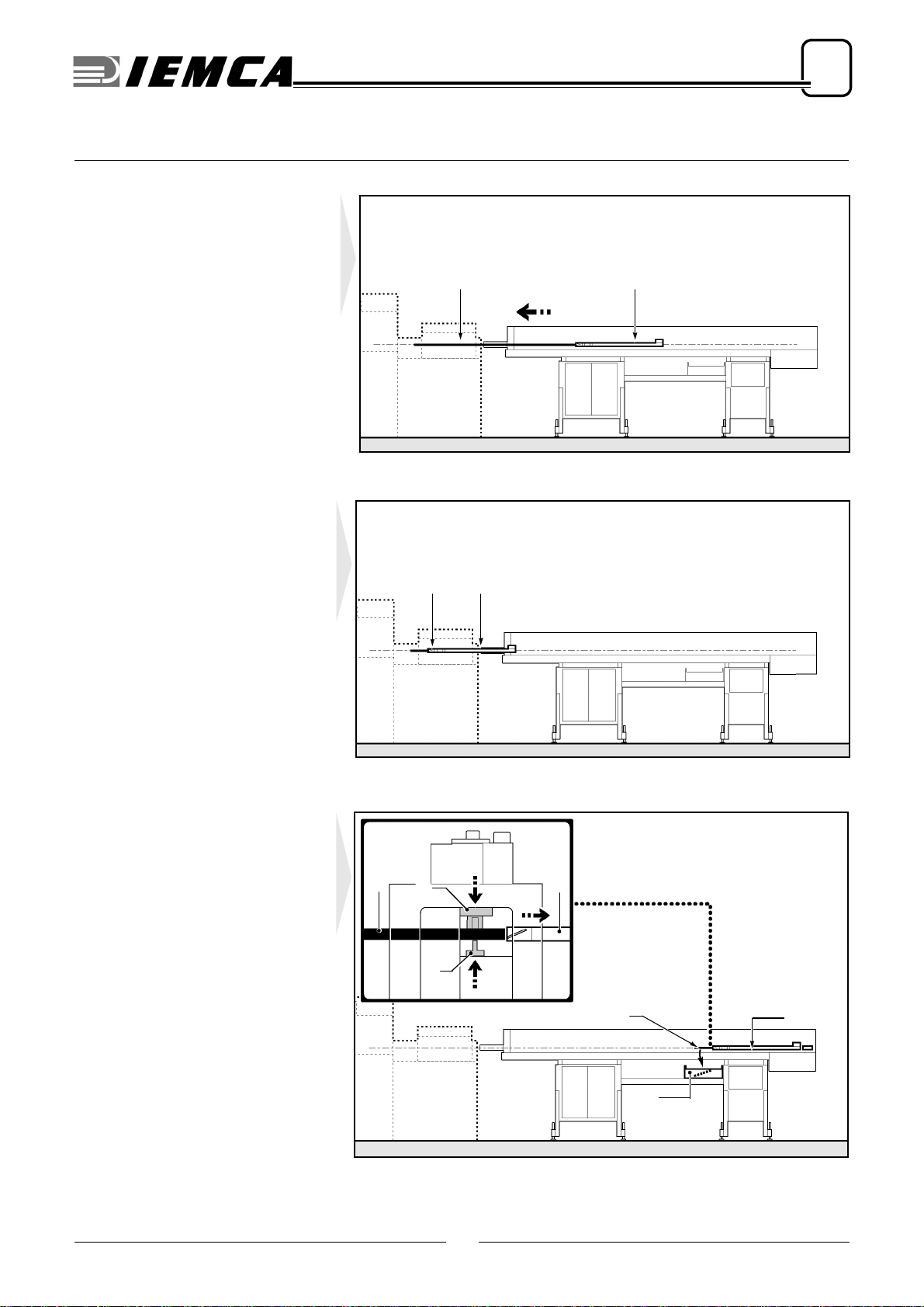
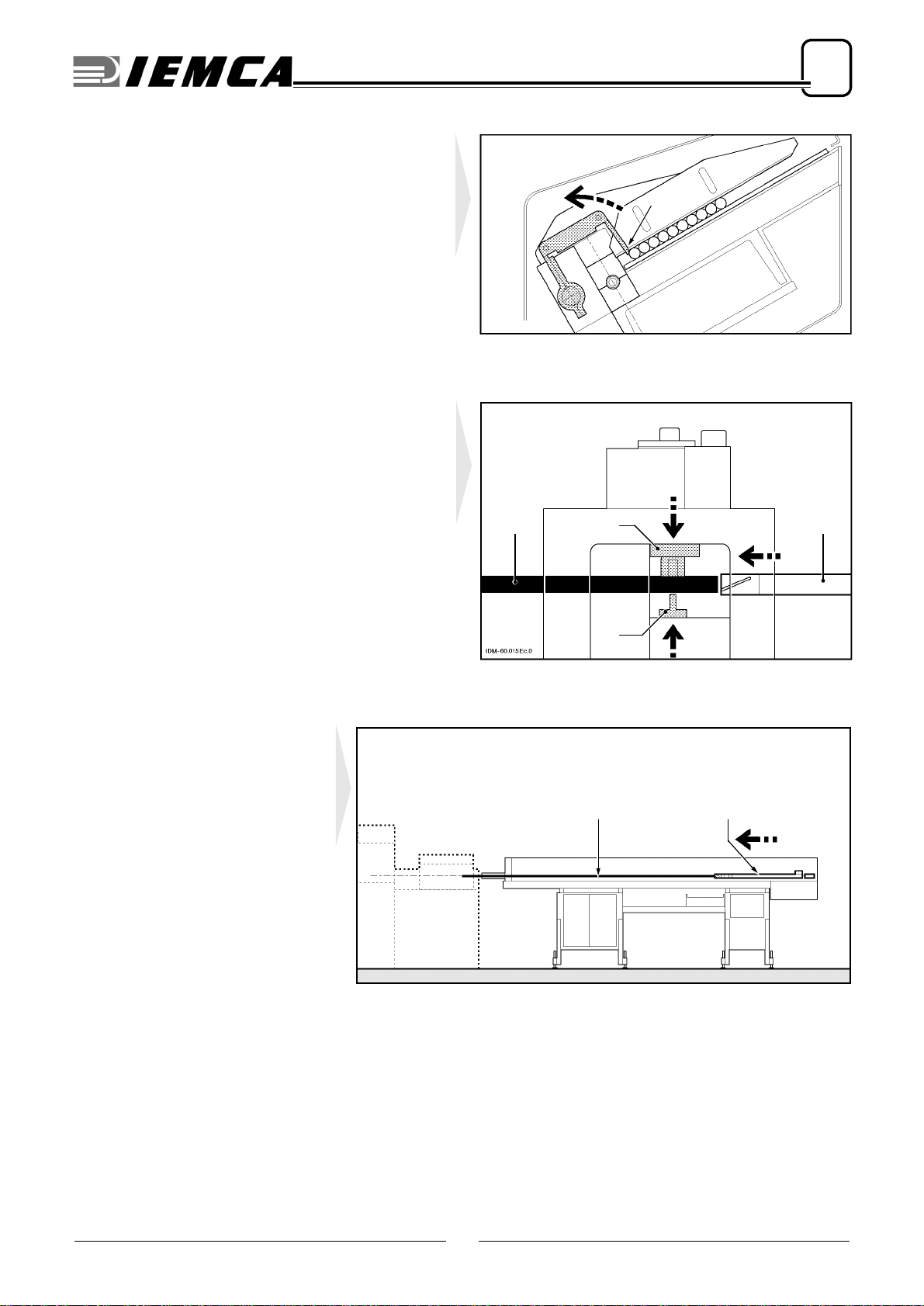
Phase 4
Clamps Dclose again to perform
remnant Cextraction check.
If the remnant is still inserted in the
bar-pusher collet, the feeder stops;
otherwise, it continues its cycle.
Phase 5
The bar selector Fis lowered, and all the bars in the
magazine are held back except for the first bar G.
Phase 6
The front top guide channels Hand rear top guide
channels Lrise up together with the bar pusher M, and
bar G falls into the lower guide.
D
D
C
IDM - 3020870060.tif
F
G
IEMCA228510211
H
MG
L
IEMCA228510221
9
2
TECHNICAL INFORMATION
302.087
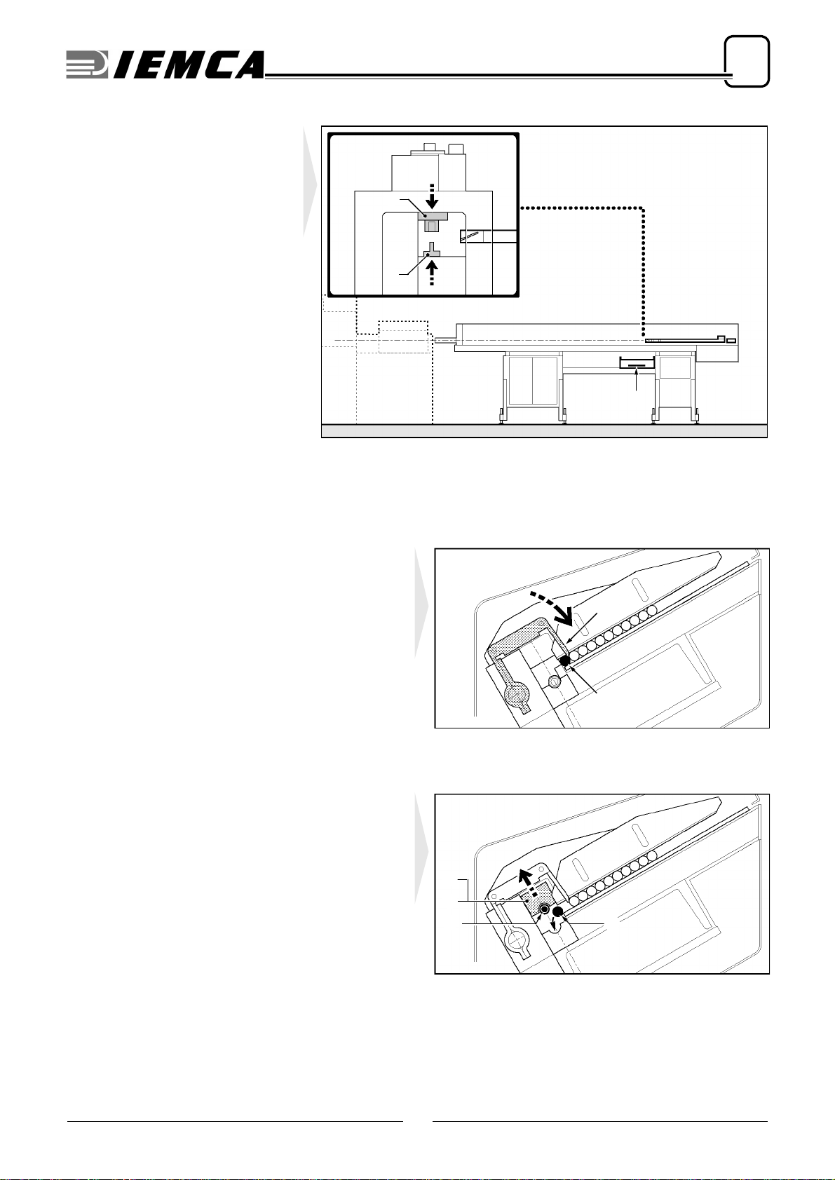
Phase 7
The small pusher truck N starts its
stroke.
Phase 8
When the small pusher truck N com-
pletes its stroke, the required space
has been created for bar-pusher in-
sertion.
The small pusher truck executes its
return stroke.
Phase 9
The front top guide channels Hand
rear top guide channels L close; the
bar pusher places itself along the bar
axis.
N
IDM - 3020870070.tif
N
IDM - 3020870080.tif
LH
IDM - 3020870090.tif
10
2
TECHNICAL INFORMATION
302.087
Phase 10
The bar selector Frises.
Phase 11
The clamps Dclose, the bar-pusher Amoves for-
wards; the bar Gis inserted into the bar-pusher collet.
Phase 12
The bar-pusher A and bar G execute
their facing stroke. A new automatic
work cycle is started.
F
IEMCA228510231
D
D
AG
AG
IDM - 3020870100.tif
11
2
TECHNICAL INFORMATION
302.087
2.3. SAFETY DEVICES - Position and description
A B-Emergency button; by working it, all feeder and
lathe functions are stopped in an emergency situ-
ation.
C - Interlocked sliding guard: connected with the mi-
croswitch C1.
When this guard is opened, the bar feeder and lathe
will stop.
Onlyifthisguardisopenedduringthe feedingphase
will the bar feeder and lathe continue towork without
this implying any risks for the operator.
D - Fixed guard: made of transparent material to allow
visual inspection of the bar magazine area and the
terminals.
E - Fixed guard: prevents unintentional access to
moving parts.
F - Fixed guard: it prevents accidental access to the
drive area.
G - Fixed guard: iprevents unintentional access to
moving parts.
H-Mainswitch
: disconnects the electric supply source
when operations are being performed on the electric
panel, and when the feeder is not in use.
C
C1
F
HA C1B
H
B
D
IDM - 3020870130.tif
A
G
E
12
2
TECHNICAL INFORMATION
302.087
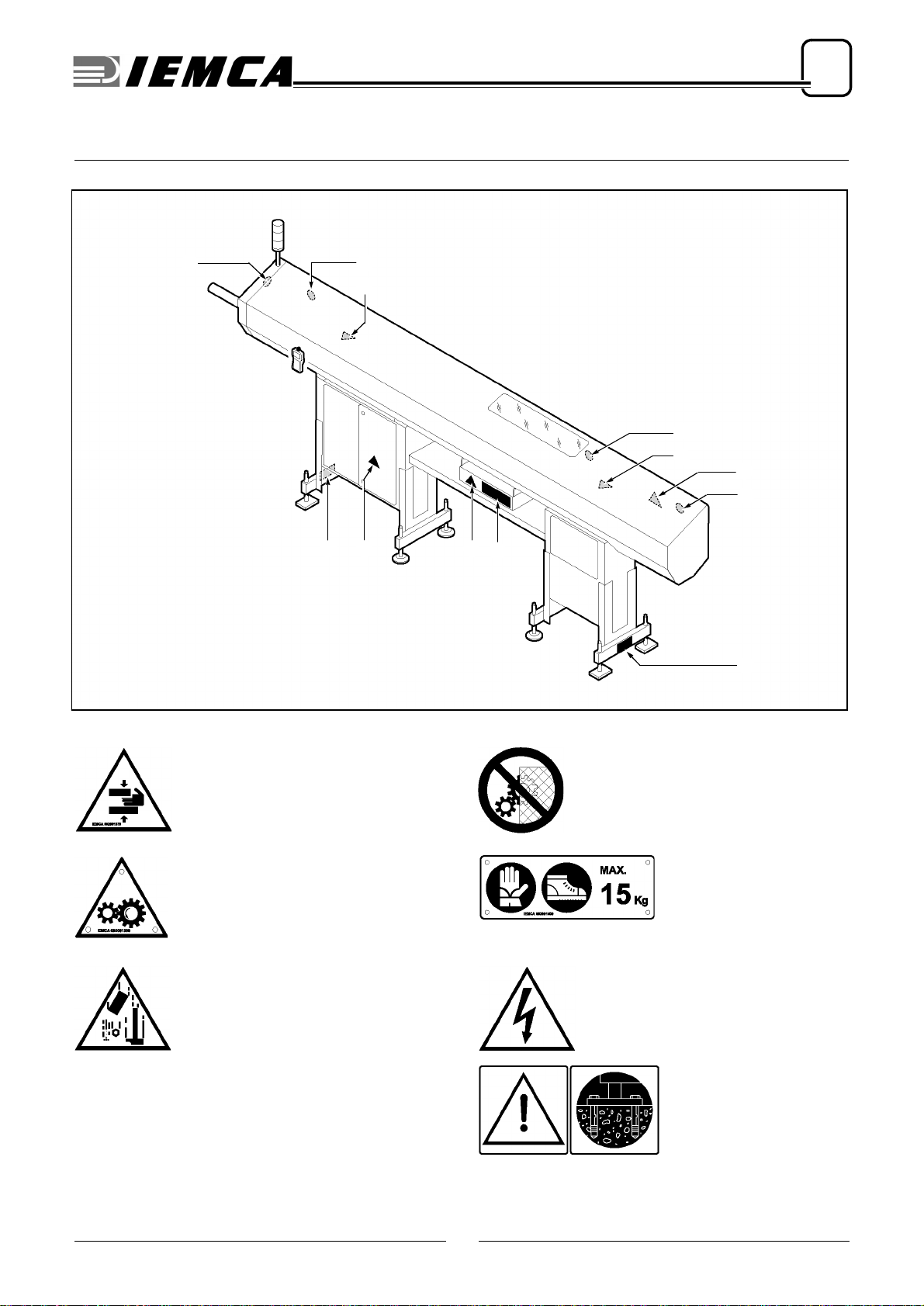
2.4. SAFETY PLATES - Position and description
A-Danger of arm crushing.
B-Beware of running parts.
C-Danger of material fall.
D-Do not remove safety barriers.
E-Wear working gloves
and shoes.
Do not lift manually
loads exceeding 15 kg.
F-Danger of electric shock.
G- Warning: fix the bar
feeder to the ground.
B
D
D
A
D D
A
CE
IDM - 3020870140.tif
G
FG
13
2
TECHNICAL INFORMATION
302.087
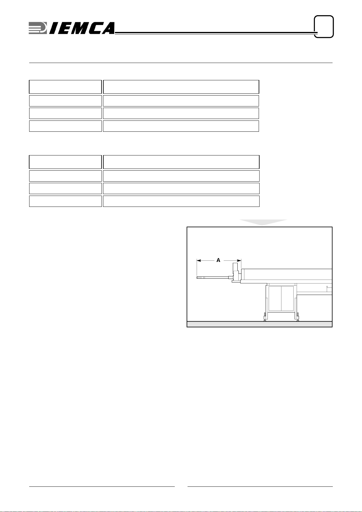
2.5. VERSION DESCRIPTION
Table 1. Maximum bar length
Version Max. length mm (ft)
32 3210 (10,5)
37 3730 (12,2)
42 4250 (13,9)
Table 2. Max. bar-pusher extension
Version
A
- Max extension (mm)
N958
L1218
LL 1478
IEMCA228510021
14
2
TECHNICAL INFORMATION
302.087
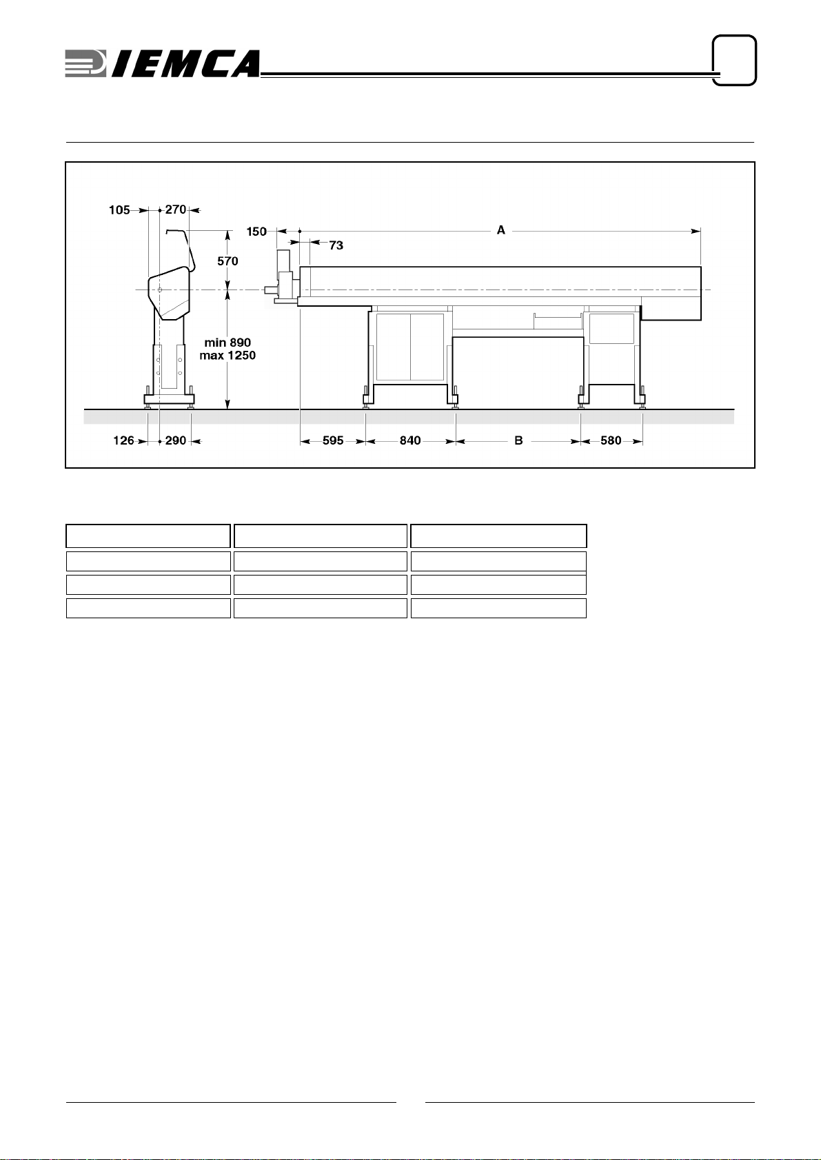
2.6. TECHNICAL SPECIFICATIONS
Table 3. Overall dimensions
Version
A
(mm)
B
(mm )
32 3755 1185
37 4275 1705
42 4795 2225
IEMCA228510031
15
2
TECHNICAL INFORMATION
302.087
Table 4. General technical data
Round bar diameter min 2 mm (5/64”) max 26 mm (1”)
Square bar side min 2 mm (5/64”) max 18 mm (45/64”)
Hexagonal bar height
(key socket) min 2 mm (5/64”) max 22 mm (7/8”)
Minimum bar length 1500 mm
Maximum bar length mod 32 - 3210 mm (10,5 ft)
mod 37 - 3730 mm (12,2 ft)
mod 42 - 4250 mm (13,9 ft)
Magazine capacity
(working width) 265 mm
(es: 22 barre da ø 12 mm)
Maximum bar remnant
length 400 mm
Bar change time 30 sec
Maximum feed speed 1250 mm/sec
Supply voltage 230/400 Volt
Control voltage 24 Volt
Installed power 1.5 kW
Air pressure 6 bar
Quantity of oil 40 l
Dry weight mod 32 - 650 kg
mod 37 - 700 kg
mod 42 - 750 kg
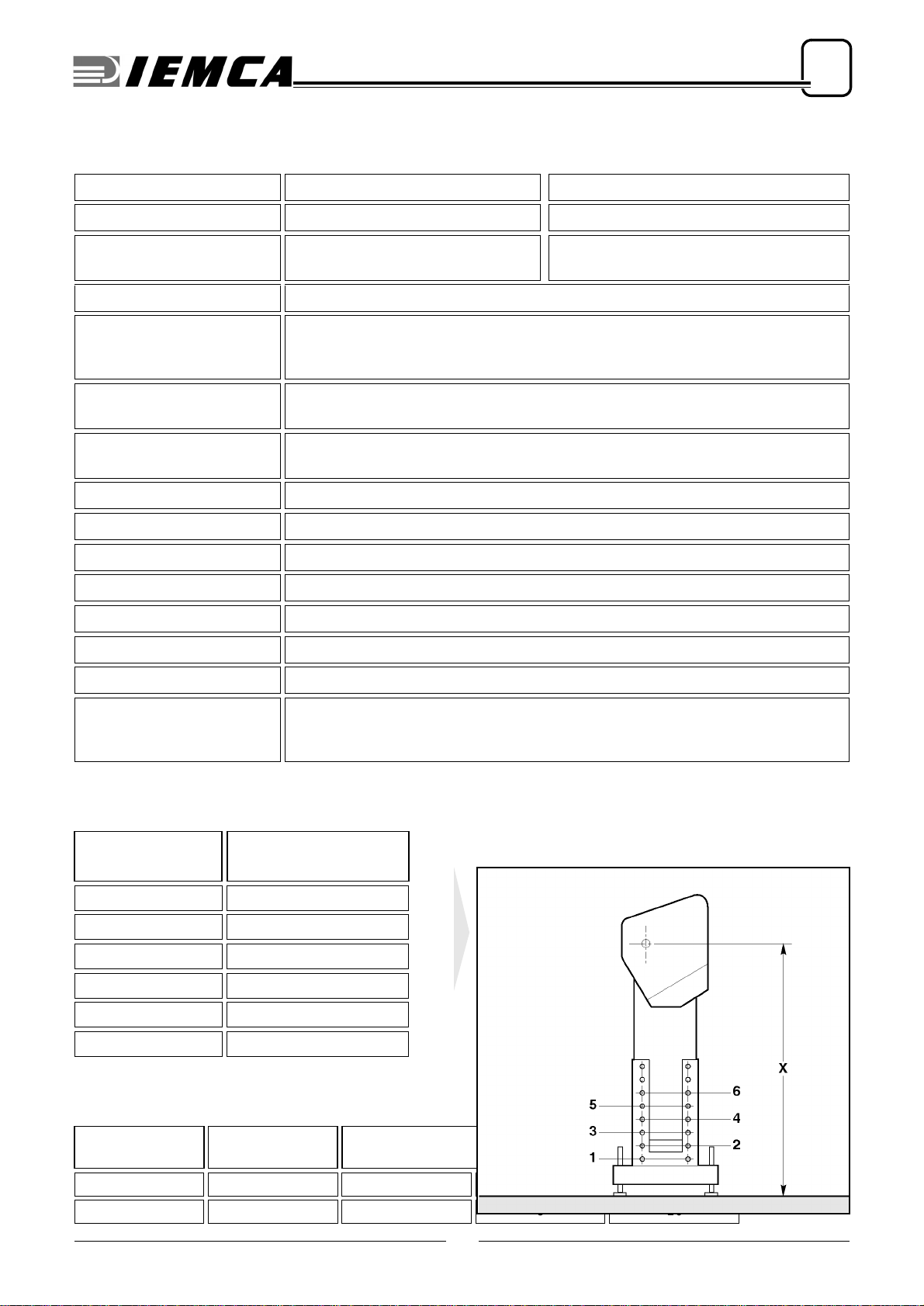
Table 5. Working axis height
Position of bottom
screws
X
(mm)
1890÷949
2950÷1009
31010÷1069
41070÷1129
51130÷1189
61190÷1250
Table 6. Diameters of guides, bar-pusher, bars and pipes
Guide
diameter (mm) Bar-pusher
diameter (mm) Bar diameter (mm) Largest pipe
diameter (mm) (*)
87,5 26,5 7
11 10 3 9 10

16
2
TECHNICAL INFORMATION
302.087
(*) valid also for prepared bars or normal bars machined with front remnant ejection
CAUTION: Barstock diameters for any guide
channel are only given as an example. A barstock
diameter approximately 5 mm smaller than the
guide channel diameter may cause vibration and
failure to the bar feeder. Therefore, it may be nec-
essary to slow down the bar rotation speed or to
change the guide channel diameter in order to ob-
tain the best performance for a specific applica-
tion.
13 12 411 12
18 15 513,5 17
22 20 518,5 20
26 25 823 25
28 27 825 26
30 29 826 26
Table 6. Diameters of guides, bar-pusher, bars and pipes
Guide
diameter (mm) Bar-pusher
diameter (mm) Bar diameter (mm) Largest pipe
diameter (mm) (*)
Table of contents
Popular Industrial Equipment manuals by other brands


Eaton
Eaton CODMV Series Instruction leaflet

ABB
ABB HT608847 Operation manual

GREER Company
GREER Company MicroGuard RCI 510 troubleshooting manual

Berker
Berker RolloTec 2911 operating instructions

Zaber Technologies Inc.
Zaber Technologies Inc. VSR-E Series user manual

Siemens
Siemens SINUMERIK 808D ADVANCED T user manual