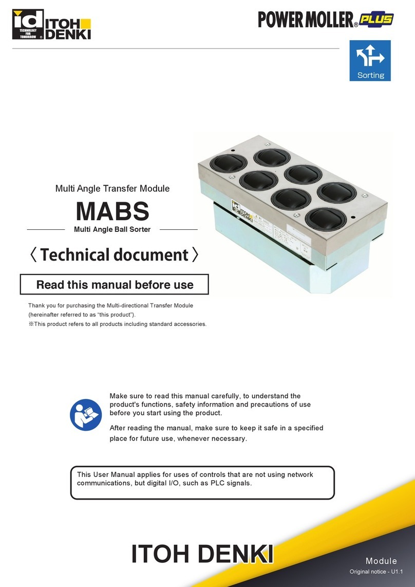
ITOH DENKI MABS User manual

2 Great Valley Blvd., Wilkes-Barre, PA 18706
Office Ph: 570-820-8811
Fax: 570-820-8838
www.itohdenki.com
Make sure to read this manual carefully before using, and start using only after you have
understood all the product’ s functions, safety information and precautions.
After reading the instructions, store the booklet in a designated location for readily accessing at
any time.
Multi-Angle Ball Sorter
Specifications subject to change without notice
Operating Instructions
Thank you for purchasing the Multi-directional Transfer Module (hereinafter
referred to as “this product”).
※This product refers to all products including standard accessories.
This User Manual is intended to be written under control using not network
communications, but digital I/O, such as PLC signals.

table of contents
Introduction
3-4
Procedures
5
Safety Precautions
6-10
Advance Preparation
11-15
Product Check
16
Structures
17
Installation/Wiring
-Before Installation
-Installation
-Wiring
18-31
IB-E06F-M1 settings
-Setting Preparation
-Property Settings
32-42
Control/Operation
-Before Starting Control
-About Swing Control
-Basic Operation
-What to Do Before Operation
43-49
Maintenance/Inspection
-Controller's LED Display
-Checking and Releasing Errors
-Before Replacement Work
-Replacement of the Transfer Ball Element Set/Grease Filling Procedure
50-58
Troubleshooting
59-60
Appendix
-Appendix 1: Product Specifications
-Appendix 2: Replacement Parts/Options
-Appendix 3: Residual Risk List/MAP
61-64
Subject page
2 Great Valley Blvd., Wilkes-Barre, PA 18706
Office Ph: 570-820-8811
Fax: 570-820-8838
www.itohdenki.com

2 Great Valley Blvd., Wilkes-Barre, PA 18706
Office Ph: 570-820-8811
Fax: 570-820-8838
www.itohdenki.com
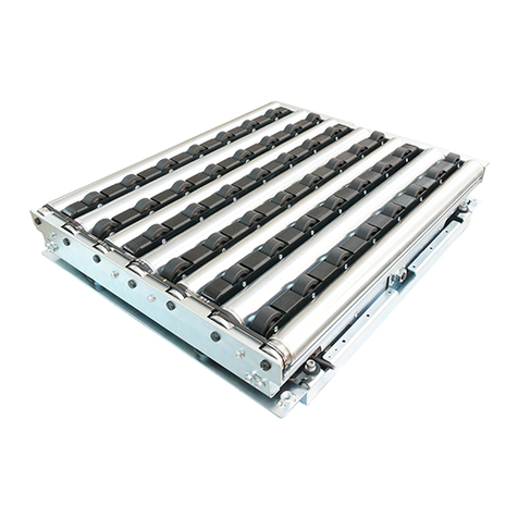
This product is a module to enable the user to divert totes.
This compact diverting module can set the diverting angle freely.
All-electric control. No pneumatics, which do not require compressor.
introduction
operation description (when diverting):
Features:
Load
Discharge
The transfer ball section swings to the
diverting direction
The transfer ball section swings to the
straight direction

2 Great Valley Blvd., Wilkes-Barre, PA 18706
Office Ph: 570-820-8811
Fax: 570-820-8838
www.itohdenki.com
Signal Input/Output Type
NPN
PNP
Included controller model
IB-E06F-N-UL-M1
IB-E06F-P-UL-M1
This product is designed as a general industrial device. Do not use for other applications. We do not take any
responsibility for any damage that may result from the disregarding of these warnings.
In the event that an accident results from the use of this product, we do not compensate for any damage,
including abnormalities of equipment, connection devices, and/or software, any damage resulting from
malfunctions, and/or any other secondary damage.
Caution : Installation, operation and usage of ITOH DENKI MDRs in combination with a control card designed by a
third party could result in fatal phenomena such as fire, electric shock, injuries, etc. which are out of the
responsibility of ITOH DENKI.
introduction
notes on industrial property rights:
disclaimer:
There are some examples of parts that need to be prepared by customers, as explained within this manual.
However, this does not provide any guarantee against the existence of any rights, such as our industrial
property rights, or those of other companies.
*
1
:
International Organization for Standardization
*
2
:
This indicates that even though events that would result in serious injury occur infrequently under
assumed risk environment, there is a high probability to avoid danger if you observe the safety contents
described in this manual.
This product is based on the performance level “C”*2 in ISO-13849-1*1.
notes on technical support:
We respond to technical inquiries based on the contents described within this manual, and on this product
within the range of general items for this product unit.
There are some descriptions in this manual, about parts, equipment, and wiring arranged by customers, as
well as the controls and operation under such circumstances. However, these are not included in the
guaranteed operating range and/or support.
When in use, please check and perform the aforementioned based on your responsibility according to
operation.
About the performance level (PL) for this system:
*
1
:
Insulation coordination for equipment within low-voltage supply systems - Part 1 of the
International Standard
*
2
:
Non-conductive pollution will occur, but it is assumed that condensation will happen to generate
conductive property temporarily.
This product is not equipped with special dust proof/waterproof countermeasures, and is intended to be
used in environments of “Pollution Degree 2”*2 , as defined in IEC60664 -1*1.
installation environment:
Depending on the signal type (NPN/PNP) specified by customers, different models of controllers are
supplied as being the standard for this product.
In this manual, IB-E06F-N-UL-M1 and IB-E06F-P-UL-M1 are described as IB-E06F-M1, and IB-E06F-N-UL-M1
and IB-E06F-P-UL-M1 are described separately, when needed.
Illustrations and wiring images in this manual are described under the assumption that two units of this
product are to be synchronized and controlled. When the number of synchronized units is different, or
multiple units of this products are to be controlled separately, perform wiring and control according to
the respective conditions.
description of the product:
2 Great Valley Blvd., Wilkes-Barre, PA 18706
Office Ph: 570-820-8811
Fax: 570-820-8838
www.itohdenki.com
Start using only after you have understood all the product´s functions,
safety information, and precautions.
procedures
Prepare the 24V DC power supply, such as DC power supply units. Prepare a
PC, and install necessary applications.
Open the package, and check the model, specifications, and voltage, etc.
Check accessories.
Install the MABS (this product) main unit.
Mount the controller. Connect the MABS (this product) main unit and
controller. Connect power and signal cables to the controller. Perform
settings of the controller. Connect to power supply units.
Use the designated application, and perform property settings.
Perform start-up inspection.
Read this Manual
Advance Preparation
Wiring
Installation
Product Check
Control
Start-Up Inspection
Run operation
Some errors have been found Yes
Perform maintenance and inspection
based on corresponding parts.
No
Maintenance/Inspection
Troubleshooting
Have the problems been solved?
Take appropriate measures based on
the corresponding symptoms.

2 Great Valley Blvd., Wilkes-Barre, PA 18706
Office Ph: 570-820-8811
Fax: 570-820-8838
www.itohdenki.com
WARNING
This indicates a high possibility that severe injury may result.
CAUTION
This indicates a high possibility that injury or property damage may result.
This symbol indicates forced operations that users should always perform.
This symbol indicates operations that are prohibited.
This symbol indicates a reminder which users should pay attention to.
Safety Precautions
Danger Level:
To prevent hazards to users and/or others, and/or damage to property in advance, the important precautions
to be followed securely are described below.
The degree of hazard and/or damage that may result if a user disregards the description and operates the
product improperly is categorized as the following symbols and explained below.
Symbol Explanation:
The type of precautions is categorized as the following symbols and explained below.
General Precautions:
WARNING
Do not use the product near places subject to explosive, flammable gas, and/or corrosive atmosphere,
and/or combustible materials.
Failure to follow this could result in explosion, fire, electric shock and/or injury.
When using the product in places where serious accidents and/or damage may possibly occur, install
backup and/or fail-safe functions systematically.
Failure to follow this could result in the inability to control this product, which could lead to serious
accidents.
Do not come into contact with the moving parts, such as transfer balls, and/or allow clothes to
get close to them.
Failure to follow this could result in hands getting caught and/or stuck.
CAUTION
Do not apply heavy loads to this product, such as stepping on it.
Failure to follow this could result in people falling and/or malfunction.

2 Great Valley Blvd., Wilkes-Barre, PA 18706
Office Ph: 570-820-8811
Fax: 570-820-8838
www.itohdenki.com
Safety Precautions
General Precautions (Continued):
Never remodel the product.
Failure to follow this could result in serious accidents. We assume no responsibility for remodeled
products.
Make sure to connect ground wires to this product.
Failure to follow this could result in electric shock if any malfunction or leakage occurs.
Do not put water and/or oil on the product, and do not transfer wet and/or oily totes.
Failure to follow this could result in electric shock, and/or malfunction.
Do not apply strong impact and/or excessive force to the product, such as hitting it with objects, or
dropping it. Do not use the product of which the appearance has become deformed.
Failure to follow this could result in malfunction.
Stop operation when abnormal sound is heard during operation.
Failure to follow this could result in unexpected accidents
Do not use in a way exceeding the range of the product specifications.
Failure to follow this could result in malfunction, fire, and/or injury.
Turn off the power supply to the product before moving, installing, and/or wiring the product, and
before performing maintenance and inspection (excluding cases when the power is to remain turned on).
Working while the power is on could result in unexpected accidents.
Do not turn on/off relays and/or contactors near power cables, signal cables, and/or driver cards.
Failure to follow this could result in malfunction due to noise generation.
LED or Pull-up/Pull-down circuits implemented in the output circuit of control devices could result in
unexpected operation.
Carefully check the output circuit.
Turn ON the power in order of external control devices, and then this product.
Turn OFF the power in order of this product, and then external control devices.
Turning ON/OFF the power in the wrong order could result in malfunction
Do not forcibly rotate transfer balls in their stopped state with external force.
Failure to follow this could result in damage to driver cards, and/or their lifetime to be significantly
shortened.
When disposing of the product, make consigning contracts with licensed industrial waste disposers,
and consign the disposal to them.
CAUTION

2 Great Valley Blvd., Wilkes-Barre, PA 18706
Office Ph: 570-820-8811
Fax: 570-820-8838
www.itohdenki.com
WARNING
Safety Precautions
INSTALLATION Precautions:
Have the appropriate number of persons assist when carrying and/or installing the product.
Use the elevating carriage, etc., and move the product to the level of installation.
When handling, wear protective equipment, such as gloves.
Failure to follow this could result in hands getting injured by metal parts.
Make sure to use the recommended tightening torque to tighten bolts for installing the MABS main
unit and/or fastening screws of controllers.
Failure to follow this could result in bolts and/or screws loosening, and/or malfunction
Do not lift this product with goods loaded.
Failure to follow this could result in injury, accidents, and/or damage due to load collapse.
Take appropriate measures to prevent totes from popping out of the equipment. For example, mount
guide rails on the conveyor frames.
Failure to follow this could result in workers getting injured by totes popping out of the equipment.
CAUTION
If necessary warning/caution labels become hidden after installation, affix again on places where they
can be seen.
CAUTION
WIRING Precautions:
When attaching or removing connectors, turn off the power first, securely hold connectors, and
perform operation. Do not apply excessive force to the controller connection parts, such as obliquely
attaching or removing connectors.
Failure to follow this could result in electric shock, malfunction, and/or accidents due to unexpected
operation.
Perform wiring to connectors so that cables make secure contact with connectors.
Barb lines from the cable core could result in heat generation and/or fire due to changes of contact
resistance, and/or short circuit with the adjacent contact.
Do not forcibly bend and/or pull cables.
Do not put heavy materials on cables, or do not get them stuck between cables.
Failure to follow this could result in fire and/or electric shock due to cable damage.

2 Great Valley Blvd., Wilkes-Barre, PA 18706
Office Ph: 570-820-8811
Fax: 570-820-8838
www.itohdenki.com
Safety Precautions
Do not forcibly move totes when they are placed on transfer balls.
Failure to follow this could result in damage and/or malfunction.
Do not unplug power and/or signal cables during operation.
Do not run/stop this product using the power supply.
Failure to follow this could result in malfunction.
In the event that any abnormalities occur, for example, if abnormal noise is heard from the product,
the temperature becomes high, or electric leakage occurs, turn off the power immediately.
Failure to follow this could result in unexpected injury.
If any abnormalities are found, do not use this product until the causes have been eliminated
completely.
Using this product with unattended abnormalities could result in not only damage to the devices,
but also unexpected accidents.
Have specialists (or people who have sufficiently acquired skills) perform maintenance and
inspection under instructions by management supervisors.
CAUTION
OPERATING Precautions:
Make sure to perform the start-up inspection before starting operation.
Wear protective equipment, such as gloves.
Precautions on start-up inspection/maintenance and inspection:
WARNING
At the time of maintenance and inspection, post warning labels so as to prevent unauthorized
persons from turning on the power.
Failure to follow this could result in unexpected accidents.
Secure the working space for maintenance around this product.
Working in the forced position could result in unexpected accidents.
For maintenance and inspection, wear protective equipment, such as gloves.
Failure to follow this could result in hands getting injured by metal parts.
CAUTION
Do not disassemble sections and/or parts other than those specified.
Failure to follow this could result in malfunction and/or unexpected accidents.

2 Great Valley Blvd., Wilkes-Barre, PA 18706
Office Ph: 570-820-8811
Fax: 570-820-8838
www.itohdenki.com
Safety Precautions
Precautions on start-up inspection/maintenance and inspection (CONTINUED):
CAUTION
Make sure to prepare maintenance parts designated by ITOH DENKI.
Using parts other than those designated by us could result in malfunction.
Perform maintenance and inspection in a “Pollution Degree 2” environment, as defined in
IEC60664-1.
When disassembling the product, make sure to fully understand the maintenance and inspection
contents before working.

2 Great Valley Blvd., Wilkes-Barre, PA 18706
Office Ph: 570-820-8811
Fax: 570-820-8838
www.itohdenki.com
As for the sensor input, and input/output signals of controllers, adopt the number of
inputs/outputs based on customers’ operation. (Details
⇒
P.28)
The safety circuit includes the emergency stop equipment and magnet contactor.
wiring reference:
items to be prepared by customers:
A switching power supply is recommended as the DC power supply (24V DC±10%) for the driver card.
Use a stabilized power supply that has an adequate capacity of 24V DC and 15 A or higher and does
not fluctuate due to load variation.
A transformer type power supply cannot be used.
Secure a voltage of 24V DC±10% at the power supply terminal of a driver card.
If the power supply capacity is less than the rated power of this product, it may result in malfunction
and/or damage due to the supply voltage drop. Be sure to use a power supply with a capacity larger
than the rated power of this product.
The power supply should not activate protection with peak current 30 A, 1 ms or below per 1 unit.
For the power supply unit, use an isolation type switching power supply compliant with the safety
standard (IEC62368-1). Do not use a non-isolation type power supply for safety reasons, since
it may not conform to the radiation noise regulations
Advance Preparation
Before introducing this product, prepare the following devices separately.
Switching power supply (24V DC/30A, 720W or more)
24V DC battery
1. 24V DC Power Supply: power supply equipment to supply 24 VDC to this product
Master Unit: A MABS unit to
operate through signal
communications with PLCs.
Synchronized unit: A MABS
unit to operate by receiving
signals from the master unit

2 Great Valley Blvd., Wilkes-Barre, PA 18706
Office Ph: 570-820-8811
Fax: 570-820-8838
www.itohdenki.com
Connector/Controller
IB-E06F-M1
Power Connector
1.25
〜
2.5mm2
(
AWG
:
16
〜
12
)
Control Connector
0.08
〜
0.5mm2
(
AWG
:
28
〜
20
)
Zone Sensor: A sensor to detect the
existence of totes within the zone
Area sensor: A sensor to detect load and
discharge of totes to/from the zone
items to be prepared by customers (Continued):
To select the current capacity of wiring materials, secure a high safety margin based on the current
value in the equipment to be used.
Longer wiring between the power supply unit and this product could cause the voltage drop,
resulting in malfunction and/or damage.
2. Control Devices: devices to control this product, such as PLCs
Advance Preparation
4. Wiring materials: necessary for wiring of power and signal cables to the controller.
5. PC
OS: Microsoft Windows 7 or later
CPU: CPU core i5 or higher
Memory: 4GByte or more
.NET Framework Ver.4.5 or higher
CRT resolution: 1024×768 [XGA]
Keyboard/Mouse (Touch operation unavailable)
PCs that meet the following requirements
3. Sensors: Zone sensors to check the tote, and area sensors
to check loading and discharging, etc.
6. LAN Cable: Necessary for communications with IB-E06F-M1. (Category 5e or more)

2 Great Valley Blvd., Wilkes-Barre, PA 18706
Office Ph: 570-820-8811
Fax: 570-820-8838
www.itohdenki.com
iCEP Lite
Comment file
Installing the Designated Application
For IB-E06F-M1 settings, the following two files are necessary.
Download at https://www.itohdenki.co.jp/e_softdl.html
advance preparation
items to be prepared by customers (Continued):
7. Application
1. Start the iCEP Lite setup program.
7-1. iCEP Lite Installing
For details on how to import the comment
file, refer to P.36.
1.
7-2. Importing the comment file
Illustrations explained and/or procedures may partly differ depending on your PC. In such cases,
perform settings and operations to ensure the application will be safely installed of your own
accord, and under your own responsibility
2. Proceed to the installation according to the
instructions on the screen.
3. Click to start installation
4. When installation is complete, the iCEP Lite
icon will be displayed on the PC’ s desktop.

2 Great Valley Blvd., Wilkes-Barre, PA 18706
Office Ph: 570-820-8811
Fax: 570-820-8838
www.itohdenki.com
advance preparation
8. Designated Stay (optional): A stay used to install the MABS main unit. For details on how to mount, refer to p.25.
Indicates the product for one stay. Two stays
are necessary for one unit
8-1. Product designation
Designated stays and mounting bolts are not included. Order separately.
When installing the MABS main unit, make sure to use the designated stay. If stays other than those
designated have been used, the warranty will not be valid.
Customers must remove the top cover of the
MABS main unit, and fasten the main unit
and stay
This is used when securing the MABS main unit
on the top side.
8-2. For M6
This is used when securing the MABS main unit
on the bottom side.
8-3. For M8
9. Emergency Stop Equipment
This product does not include the emergency stop equipment.
Customers must make sure to install it.
Install the emergency stop equipment on the side of the 24V DC power unit to which the power is
supplied.

2 Great Valley Blvd., Wilkes-Barre, PA 18706
Office Ph: 570-820-8811
Fax: 570-820-8838
www.itohdenki.com
When overcurrent protection devices need to be installed to the 24V DC power supply unit, some power
supplies that need to conform to the safety standards (UL60950-1, etc.) require installation of the
specified overcurrent protection device based on their specifications. In such cases, make sure to install
the specified overcurrent protection device as described in the figure below. When overcurrent
protection devices are not required in specifications of the 24V DC power supply unit, they do not need to
be installed.
advance preparation
Regarding equipment where this product is installed, check that a breaker with appropriate capacity for
AC input specifications of the 24V DC power supply unit has been installed. If abnormal operation should
occur, protection through the breaker could be effective.
Note that when using an earth leakage breaker, select one that is “inverter corresponding”. Some inverter
non-corresponding earth leakage breakers could result in malfunction, since they may recognize high-
frequency components of the switching power supply as leakage.
9-1. Product designation
Input to the 24V DC power supply unit (AC power) is securely turned ON/OFF when turning ON/OFF
the breaker.
This product input (24V DC) is securely turned OFF/ON when turning ON/OFF the safety circuit.
When the 24V DC power supply unit has been installed, check that the breaker and safety circuit can work
properly. Perform operation following the trial operation after checking them.
1.
2.
9-2. Operation Check
10-1. When overcurrent protection devices are required
10. Wiring Method
In case of using power supply device except a limit power supply, install the overcurrent protection
device on the 24V DC line.
10-2. Installation of over-current protection device
In the event that a failure occurs, such as overload or abnormal temperature, IB-E06F-M1 will transmit the
data of failure generation to PLC devices, as well as stopping product operation. However, the product
does not have the power shutdown function. Accordingly, if the product’s power needs to be shut down in
the event of a failure, as described in SW1 of the figure below, add the power shutdown circuit using a
PLC.
10-3. Adding the power shutdown circuit of this product in the event of a failure
9. Emergency Stop Equipment (Continued)
At the time of power
shutdown, not only the MABS
main unit power, but also the
IB-E06F-M1 control power
will be shut down.

2 Great Valley Blvd., Wilkes-Barre, PA 18706
Office Ph: 570-820-8811
Fax: 570-820-8838
www.itohdenki.com
Product Check
checking appearance:
checking the model:
Unpack the product, and check that the
product model is what you ordered.
Check that the main unit is free from any abnormalities, such as traces of scratches, dents, dirt, and/or
corrosion (rust).
Check that there is no omission and/or looseness of screws.
If any abnormalities are found, contact the supplier immediately.
checking accessories:
Check that all the following items are included.
Depending on the sensor input signal type, controllers with the NPN (N) or PNP (P) signal input are attached.
One set of the following items is attached per one unit.
Controller/Connectors
Extension Cable
*Cable length depends on the model. Refer to P.17.

2 Great Valley Blvd., Wilkes-Barre, PA 18706
Office Ph: 570-820-8811
Fax: 570-820-8838
www.itohdenki.com
Nominal Speed: The speed on the transfer surface of transfer balls (m/min), and the nominal
speed with a nice round value for convenience. Values differ from the actual speed.
structures
Structures:
Product Designation:
MABS Main Unit
*The image is for size 400

2 Great Valley Blvd., Wilkes-Barre, PA 18706
Office Ph: 570-820-8811
Fax: 570-820-8838
www.itohdenki.com
installation/wiring
7-1. Before installation
Prepare the diverting conveyor to be wider than
the straight conveyor W + 200 mm (The conveyor
width depends on totes and/or tote position.
Install the MABS main unit in a location described
in the figure.
Install the MABS main units to be combined by
securing a space of 5 mm.
Provide the adjustment margin of approximately
50 mm between the MABS main unit and
upstream/downstream conveyors.
Perform frame processing by reference to the
following instructions and mounting holes of stays.
1.
2.
3.
4.
About the MABS main unit installation position and
diverting conveyor
Mount the loading area sensor on the upstream
side of the MABS main unit.
Refer to the following instructions, and perform
frame processing so that sensors can be mounted.
1.
About area and zone sensors
2.Mount the area sensor used to check
discharging on the diverting side, at the
boundary of the straight conveyor and
diverting conveyor.
3.Mount the area sensor used to check
discharging on the straight side, in the most
downstream of the diverting section.
4.Mount the zone sensor used to check the
presence of totes in the diverting section (on
the MABS main unit).
For position of sensor which is
assigned as trigger for ball turning,
perform transfer test in advance, and
determine after adjusting to the
appropriate position.

2 Great Valley Blvd., Wilkes-Barre, PA 18706
Office Ph: 570-820-8811
Fax: 570-820-8838
www.itohdenki.com
Dimensions of MABS main unit:
Size 400
L186mm x W398mm
installation/wiring
The machine height and height of the mounting
surface indicate dimensions at the time of the actual
transfer (when load is applied to transfer balls).
The origin sensor cable needs to be extended.

2 Great Valley Blvd., Wilkes-Barre, PA 18706
Office Ph: 570-820-8811
Fax: 570-820-8838
www.itohdenki.com
Dimensions of MABS main unit:
Size 500
L186mm x W498mm
installation/wiring
The machine height and height of the mounting
surface indicate dimensions at the time of the actual
transfer (when load is applied to transfer balls).
The origin sensor cable needs to be extended.
Other manuals for MABS
1
This manual suits for next models
1
Table of contents
Other ITOH DENKI Industrial Equipment manuals

ITOH DENKI
ITOH DENKI PM605KT Guide

ITOH DENKI
ITOH DENKI POWER MOLLER IB-P03 Guide

ITOH DENKI
ITOH DENKI POWER MOLLER 24 F-RAT-S300 User manual

ITOH DENKI
ITOH DENKI F-RAT-NX75 User manual

ITOH DENKI
ITOH DENKI F-RAT-U225 Series User manual

ITOH DENKI
ITOH DENKI MABS User manual

ITOH DENKI
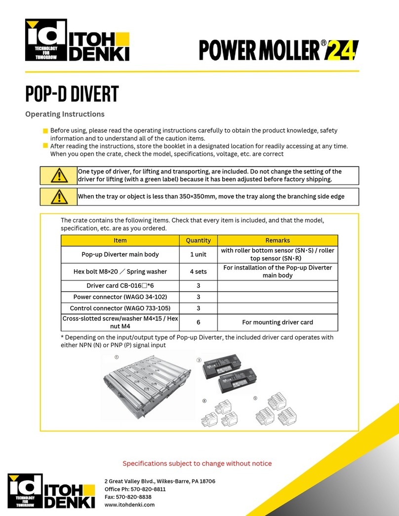
ITOH DENKI POWER MOLLER 24 Pop-D Divert User manual

ITOH DENKI
ITOH DENKI POWER MOLLER 24 F-RAT-U225 User manual

ITOH DENKI
ITOH DENKI F-RAT-S300 Series User manual

ITOH DENKI
ITOH DENKI F-RAT-NX75 User manual