GREER Company MicroGuard RCI 510 Programming manual

MicroGuard®
RCI 510
Rated Capacity Indicator System
Troubleshooting Manual


MICROGUARD RCI 510 TROUBLESHOOTING MANUAL i W450260D 03/10
TABLE OF CONTENTS
Introduction ..............................................................................................................................................................................1
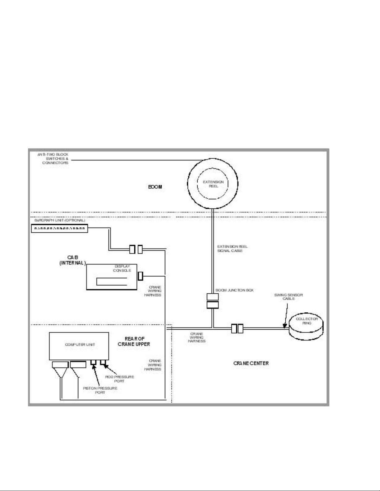
1.1 Overview and Preparation ...........................................................................................................................................2
2.1 System Self-Test ...............................................................................................................................................................3
2.2 Display Console Problems .....................................................................................................................................4
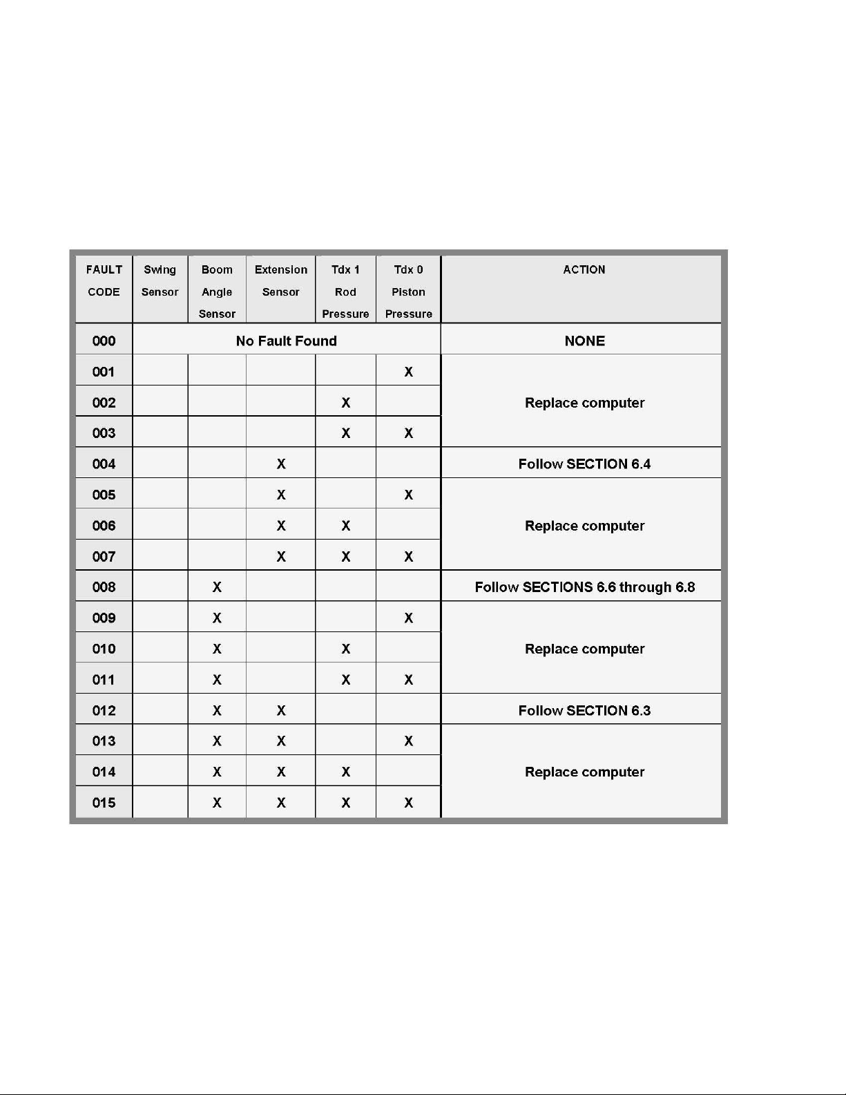
2.3 Fault Reporting and Fault Codes ........................................................................................................................5
2.3.1 Group “A” Fault Codes ...........................................................................................................................................6
2.3.2 Group “B” Fault Codes ..........................................................................................................................................8
2.3.3 Group “C” Fault Codes ..........................................................................................................................................9
2.3.4 Group “D” Fault Codes ....................................................................................................................................... 10
2.4 “No Fault Code” Problems .................................................................................................................................... 11
2.4.1 Anti Two-Block Alarm (A2B) ............................................................................................................................ 11
2.4.2 Displayed Load or Radius Errors .................................................................................................................... 12
3.1 Computer Unit Overview .......................................................................................................................................... 14
3.2 Computer Unit Layout .......................................................................................................................................... 15
3.3 Internal Status Indicators ................................................................................................................................... 17
3.4 The COMM Indicator ............................................................................................................................................ 18
3.5 Computer Unit Replaceable Part ..................................................................................................................... 19
3.5.1 Function Kickout Fuse (FUS1) ......................................................................................................................... 19
3.6 Pressure Sensors ..................................................................................................................................................... 20
3.7 Replacing the Computer Unit ........................................................................................................................... 21
4.1 Display Console Overview ........................................................................................................................................ 22
4.2 Display Console Models ....................................................................................................................................... 22
4.3 Checking the Display Console ........................................................................................................................... 22
4.3.1 Reading the LCD ................................................................................................................................................. 22
4.3.2 Unresponsive Buttons ....................................................................................................................................... 23
4.3.3 Connectors ............................................................................................................................................................ 23
4.3.4 Horn ......................................................................................................................................................................... 23
4.3.5 Moisture ................................................................................................................................................................ 23
4.4 Replacing the Display Console .......................................................................................................................... 24
5.1 Remote Bar Graph Overview ..................................................................................................................................... 25
5.2 Checking the Remote Bar Graph ..................................................................................................................... 25
5.2.1 Lamps ..................................................................................................................................................................... 25
5.2.2 Brightness Control ............................................................................................................................................. 25
5.2.3 Cable and Connector ....................................................................................................................................... 26

MICROGUARD RCI 510 TROUBLESHOOTING MANUAL ii W450260D 03/10
5.2.4 Moisture ................................................................................................................................................................ 26
5.3 Remote Bar Graph Replacement ..................................................................................................................... 26
6.0 Entering the Calibration Mode ................................................................................................................................. 27
6.1 Extension Reel Overview .................................................................................................................................... 28
6.2 Checking the Reel-O Cable Layering .......................................................................................................... 29
6.3 Checking the Extension Sensor Drive Voltage ........................................................................................... 30
6.4 Checking the Boom Extension Sensor Voltage .......................................................................................... 30
6.5 Extension Sensor Setup ...................................................................................................................................... 31
6.5.1 Physical Zero ....................................................................................................................................................... 31
6.5.2 Zero Calibration .................................................................................................................................................. 31
6.5.3 Span Calibration ................................................................................................................................................. 32
6.6 Checking the Angle Sensor Pendulum .......................................................................................................... 33
6.7 Checking the Angle Sensor Drive Voltage ................................................................................................... 34
6.8 Checking the Angle Sensor Voltage ............................................................................................................... 34
6.9 Angle Sensor Setup .............................................................................................................................................. 30
6.9.1 Physical Zero ....................................................................................................................................................... 30
6.9.2 Zero Calibration .................................................................................................................................................. 36
6.9.3 Span Calibration ................................................................................................................................................. 36
6.10 Extension Reel Replaceable Parts ................................................................................................................. 37
6.10.1 Extension Reel-O Cable .............................................................................................................................. 37
6.10.2 Slip Ring Assembly ......................................................................................................................................... 39
6.10.3 Sensor Baseplate Assembly ......................................................................................................................... 41
6.10.4 Signal Cable Assembly .................................................................................................................................. 43
7.1 Anti Two-Block Function Overview ......................................................................................................................... 45
7.2 Checking the Extension Reel-O Cable ....................................................................................................... 47
8.0 Power, Kickout & Boom Mode Outputs ................................................................................................................. 48
9.1 Swing Sensor Overview .............................................................................................................................................. 49
9.2 Checking the Swing Sensor Drive Voltage ................................................................................................... 50
9.3 Checking the Swing Sensor Output Voltage ............................................................................................... 50
9.4 Checking the Swing Sensor Resistance ........................................................................................................ 50
9.5 Swing Sensor Setup and Checks ..................................................................................................................... 51
9.5.1 Checking and Setting Zero ............................................................................................................................ 51
9.5.2 Checking and Setting Direction ................................................................................................................... 51

MICROGUARD RCI 510 TROUBLESHOOTING MANUAL 1 W450260D 03/10
Introduction
The Greer Company is dedicated to the design and manufacture of electronic parts created to aid in
crane operation and in the protection of crane operators and associated personnel. The following
manual has been developed to assist in helping Service Personnel to understand, locate, and identify
problems that may arise during the operation of the MicroGuard® RCI-510 Rated Capacity Limiter
System. Do not use this system in place of an operator who is knowledgeable in safety guidelines,
crane capacity information, and the crane manufacturer’s specications. Use of calibration routines
without consultation with the Greer Company invalidates the warranty.
Where to go For Help
When eld repairs cannot be made without replacement of a part, or when troubleshooting advice is
needed, one of the following support numbers should be called:
TEREX
Waverly, Iowa
Telephone:(319) 352-3920
FAX: (319) 352-9378
Greer Company
Service: Jenks, OK
Telephone:(918) 298-8300
FAX: (918) 298-8301
Information provided to support personnel must be accurate and complete. Have your crane Model
Number and Serial Number ready. Carefully describe the problem, noting any unusual System
responses that may help us to quickly and eectively solve your problem.

MICROGUARD RCI 510 TROUBLESHOOTING MANUAL 2 W450260D 03/10
1.1 Overview & Preparation
This Troubleshooting Manual for the MicroGuard® RCI-510 Rated Capacity Limiter System,
manufactured by the Greer Company provides information and methods for isolating problems that
may arise during operation of the System. Some of these problems can be corrected in the eld.
Other problems may require replacement of parts or a return of a part to the factory for servicing.
Service personnel should have prior training and experience in the procedure for operation and
setup of this System.
The procedures in this manual, where possible, are based on crane operation and function. A basic
tool kit consisting of wrenches and screwdrivers (at and Phillips’ blades) will be required to remove
covers and units for inspection. A digital multimeter (DMM) may be required. The DMM must be
capable of measuring DC voltage with a range of 0 volts to ± 50 volts and resolution of 0.1 volts.
Resistance range is 0 ohms to 2 megohms. Low cost analog meters are not appropriate since the
input impedance of these meters can give false readings.
FIGURE 1.1
SYSTEM SCHEMATIC OVERVIEW

MICROGUARD RCI 510 TROUBLESHOOTING MANUAL 3 W450260D 03/10
2.1 SYSTEM SELF-TEST
When the power is turned on or when the ”TEST” button is pressed during operation, the computer
and operator’s display console perform a “SELF-TEST,” which, as far as is possible, veries that the
computer, display console, cables, and all remote sensors are working properly.
During SELF-TEST, all display functions are activated, allowing the operator to check whether or not
all indicators are functional.
NOTE: IT IS IMPORTANT THAT THE INDICATIONS SHOWN DURING THE SELF-TEST ARE RECOGNIZED
AND FULLY UNDERSTOOD BY THE OPERATOR IN ORDER TO AID IN CORRECTLY DETERMINING
COMPUTER AND DISPLAY COMMUNICATION PROBLEMS.
For six seconds following “power on” or activation of the TEST button (T), the display will show the
following indications:
• All display segments of the bar graph display (B) will be black (ON).
• All display segments of the load, angle, radius, length, and rated capacity windows will be black
(ON), showing “i88.8” or “888,800” for load and capacity.
• All green conguration lamps will be illuminated.
• The red LED indicators for overload and Anti Two-Block will be illuminated.
• The yellow LED indicator for pre-warning will be illuminated.
• The audible alarm will sound in the crane cab.
• The display will now show the crane model/chart number and the units of measurement along
with the message: “SELF-TEST IN PROGRESS.”
FIGURE 2.1
THE DISPLAY CONSOLE

MICROGUARD RCI 510 TROUBLESHOOTING MANUAL 4 W450260D 03/10
The display will then freeze with the message:
“READ/ UNDERSTAND THE FOLLOWING ASMA MANUAL. ANST/ANSI B30-5
All green OSHA REGULATIONS, OPERATOR’S MANUAL.”
The display segments will be set to (----) and the red and amber and ATB lamps will be on. All green
conguration lamps will be illuminated.
IF ANY OF THE ABOVE INDICATIONS DO NOT OCCUR, CONTINUE TO SECTION 2.2
DISPLAY CONSOLE PROBLEMS.
2.2 DISPLAY CONSOLE PROBLEMS
DISPLAY CONSOLE PROBLEMS are dicult to isolate because of the interaction between the display
console and the computer unit. Failure of either unit, or interconnection of the two units, causes
malfunction of display console indications. No “FAULT” diagnoses of other system problems can
be carried out without the proper function of the display console and it’s communication with the
computer unit.
To solve problems using display console indications, carefully observe the display console at “power
on” and through self-test. Next, use the following chart to help decide the course of action.
PROBLEM ACTION
There are no display console indications at all
when power is turned on. All displays remain
blank and no lights are illuminated.
Refer to SECTION 3.3.
The load, angle, radius, length, and rated
capacity display windows do not show
“I88.8” or the bar graph display window has
missing black segments during the self-test.
Replace display console.
The red or yellow indicator lights do not
illuminate during self-test.
Replace display console.
The display console does not do the self-test.
No words or logical numbers ever appear
after power is turned on. The displays look
jumbled, with lots of missing segments.
Replace display console.
The display console lights are lit. Load, angle,
radius, length and rated capacity show “I88.8”
or 888,800 for load and capacity, but the
display window shows only a message: "Bad
communications with main computer."
Display console is OK.
Check connectors at rear of display console.
Refer to SECTION 3.4.

MICROGUARD RCI 510 TROUBLESHOOTING MANUAL 5 W450260D 03/10
2.3 FAULT REPORTING AND FAULT CODES
SYSTEM FAULT CODES provide one of the most important ways to quickly locate and assess problems
in the MicroGuard®System. Please review this section carefully.
Each time the system is turned on, it goes through a self-testing process lasting six seconds that
automatically detects most faults in the system. During normal operation, a self-test can be initiated
at any time by pressing the TEST button on the display console.
Many fault conditions are detected without a system self-test.
Faults detected in the system during the self-test, are indicated on the display console in the
following ways:
The RED OVERLOAD LAMP will illuminate.
The AUDIBLE ALARM will sound.
“WARNING SYSTEM FAULT!” will be displayed at the bottom of the text window.
Fault codes may be displayed on the display console. To view the codes, press and hold the TEST
button and wait for the system to complete the self-test. Do not release the TEST button. Fault codes
will now be displayed at the bottom of the text window for as long as the TEST button is held down.
FAULTS A000 B0 C00 D00
FIGURE 2.3
FAULT CODE DISPLAY SHOWN IN LOWER PORTION OF TEXT DISPLAY WINDOW
There are four groups of FAULT CODES: A,B,C & D. The function of these groups and a complete listing
of each code is provided on the following pages.
NOTE: ALWAYS INVESTIGATE FAULTS IN THE “B” AND “C” GROUPS BEFORE CONTINUING
WITH “A” AND FINALLY “D” GROUP FAULTS.

MICROGUARD RCI 510 TROUBLESHOOTING MANUAL 6 W450260D 03/10
2.3.1 GROUP “A” FAULT CODES
GROUP “A” FAULT CODES REPRESENT FAULTS DETECTED FOR ANALOG SENSORS.
NOTE: CHECK AND REPAIR “B” AND “C” GROUP FAULTS BEFORE PROCEEDING WITH GROUP “A” FAULT
FINDING SENSORS,
The following chart details all the available codes in the left column and the actions to take
in the right column.

MICROGUARD RCI 510 TROUBLESHOOTING MANUAL 7 W450260D 03/10
FAULT
CODE
Swing
Sensor
Boom
Angle
Sensor
Extension
Sensor
Tdx 1
Rod
Pressure
Tdx 0
Piston
Pressure
ACTION
016 X Follow SECTION 9
017 X X
018 X X Replace computer
019 X X X
020 X X Follow SECTIONS 6.3, 6.4 & 9
021 X X X
022 X X X Replace computer
023 X X X X
024 X X Follow SECTIONS 6.7, 6.8 & 9
025 X X X
026 X X X Replace computer
027 X X X X
028 X X X Follow SECTIONS 6.3, 6.4, 6.7, 6.8 & 9
029 X X X X Replace computer
030 X X X X
031 X X X X X Follow SECTIONS 6.3, 6.4, 6.7, 6.8 & 9
032 &
Higher
Internal Temperature Sensor Fault
Replace Computer Unit
2.3.1 GROUP “A” FAULT CODES continued

MICROGUARD RCI 510 TROUBLESHOOTING MANUAL 8 W450260D 03/10
2.3.2 GROUP “B” FAULT CODES
GROUP “B” FAULT CODES REPRESENT FAULTS DETECTED FOR INTERNAL ANALOG
FUNCTIONS AND POWER FEEDS TO THE FUNCTION KICKOUT AND ANTI-TWO BLOCK SWITCHES.
The following chart details all of the available codes in the left column and the actions to take
in the right column.
FAULT
CODE
FKO
POWER
FEED
A2B
POWER
FEED
DISPLAY
CONSOLE
ADC 2
INTERNAL
FAULT
ADC 1
INTERNAL
FAULT
ACTION
000 No Fault Found NONE
001 X
002
X
003
X
X
004 X Replace computer
005 X X
006 X X
007 X X X
008 X See SECTION 7
009 X X
010 X X
011
X
X
X
012 X X Replace computer
013 X X X
014
X
X
X
015
X
X
X
X
016 X Check crane circuit breakers, then
See SECTION 3.5.1
017 X X
018
X
X
019
X
X
X
020
X
X
Replace computer
021 X X X
022
X
X
X
023 X X X X
024 X X Check crane circuit breakers, then
See SECTION 3.5.1
025 X X X
026
X
X
X
027
X
X
X
X
028 X X X Replace computer
029 X X X X
030 X X X X
031 X X X X X

MICROGUARD RCI 510 TROUBLESHOOTING MANUAL 9 W450260D 03/10
2.3.3 GROUP “C” FAULT CODES
GROUP “C” FAULT CODES REPRESENT FAULTS DETECTED FOR
INTERNAL COMPUTER MEMORIES.
The following chart details all the available codes in the left column and the actions to take in the
right column.
FAULT
CODE
SERIAL
EEPROM
CRANE
DATA
RAM DUTY
DATA
PROGRAM ACTION
000 No Fault Found NONE
001
X
002 X Replace system chip
003 X X Follow SECTION 3.5.2
004 X Replace computer
005
X
X
006 X X Replace system chip
007 X X X Follow SECTION 3.5.2
008 X Reset crane data
009
X
X
010
X
X
Replace system chip
011 X X X Follow SECTION 3.5.2
012 X X Replace computer
013
X
X
X
014
X
X
X
Replace system chip
015 X X X X Follow SECTION 3.5.2
016 X Reselect crane
setup/configuration
Replace computer, if not resolved
017
X
X
018
X
X
Replace system chip
019 X X X Follow SECTION 3.5.2
020 X X Replace computer
021
X
X
X
022
X
X
X
Replace system chip
023 X X X X Follow SECTION 3.5.2
024 X X Reselect crane
setup/configuration
Reset crane data
Replace computer, if not resolved
025
X
X
X
026 X X X Replace system chip
027 X X X X Follow SECTION 3.5.2
028
X
X
X
029
X
X
X
X
Replace computer
030
X
X
X
X
031 X X X X X

MICROGUARD RCI 510 TROUBLESHOOTING MANUAL 10 W450260D 03/10
2.3.4 GROUP “D” FAULT CODES
GROUP “D” FAULT CODES REPRESENT FAULTS DETECTED
FOR CAPACITY CHART SELECTION.
The following chart details all the available codes in the left column and the actions to take in the
right column.
FAULT
CODE
WRONG
SWING
AREA
WRONG
BOOM
LENGTH
CHART
NOT
FOUND
ACTION
000 No Fault Found NONE
001 X Re-select CRANE SETUP.
Check other sensor faults first.
002 X Boom length is out of range for selected chart.
Check crane setup, boom length and extension
003 X X Re-select CRANE SETUP.
Check other sensor faults first.
004 X Swing to correct working area to select chart.
Check swing sensor zero position.
Follow SECTION 9.5
005 X X Swing to correct working area to select chart.
Check swing sensor zero position.
Follow SECTION 9.5
006 X X Re-select CRANE SETUP.
Check other sensor faults first.
007 X X X Re-select CRANE SETUP.
Check other sensor faults first.

MICROGUARD RCI 510 TROUBLESHOOTING MANUAL 11 W450260D 03/10
2.4 “NO FAULT CODE” PROBLEMS
THIS SECTION ADDRESSES THOSE PROBLEMS THAT MAY OCCUR AND ARE NOT REPORTED BY THE
COMPUTER FAULT CODE SYSTEM.
2.4.1 ANTI TWO-BLOCK ALARM (A2B)
This section gives direction to fault diagnosis of A2B alarm problems. For detailed information, sche-
matic, and voltages, refer to SECTION 7 - ANTI TWO-BLOCK FUNCTION.
PROBLEM:
• TheAntiTwo-BlockalarmiscontinuouslyON.Operatingtheswitchattheboomheaddoes
notdeactivatethealarm.
This problem suggests an open circuit between the computer A2B input and the A2B switch(es), or
an open circuit between the computer A2B feed and the A2B switch(es). Check extension reel-o
cable for damage. Make sure that the Two-Block switches are correctly connected. Check the slip-ring
and wiring inside the extension reel. Check the signal cable from the extension reel to the computer.
Check connectors.
PROBLEM:
• TheAntiTwo-BlockalarmiscontinuouslyOFF(safe).De-operatingtheswitchattheboom
head,byliftingtheA2Bweightdoesnotactivatethealarm.
This problem suggests a short circuit between the computer A2B input and the computer A2B feed
somewhere between the computer and the A2B switch(es). Check extension reel-o cable for dam-
age. Make sure that the Two-Block switches are correctly connected. Check the slip-ring and wiring
inside the extension reel. Check the signal cable from the reel to the computer. Check connectors.

MICROGUARD RCI 510 TROUBLESHOOTING MANUAL 12 W450260D 03/10
2.4.2 DISPLAYED LOAD OR RADIUS ERRORS
This section gives direction to fault diagnosis of load and radius errors as displayed on the display
console. Load or radius errors may give rise to early or late tripping of overload alarms. Accuracy
of load, radius, length, and angle is determined by the correct installation and maintenance of the
system sensors. Accuracy of load is governed by the radius accuracy, and the extension, angle, and
pressure sensors. Accuracy of radius (unloaded) is governed by the extension and angle sensors.
Before continuing, make sure that there are no system faults.
CHECK BOOM EXTENSION
1. First check that the boom is fully retracted.
2. Check that the extension reel-o cable is correctly layered as a single layer across the extension
reel surface. Any stacking of the cable will cause extension errors when the boom is fully retract-
ed, causing the System to exceed the 0.5 ft tolerance allowed by the computer for boom mode
selection. If the reel-o cable is stacking on the reel, see SECTION 6.2.
3. Check the zero of the extension sensor at the fully retracted boom position. Enter the Calibration
Mode and use the “SPAN” command. Select sensor No. 2 to view the extension value in feet. The
value of extension must be between -0.2 and +0.2, with the boom fully retracted. If the exten-
sion value is incorrect, follow the EXTENSION SENSOR SETUP procedure in SECTION 6.5. Fully
telescope the boom and check that the displayed boom length value matches the maximum
length of the boom. If the length value is incorrect, follow the EXTENSION SPAN procedure in
SECTION 6.5.3.
CHECK MAIN BOOM RADIUS
1. Fully retract the boom and make sure that the crane conguration is correctly set up.
NOTE: THE REQUIRED ACCURACY OF TAPED RADIUS MEASUREMENTS IS WITHIN 0.1 FEET. WHEN TAK-
ING RADIUS MEASUREMENTS ALWAYS USE A GOOD QUALITY TAPE THAT DOES NOT STRETCH. THE
TAPE SHOULD BE GRADUATED IN FEET AND TENTHS OF A FOOT. ALWAYS MEASURE BETWEEN THE
SWING CENTER OF THE CRANE AND THE HOOK LINE, USING A SINGLE PART OF LINE WITH THE CRANE
CENTERED OVER FRONT (ROUGH TERRAIN) OR CENTERED OVER REAR (TRUCK CRANE).
2. Boom up to about 45° and measure the radius. The measured radius must match the displayed
radius within +/- 0.2 ft. If it does not match, continue to the “CHECK BOOM ANGLE” procedure. If it
does match, continue to “CHECK PRESSURE SENSORS.”
3. Boom up to a high angle (at least 70°) and measure the angle with the inclinometer. Check that
the displayed angle matches the inclinometer reading within 0.2°. If the displayed angle is incor-
rect, follow the angle span calibration procedure in SECTION 6.9.3.

MICROGUARD RCI 510 TROUBLESHOOTING MANUAL 13 W450260D 03/10
CHECK BOOM ANGLE
1. Fully retract the boom.
NOTE: THE REQUIRED ACCURACY OF MEASURED ANGLES IS WITHIN 0.2°. WHEN TAKING BOOM
ANGLE MEASUREMENTS, ALWAYS USE A GOOD QUALITY INCLINOMETER. MANY INCLINOMETERS
ARE ONLY ACCURATE AT 0° (LEVEL). MAKE SURE THAT A RELIABLE POSITION ON THE TOP OF THE
BOOM IS USED TO MEASURE THE ANGLE AND THAT THE INCLINOMETER WILL PROVIDE AN ACCURATE
READING AT 0° (ZERO) AND AT 70°.
2. Using an inclinometer, set the boom to 0° (zero) and check that the displayed boom angle value is
0.0°. If the angle value is not 0.0°, follow SECTIONS 6.6, 6.9.1 and 6.9.2.
3. Boom up to a high angle (at least 70°) and measure the angle with the inclinometer. Check that
the displayed angle matches the inclinometer reading within 0.2°. If the displayed angle is incor-
rect, follow the angle span calibration procedure in SECTION 6.9.3.
CHECK PRESSURE SENSORS
The Pressure sensing system is factory calibrated, therefore pressure sensors may not be individually
replaced. Any serious problems will necessitate changing the entire computer unit.
1. Boom fully down until the boom hoist cylinder is fully retracted and on its stop.
2. Loosen the hydraulic connections to the pressure sensors to guarantee zero pressure is present
on the sensors.
3. Enter the CALIBRATION MODE and use the “PRESSURE MONITOR” command to view both sensor
pressures and nett pressure.
4. Check the PRESSURE values of both sensors. The PRESSURE values should be between -75 and
+ 75 PSI. If not, replace the computer unit.
5. Check the NETT pressure. This should be between -35 and +35 psi. If not, replace the computer
unit.
FIGURE 2.4.2
PRESSURE MONITOR

MICROGUARD RCI 510 TROUBLESHOOTING MANUAL 14 W450260D 03/10
3.1 COMPUTER UNIT OVERVIEW
The COMPUTER UNIT, shown in Figures 3.1 and 3.2, is the center of the System. The computer unit
provides all necessary functions to read the sensors, control computations, disconnect functions, and
communicate with the display console/internal bar graph.
The computer unit directly connects to the crane wiring harness via a 60-way bulkhead connector.
There are no wiring connections or screw terminals within the unit.
Contained within the unit, are two hydraulic pressure transducers required to sense pressure within
the boom hoist cylinder. These sensors, as well as the computer are factory pre-calibrated and, as
such, may not be separately replaced in the eld.
FIGURE 3.1
THE COMPUTER UNIT

MICROGUARD RCI 510 TROUBLESHOOTING MANUAL 16 W450260D 03/10
3.2 COMPUTER UNIT LAYOUT (Continued)
Other manuals for MicroGuard RCI 510
1
Table of contents
Other GREER Company Industrial Equipment manuals
Popular Industrial Equipment manuals by other brands

GSi
GSi PNEG-222 installation manual

Siemens
Siemens 5WG1 425-7AB72 Operating and mounting instructions

Telegärtner
Telegärtner NRT 1 EX G3 Mounting and installation instructions

Nexen
Nexen AIR CHAMP FC-605 user manual

PRECISETOOL
PRECISETOOL TS-01 instructions

Emerson
Emerson AVENTICS NL1 operating instructions

Allen-Bradley
Allen-Bradley ControlNet Coax Tap 1786-TPR installation instructions

Scanivalve
Scanivalve DSA5000 Operation and service manual

TERASAKI
TERASAKI T2DR25 instruction manual

JBL
JBL PRO FLORA TAIFUN SPIRAL 5 manual

Siemens
Siemens Simatic S7-400 Getting started

Siemens
Siemens SIMATIC IPC operating manual