Berker RolloTec 2911 User manual

1
825 307 01 06.2003
Bedienungsanleitung
Operating Instructions
Bedieningshandleiding
Mode d’emploi
RolloTec®
RolloTec®Standardeinsatz ohne
Neutralleiteranschluss
RolloTec®Flush-Mounted ‘Standard’ Insert
without Neutral Conductor
RolloTec® inbouw-inzetmoduul ‘Standard’
zonder nulleider-aansluiting
Insert ‘Standard’ RolloTec®encastrable
sans conducteur neutre
Best.Nr. 2911

3
2
Inhaltsverzeichnis
Inhaltsverzeichnis
1. Funktion ............................................................................................... 4
2. Kombinationsmöglichkeiten.................................................................. 6
3. Hinweise............................................................................................... 8
4. Prüfung der Eignung von Motoren ....................................................... 10
5. Anschluss und Montage....................................................................... 13
6. Installationshinweise bei der Verwendung von Sensoren .................... 14
7. Technische Daten................................................................................. 18
8. HGewährleistung.................................................................................. 19
D
Gefahrenhinweise
Achtung! Einbau und Montage elektrischer Geräte dürfen nur durch eine
Elektrofachkraft erfolgen.
Nur für den Anschluss eines Motors mit Endlagenschalter mit max. 1000W!
Bei Nichtbeachtung der Installationshinweise können Schäden am
Gerät, Brand oder andere Gefahren entstehen.
Die Jalousiesteuerung wurde für das automatische Betätigen von Fen-
ster-Jalousien und Fenster-Rollladen entwickelt.
Andere Anwendungen können Gefahren mit sich bringen, z.B. die Steue-
rung eines Rolltores. Diese Gefahren müssen vom Anwender durch
Einsatz zusätzlicher geeigneter Sicherheitsmaßnahmen (z.B. Licht-
schranken) ausgeschlossen werden.
Bitte lesen Sie vor Installation und Gebrauch des Gerätes diese Bedie-
nungsanleitung und geben Sie diese nach der Installation Ihrem Kunden!
D
Gefahrenhinweise

5
4
Funktion
Funktion
Achtung: Schließen Sie je Einsatz nur einen Motor mit
Endlagenschalter bis max. 1000W an.
Verwenden Sie keine Trennrelais.
Prüfen Sie unbedingt die Eignung des Motors wie in Kap. 4
beschrieben.
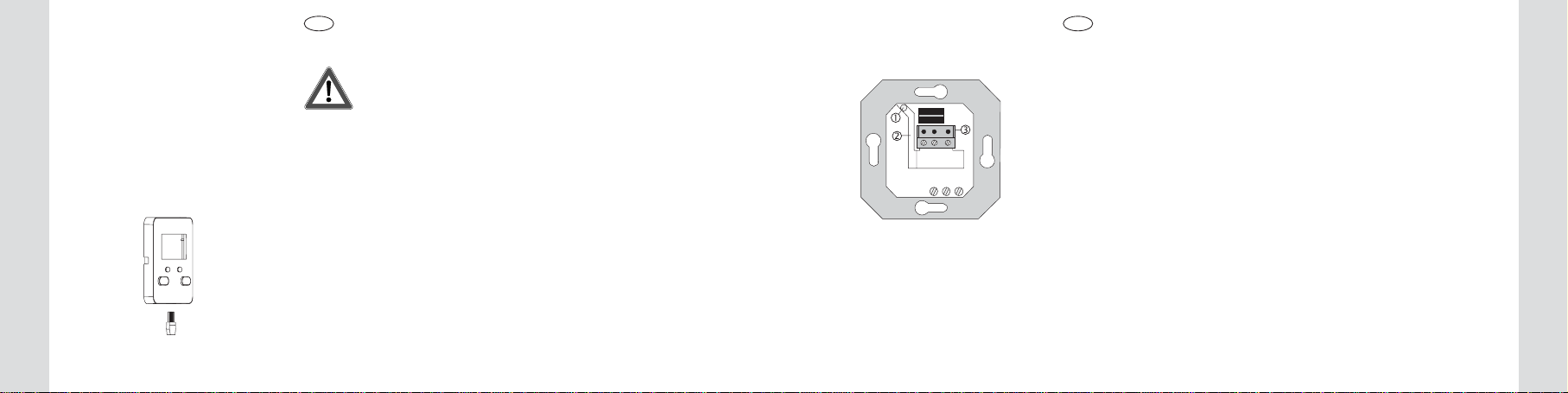
Der Einsatz verfügt über 3 Anschlussklemmen (1) und eine 6-polige Schnitt-
stelle (2) zur Kontaktierung des Aufsatzes.
Zusätzlich kann im Einsatz ein 3-poliger Klemmblock (3) eingelegt werden
(liegt dem Aufsatz mit Sensoranschluss bei).
An diesen Klemmblock können bei Verwendung eines Aufsatzes mit Sensor-
auswertung je nach Typ verschiedene Sensoren angeschlossen werden:
•Sonnenschutz-/Dämmerungssensor (Best.Nr: 0169)
•Glasbruchsensor (Best.Nr: 0170)
1. Funktion
Der RolloTec®Standardeinsatz ohne Neutralleiteranschluss wird in Installatio-
nen ohne Neutralleiter (N) verwendet.
Der mechanische Jalousieschalter kann daher direkt durch eine komfortable
Steuerung mit dem RolloTec®Standardeinsatz ohne Neutralleiteranschluss
ersetzt werden.
Der RolloTec®Standardeinsatz ohne Neutralleiteranschluss ist eine Kompo-
nente des Jalousiesteuerungs-Systems und wird in Verbindung mit Aufsätzen
aus Jalousiesteuerungssystem in einer Gerätedose nach DIN 49073 (Emp-
fehlung: tiefe Dose) montiert.
Es ergibt sich somit die Möglichkeit, durch Austausch des Aufsatzes, eine
manuelle Bedienung, eine Komfortbedienung über Funk-Fernbedienung oder
eine vollautomatische Zeitsteuerung zu realisieren.
Der Einsatz verfügt über 2 leistungsstarke Relaiskontakte, die mechanisch
gegeneinander verriegelt sind. Eine gleichzeitige Ansteuerung des ange-
schlossenen Jalousiemotors in beiden Laufrichtungen ist dadurch ausge-
schlossen.
D D

7
6
Kombinationsmöglichkeiten
Kombinationsmöglichkeiten
2. Kombinationsmöglichkeiten
Je nach verwendetem Aufsatz werden z.Z. folgende unterschiedliche
Funktionalitäten erreicht:
RolloTec®Taste (Best Nr. 1750 .., 1751 ..)
Verwendung als manuell bedienbarer Taster.
(siehe Bedienungsanleitung ‘RolloTec®Taste’).
RolloTec®Funk-Taste (Best Nr.1758 .., 1759 ..)
Verwendung als manuell und per Funk-Fernsteuerung bedienbarer Taster.
(siehe Bedienungsanleitung ‘RolloTec®Funk-Taste’).
RolloTec®Speicher-Taste (Best Nr. 1756 .., 1757 .. )
Verwendung als manuell bedienbarer Taster mit zusätzlicher automatischer
Steuerung.
Dieser Aufsatz ermöglicht durch die Speichermöglichkeit einer Auffahr- und
einer Abfahrzeit, eine einfache individuelle Programmierung.
Die beiden gespeicherten Jalousiefahrzeiten werden im 24-Stunden-Rhythmus
wiederholt. (siehe Bedienungsanleitung ’RolloTec®Speicher-Taste’)
Zusätzlich können bei Verwendung der oben genannten Aufsatzvarianten mit
Sensorauswertung die Funktionen Glasbruch-Alarm und Sonnenschutz reali-
siert werden.
D D
L
L
L
RolloTec®Aufsatzmodul Schaltuhr oder RolloTec®Aufsatzmodul Schalt-
uhr Easy
Verwendung als automatische Steuerung mit programmierbaren Schaltzeiten.
Siehe dazu Bedienungsanleitungen:
RolloTec®Aufsatzmodul Schaltuhr Easy (Best Nr.1762 ..) und RolloTec®Auf-
satzmodul Schaltuhr (Best Nr. 1754 .., 1755 .. )
Zusätzlich können beiVerwendung der Komfort-Version mit Sensorauswertung
folgende Funktionen realisiert werden:
•Glasbruch-Alarm
•Sonnenschutzfunktion
•Dämmerungsfunktion
L
Datum
Uhrzeit
Mode Set
Prog Zufall Astro
WS
Mo
Di
Mi
Do
Fr
Sa
So
A
B
C

9
8
Hinweise
Hinweise
D D
3. Hinweise
Verwenden Sie ausschließlich Jalousie- bzw. Rollladen-Motoren mit mecha-
nischen oder elektronischen Endlagenschaltern.
Prüfen Sie die Eignung des Rollladen- oder Jalousiemotors vor der
Verwendung des RolloTec®Standardeinsatz ohne Neutralleiteranschluss
entsprechend der Anweisung in Kapitel 4.
Keine Trennrelais verwenden, die Jalousiesteuerung kann sich dann nicht
über die Motorwicklung versorgen. Fehlfunktion!
Beachten Sie die Hinweise der Motorenhersteller bezüglich Umschaltzeit,
max. Einschaltdauer (ED).
Nehmen Sie den RolloTec®Standardeinsatz ohne Neutralleiteranschluss nur
in Verbindung mit einem der folgenden Aufsätzen in Betrieb:
•RolloTec®Taste
•RolloTec®Funk-Taste
•RolloTec®Speicher-Taste
•RolloTec®Aufsatzmodul Schaltuhr Easy
•RolloTec®Aufsatzmodul Schaltuhr
Durch die elektronische Verriegelung des Aufsatzes wird eine minimale Um-
schaltzeit bei Dauerlauf von ca. 1 Sekunde realisiert.
Entsteht der Wunsch einen Jalousiemotor zusätzlich zur Bedienung vor Ort
auch noch von übergeordneten Stellen (z.B. Zentralsteuerung) zu schalten,
muss der RolloTec®Einsatz (Best.Nr. 2975) verwendet werden, der über
Nebenstelleneingänge verfügt. (Neutral-Leiter erforderlich).
Sollte die Sensorleitung verlängert werden müssen, wählen Sie eine geeig-
nete Sensorleitung. Empfehlung: J-Y(ST)Y 2x2x0,6 mm.
11
10
Prüfung der Motoren
Prüfung der Motoren
D D
4. Prüfung der Eignung von Motoren
Häufig ist nicht bekannt, ob ein Motor mit mechanischen oder mit elektroni-
schen Endlagenschaltern eingesetzt ist.
Prüfen Sie daher zunächst die Eignung des Motors.
Einige Motoren mit mechanischen Endlagenschaltern bauen im
Betrieb eine hohe Motorspannung auf, die den RolloTec®Standard
einsatz ohne Neutralleiteranschluss zerstören könnte. Die Prüfung
wird daher mit einem handelsüblichen mechanischen Jalousieschalter
(möglicherweise noch installiert) und nicht mit dem RolloTec®
Standardeinsatz ohne Neutralleiteranschluss durchgeführt.
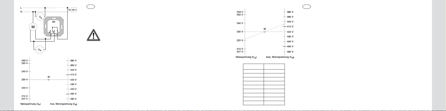
Führen Sie folgende Messung mit einem Voltmeter durch:
•Messen Sie die momentane Netzspannung UN.
•Suchen Sie auf der linken Seite des nebenstehenden Diagramms die
gemessene Netzspannung.
•Verbinden Sie den gefundenen Punkt über den Mittelpunkt M bis zur
rechten Achse durch eine Gerade. Der Schnittpunkt auf der rechten Achse
gibt die max. zulässige Motorspannung UMan.
•Messen Sie nun die Motorspannung UMin der Auf- und in der Abrichtung
am installierten handelsüblichen mechanischen Jalousieschalter. Der zuvor
ermittelte Maximalwert darf bei beiden Messungen nicht überschritten werden.
Beispiel-Diagramm:
Die gemessene Netzspannung UNbeträgt 221 V.Verbinden Sie den Wert 221
V auf der linken Achse im Diagramm durch den Mittelpunkt (M) zur rechten
Achse mit der Motorspannung UM. Sie erhalten eine max. zulässige Motor-
spannung von 404 V.
Die in Auf- und Abrichtung gemessenen Motorspannungen müssen daher
unter 404 V liegen.
Näherungsweise können die typ. maximalen Motorspannungen UMin Abhän-
gigkeit der Netzspannung UNnebenstehender Tabelle entnommen werden.
Unmax. Um
207 V 380 V
215 V 393 V
220 V 403 V
225 V 412 V
230 V 420 V
235 V 429 V
240 V 438 V
245 V 447 V
253 V 460 V
Beispiel

13
12
Anschluss und Montage
Prüfung der Motoren
D D
Motor mit elektronischen Endlagenschaltern
Wenn Gewissheit besteht, dass ein Motor mit elektronischen Endlagenschaltern
verwendet wird, kann die zuvor beschriebene Messung entfallen.
Der Einsatz kann durch Motoren mit elektronischen Endlagenschaltern bei
bestimmungsgemäßen Gebrauch nicht zerstört werden.
Prüfen Sie in diesem Fall die allgemeine Funktion des Motors in Kombination
mit dem RolloTec®Standardeinsatz ohne Neutralleiteranschluss wie folgt:
•Installieren Sie den RolloTec®Standardeinsatz ohne Neutralleiteranschluss
wie in Kap. 5 beschrieben.
•Stecken Sie einen Jalousie-Aufsatz auf.
•Testen Sie die Funktion der Jalousiesteuerung durch Probeläufe des ange-
schlossenen Motors
5. Anschluss und Montage
Der Anschluss des RolloTec®Standardeinsatz ohne Neutralleiteranschluss
erfolgt gemäß nebenstehendem Bild.
Montieren Sie den RolloTec®Standardeinsatz ohne Neutralleiteranschluss
(1) in eine Gerätedose nach DIN 49073 (Empfehlung: tiefe Dose).
Die Anschlussklemmen des Einsatzes müssen dabei unten liegen.
Stecken Sie den Aufsatz (2) zusammen mit dem Rahmen (3) auf den Einsatz auf.
Die elektrische Kontaktierung erfolgt über den Stecker (4).
Die zusätzlichen Steckkontakte (5) bei Aufsätzen mit Sensoranschluss, wer-
den beim Aufstecken mit Hilfe des im Einsatz eingelegten 3-poligen Klemm-
blocks automatisch kontaktiert.

15
14
Verwendung von Sensoren
Verwendung von Sensoren
D D
6.Installationshinweise bei der Verwendung von Sensoren
Wichtig: Die Sensorleitung führt Schutzkleinspannung (SELV).
Installations-Vorschriften nach VDE 0100 beachten.
Je nach Montage (UP oder AP) und je nach verwendeten Aufsatz, unter-
scheidet sich die Installation der Sensoren.
Die Sensorleitung ist werksmäßig mit einem Stecker ausgestattet.
Direktanschluss der Sensorleitung am Aufsatz
Verfügt der Aufsatz über eine Steckerbuchse, erfolgt der Anschluss der Sen-
soren mit Hilfe des Steckers an der Sensorleitung.
Der Stecker ist codiert und kann nur in einer Position gesteckt werden.(siehe
Bedienungsanleitungen der Aufsätze)
UP-Verlegung der Sensorleitung
Die Verlegung der Sensorleitung erfolgt hier über einen Leitungskanal im
Einsatz.
•Schneiden Sie den Stecker der Sensorleitung ab.
•Führen Sie die Sensorleitung durch den Isolierschlauch (liegt den Aufsätzen
mit Sensorauswertung bei).
•Stecken Sie die Leitung mit dem Isolierschlauch durch die Bohrung (1) des
Einsatzes.
Der Isolierschlauch muss die Sensorleitung im Installationsraum der UP-
Dose bis in den Leitungskanal (2) vollständig umschließen.
•Führen Sie die Leitung mit dem Isolierschlauch durch den Kanal (2) bis
zum Klemmblock (3).
Die Leitung muss präzise im Kanal liegen und darf keine Schlaufen zum
230 V Anschlussraum bilden.
•Legen Sie den Klemmblock (liegt den Aufsätzen mit Sensorauswertung
bei) wie im Bild gezeigt in den Einsatz ein (Schraubklemmen unten).

17
16
Verwendung von Sensoren
Verwendung von Sensoren
D D
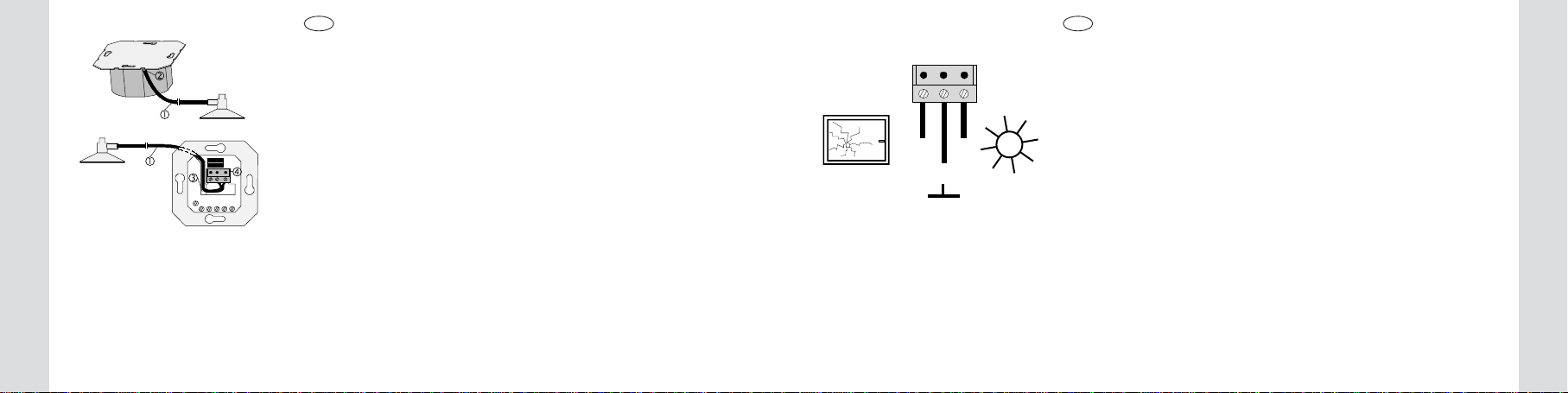
AP-Verlegung der Sensorleitung,Version 1
Anschluss erfolgt über Leitungskanal im Einsatz.
•Führen Sie die Sensorleitung (1) hinter der Tragplatte (zwischen Wand und
Tragplatte) durch die Öffnung (2) in den Leitungskanal (3) des Einsatzes.
•Führen Sie die Leitung direkt durch den Leitungskanal zum Klemmblock
(4). Die Leitung muss präzise im Leitungskanal liegen und darf keine
Schlaufen zum 230 V Anschlussraum bilden.
Anschluss an den Klemmblock im Einsatz:
Schließen Sie die Sensorleitungen nach nebenstehendem Bild an.
Die Schraubklemmen des Klemmblocks sind dabei unten.
Links: Signalleitung Glasbruchsensor
Mitte: Masse
Rechts: Signalleitung Sonnen-/Dämmerungssensor
Kennzeichnung der Leitungsadern:
Sensoren:
‘Masse’= grau gekennzeichnet
Adapter und Verlängerungsleitung:
‘Sonne’= grau gekennzeichnet
‘Masse’= mittlere Leitung
Sollen Sonnen-/ Dämmerungssensor und Glasbruchsensor gleichzeitig be-
trieben werden, Adapter verwenden (separat zu bestellen).
Schließen Sie den Adapter direkt am Aufsatz mit Hilfe des Steckers oder am
Einsatz über den 3poligen Klemmblock an (Stecker abgeschnitten).
Der Adapter verfügt über 2 Buchsen zum Anschluss der Sensorstecker.

19
18
Technische Daten
7.Technische Daten
Nennspannung : AC 230 V ~, 50 Hz
N-Leiter nicht erforderlich
Schaltleistung : max. 1 Motor 1000 W
Relaisausgang : 2 potentialbehaftete Schließer
(gegeneinander verriegelt)
Impulsdauer
RolloTec®Taste : 2 Minuten
RolloTec®Speicher-Taste : 2 Minuten
RolloTec®Funk-Taste : 2 Minuten
RolloTec®Aufsatzmodul Schaltuhr Easy: 2 Minuten
RolloTec®Aufsatzmodul Schaltuhr : Standardwert 2 Minuten
gelernt 1 Sekunde - 12 Minuten
Umschaltzeit bei Dauerlauf : min. 1 Sekunde (elektronische
Verriegelung durch Aufsatz)
Anschlussklemmen : Schraubklemmen für max. 2,5 mm²
oder 2 x 1,5 mm²
Leitungsschutzschalter : max. 16 A
D D
Berker GmbH & Co. KG
Abt. Service Center
Klagebach 38
D-58579 Schalksmühle
Telefon: 0 23 55 / 90 5-0
Telefax: 0 23 55 / 90 5-111
Gewährleistung
8. Gewährleistung
Wir leisten Gewähr im Rahmen der gesetzlichen Bestimmungen.
Bitte schicken Sie das Gerät portofrei mit einer Fehlerbeschreibung an
unsere zentrale Kundendienststelle:

21
20
Contents
GB GB
Contents
1. Function ............................................................................................... 22
2. Equipment combinations ...................................................................... 24
3. Instructions........................................................................................... 26
4. Checking the motors for suitability ....................................................... 28
5. Connection and fitting .......................................................................... 31
6. Installation with sensors ....................................................................... 32
7. Technical data ...................................................................................... 36
8. Acceptance of guarantee ..................................................................... 37
Safety instructions
Attention: Electrical equipment must be installed and fitted by qualified
electricians only.
Only for connection of a motor with limit switches and a power
consumption of max. 1000W. Non-observance of the fitting instructions
may damage the device and cause fire or other hazards.
The blind/shutter control is designed for the automatic operation of
window blinds and shutters.
Any other use as, for instance, the operation of roller-shutter gates may
involve hazards. These risks must be excluded by the user by providing
supplementary and suitable safety devices (e.g. light barriers).
Please read the operating instructions before installing and using the
device and hand them over to your customer after the installation!
Safety instructions

23
22
Function
Function
GB GB
The insert has 3 connecting terminals (1) and a 6-pole interface connector (2)
for connection of the attachment.
In addition, a 3-pole terminal block (3) can be placed into the insert (supplied
with inserts with sensor input).
This terminal block can be used to connect different sensors to the insert
when attachments with sensor input are installed:
•Sun protection / twilight sensor (order no. 0169)
•Glass breakage sensor (order no. 0170)
1. Function
The RolloTec®‘Standard’ insert without neutral conductor is used in electrical
installations without neutral conductor (N).
The existing mechanical shutter switch can therefore be replaced directly by a
comfortable control unit with the RolloTec®‘Standard’insert without neutral conductor.
The RolloTec®‘Standard’ insert without neutral conductor is a component of the
RolloTec®System and is used in conjunction with attachments of the RolloTec®
System in a mounting box acc. to DIN 49073 (deep box recommended).
By replacing the attachment it is therefore possible to realize systems with
manual operation, comfortable operation by radio remote control or timer-
controlled fully automatic operation.
The insert is equipped with two mechanically interlocked relay power contacts.
The simultaneous activation of both moving directions of the shutter motor
connected is thus excluded.
Attention: Connect only one motor with limit switches and a
power consumption of 1000 W max. to each insert.
Do not use isolating relays.
It is absolutely necessary to check the motor for suitability as
described in chapter 4.

25
24
Equipment combinations
Equipment combinations
GB GB
2. Equipment combinations
Depending on the attachment used, the following functions can be implemented:
RolloTec® pushbuttonattachment (order no. 1750 .., 1751 ..)
Pushbutton for manual operation.
(see ‘RolloTec® pushbutton’ operating instructions).
RolloTec®radio-control pushbutton attachment (order no. 1758 .., 1759 ..)
Pushbutton for manual and radio remote-control operation (see ‘RolloTec®
radio-control pushbutton’ operating instructions).
RolloTec®memory pushbutton attachment (order no. 1756 .., 1757 .. )
Pushbutton for manual operation with additional automatic control.
With its memory function for an UP and a DOWN movement, this attachment
permits simple and individual programming.
Both shutter movement times are repeated once every 24 hours (see ‘RolloTec®
memory pushbutton’ operating instructions)
If the above attachments are used in the versions with sensor input, the glass
breakage alarm and sun protection functions can also be implemented.
L
L
L
RolloTec®clock timer or clock timer ‘Easy’ attachment
Timer for automatic control with programmable switching times.
See also the operating instructions of:
RolloTec®clock timer (order no. 1762 ..) and RolloTec®clock timer ‘Easy’
(order no. 1754 .., 1755 .. )
When the versions with sensor input are used, the following functions are
available in addition:
•glass breakage alarm
•sun protection function
•twilight function
L
Datum
Uhrzeit
Mode Set
Prog Zufall Astro
WS
Mo
Di
Mi
Do
Fr
Sa
So
A
B
C
27
26
Instructions
Instructions
GB GB
3. Instructions
Use blind/shutter motors with mechanical or electronic limit switches only.
Check the blind/shutter motor for suitability in compliance with the
instructions set out in chapter 4 before using it in conjunction with the
RolloTec®‘Standard’ insert without neutral conductor.
Do not use isolating relays. With such relays, the blind/shutter control has no
power supply through the motor winding. Risk of malfunction.
Observe the instructions of the motor manufacturers concerning the switch-
over time and the maximum load factor (c.d.f.)
The RolloTec®‘Standard’ insert without neutral conductor must only be used
in conjunction with one of the following attachments:
•RolloTec®pushbutton
•RolloTec®radio-control pushbutton
•RolloTec®memory pushbutton
•RolloTec®clock timer or clock timer ‘Easy’.
The electronic interlocking of the attachment permits to obtain a minimum
switch-over time of approx. 1 second in the continuous run mode.
If a shutter motor is to be activated or deactivated – besides by local operation –
also from higher-level systems (e.g. centralized control), the RolloTec®‘Stan-
dard’ insert with inputs for extension controls must be used (neutral wire
required).
If it is necessary to prolong the sensor line, use an appropriate type of sensor
cable. Recommendation: J-Y(ST)Y 2x2x0.6 mm.

29
28
Checking the motors for suitability
Checking the motors for suitability
4. Checking the motors for suitability
Often, it is not known whether the motor installed is equipped with mechanical
or electronic limit switches.
Therefore: Check the motor first for suitability.
Some motors with mechanical limit switches tend to build up a
high motor voltage in operation which may irreparably damage the
RolloTec®‘Standard’ insert without neutral conductor. Checking is
therefore effected with a commercial mechanical shutter switch
(possibly still installed) and not with the ‘Standard’ insert without
neutral conductor.
Carry out the following measurement using a voltmeter:
•Measure the actual mains voltage UN.
•Go to the measured mains voltage on the left side of the diagram opposite.
•Draw a straight line from the value found through the center M to the
righthand axis.The intersection of the line and the right axis is the maximum
permissible motor voltage UM.
•Measure the motor voltage UMin the UP and DOWN direction on the
installed mechanical shutter switch.The maximum value as determined
above must not be exceeded when the measurements are made.
Example:
The measured mains voltage UNis 221 V. Draw a straight line from 221 V on
the left through the center of the diagram (M) to the right side with motor
voltage UM.The the maximum permissible motor voltage in this case is 404 V.
The voltages measured for the UP and DOWN directions must therefore be
below 404 V.
Approximate values for typical maximum motor voltages UMas a function of
the mains voltage UNare set out in the table opposite.
Unmax. Um
207 V 380 V
215 V 393 V
220 V 403 V
225 V 412 V
230 V 420 V
235 V 429 V
240 V 438 V
245 V 447 V
253 V 460 V
Example
GB GB

31
30
Connection and Fitting
Motor with electronic limit switches
If it is certain that the motor used is one with electronic limit switches, the
measurement described above can be dispensed with.
It is not possible to damage the insert with motors equipped with electronic
limit switches if these are used in conformity with their designated use.
In this case, check the basic functions of the motor in combination with the
RolloTec®‘Standard’ insert without neutral conductor as follows:
•Install the RolloTec®‘Standard’insert without neutral conductor as described
in chapter 5.
•Plug a shutter control attachment into the insert.
•Test the functions of the shutter control in several trial runs with the motor
connected.
5. Connection and fitting
The RolloTec®‘Standard’ insert without neutral conductor is connected in acc.
with the opposite figure.
Install the RolloTec®‘Standard’ insert without neutral conductor (1) in a
mounting box in acc. with DIN 49073 (deep box recommended).
The conecting terminals of the insert must be at the bottom.
Plug the attachment (2) together with frame (3) into the insert.
The electrical contact is established through connector (4).
The additional contact pins (5) in attachments with sensor input make automatic
contact with the 3-pole terminal block placed into the insert.
GB GB
Checking the motors for suitability
33
32
GB GB
Installation with sensors
Installation with sensors
6.Installation with sensors
Important:The sensor cable carries safety extra low
voltage (SELV).
Observe the installation rules in acc. with VDE 0100.
The installation of the sensors varies with the type of installation (flush-
mounting or surface-mounting) and with the attachment used.
The sensor cable is factory-equipped with a connector.
Direct connection of the sensor cable to the attachment
If the attachment is equipped with a jack, the sensor is simply connected to
the attachment by plugging the connector into the jack.
The connector is polarized so that it can be plugged in only in the correct
position (see attachment operating instructions).
Flush-mounting installation of sensor cable
The sensor cable is laid in a cable duct inside the insert.
•Cut off the connector at the end of the sensor cable.
•Slide the insulating sleeve (supplied with attachments with sensor input)
over the sensor cable.
•Stick the sleeved cable through the hole (1) of the insert.
The insulating sleeve must cover the sensor cable over the full length from
the flush-mounting box to the cable duct (2).
•Pass the cable with the insulating sleeve through the duct (2) to the
terminal block (3).
The cable must follow the duct closely without any loops in the 230 V
section of the insert.
•Place the terminal block (supplied with attachments with sensor input) into
the insert as shown in the illustration (screws at the bottom).
35
34
GB GB
Surface-mounting of sensor cable, version 1
The cable is passed through the cable duct in the insert.
•Pass the the sensor cable (1) through opening (2) behind the supporting
frame (between wall and supporting frame) into the cable duct (3) in the
insert.
•Lead the cable directly through the duct to the terminal block (4).The cable
must follow the duct closely without any loops in the 230 V section of the
insert.
Connection to the terminal block in the insert:
Connect the sensor cable in acc. with fig. E.
The screws of the block must be at the bottom.
Left: glass breakage sensor signal line
Center: ground
Right: sun / twilight sensor signal line
Wire marking:
Sensors:
‘Ground’ = marked grey
Adapter and extension cable:
‘Sun’ = marked grey
‘Ground’ = middle wire
If the the sun / twilight sensor and the glass breakage sensor are to be used
at the same time, an adapter must be installed (to be ordered separately).
Connect the adapter directly to the attachment by means of the connector or
to the insert with the 3-pole terminal block (connector cut off).
The adapter is equipped with 2 jacks for connection of the sensor plugs
Installation with sensors
Installation with sensors

37
36
7.Technical data
Rated voltage : AC 230 V ~, 50 Hz
N-conductor not required
Switching capability : max. 1 motor with 1000 W
Relay output : 2 non-floating n.o. contacts
(mutually interlocked)
Pulse time
RolloTec®pushbutton : 2 minutes
RolloTec®memory pushbutton : 2 minutes
RolloTec®radio-control pushbutton : 2 minutes
RolloTec®clock timer ‘Easy’ : 2 minutes
RolloTec®clock timer : standard value 2 minutes
programmed :1 second - 12 minutes
Switch-over in continuous run mode : min. 1 second
(electronic interlock in attachment)
Connecting terminals : screw terminals for 2.5 mm² max.
or 2 x 1.5 mm²
Circuit-breaker : 16 A max.
Technical data
GB GB
Berker GmbH & Co. KG
Klagebach 38
D-58579 Schalksmühle
Germany
Telephone: +49 (0) 23 55 / 90 5-0
Telefax: +49 (0) 23 55 / 90 5-111
Acceptance of guarantee
8. Acceptance of guarantee
Weaccepttheguaranteeinaccordancewiththe corresponding legal provisions.
Please return the unit postage paid to our central service department
giving a brief description of the fault:

39
38
Inhoudsopgave
Gevaarinstructies
NL NL
Inhoudsopgave
1. Functie ................................................................................................. 40
2. Combinatiemogelijkheden .................................................................... 42
3. Instructies............................................................................................. 44
4. Controle van de geschiktheid van motoren .......................................... 46
5. Aansluiting en montage........................................................................ 49
6. Installatie-instructies bij gebruik van sensoren .................................... 50
7. Technische gegevens........................................................................... 54
8. Garantie ............................................................................................... 55
Gevaarinstructies
Attentie! Installatie en montage van elektrische apparaten mogen
uitsluitend door een landelijk erkend installatiebedrijf worden uitgevoerd.
Uitsluitend voor aansluiting van een motor met eindbegrenzingsschakelaar
van max.1000W! Bij veronachtzaming van de installatie-instructies kunnen
schade aan het toestel, brand of andere gevaren optreden.
De jaloeziebesturing werd voor het automatisch bedienen van
vensterjaloezieën ontwikkeld.
Andere toepassingen kunnen gevaar opleveren, zoals b.v. het besturen
van een roldeur. Deze gevaren dienen door de gebruiker via aanvullende
geschikte veiligheidsmaatregelen (b.v. foto-elektrische beveiliging) te
worden geëlimineerd.
Gelieve deze bedieningshandleiding voorafgaand aan installatie en
gebruik aandachtig te lezen na vervolgens aan uw klant te overhandigen!
Table of contents
Languages:
Other Berker Industrial Equipment manuals


