IKA MILFORD User manual

INST
R
R
UCTIO
N MAN
U
U
AL
IKA-MILFORD

Installation instructions 1- | Instructions for use 18-50
Appliance
4
Guideline for ventilation
. ..................................................................................6
Fitting the adjustable feet
.................................................................................7
Fitting the splash guard
....................................................................................8
Hotplate burners
1
Oven burner
....................................................................................................15
Grill burner
. ...................................................................................................15
General nozzle table
.....................................................................................16
2
4
17

This manual is valid for several models. Variations in
details for each cooker are possible.
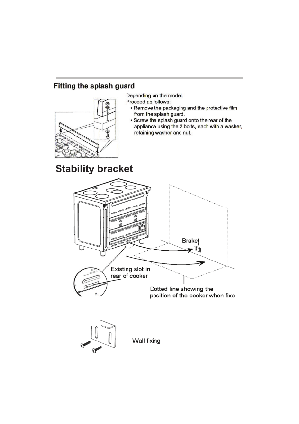
The safe operation of this appliance can only be
guaranteed if it has been professionally assembled
and installed in accordance with these instructions.
The individual who assembled and installed the
appliance is liable for damage or faults resulting from
incorrect assembly or installation.
All installation and adjustment work, as well as the
conversion to a different type of gas must be
undertaken by an authorized expert and carried out in
accordance with the currently applicable rules and
regulations of the local gas and electricity supply
company.
Shut off the supply of electricity and gas before
carrying out any work.
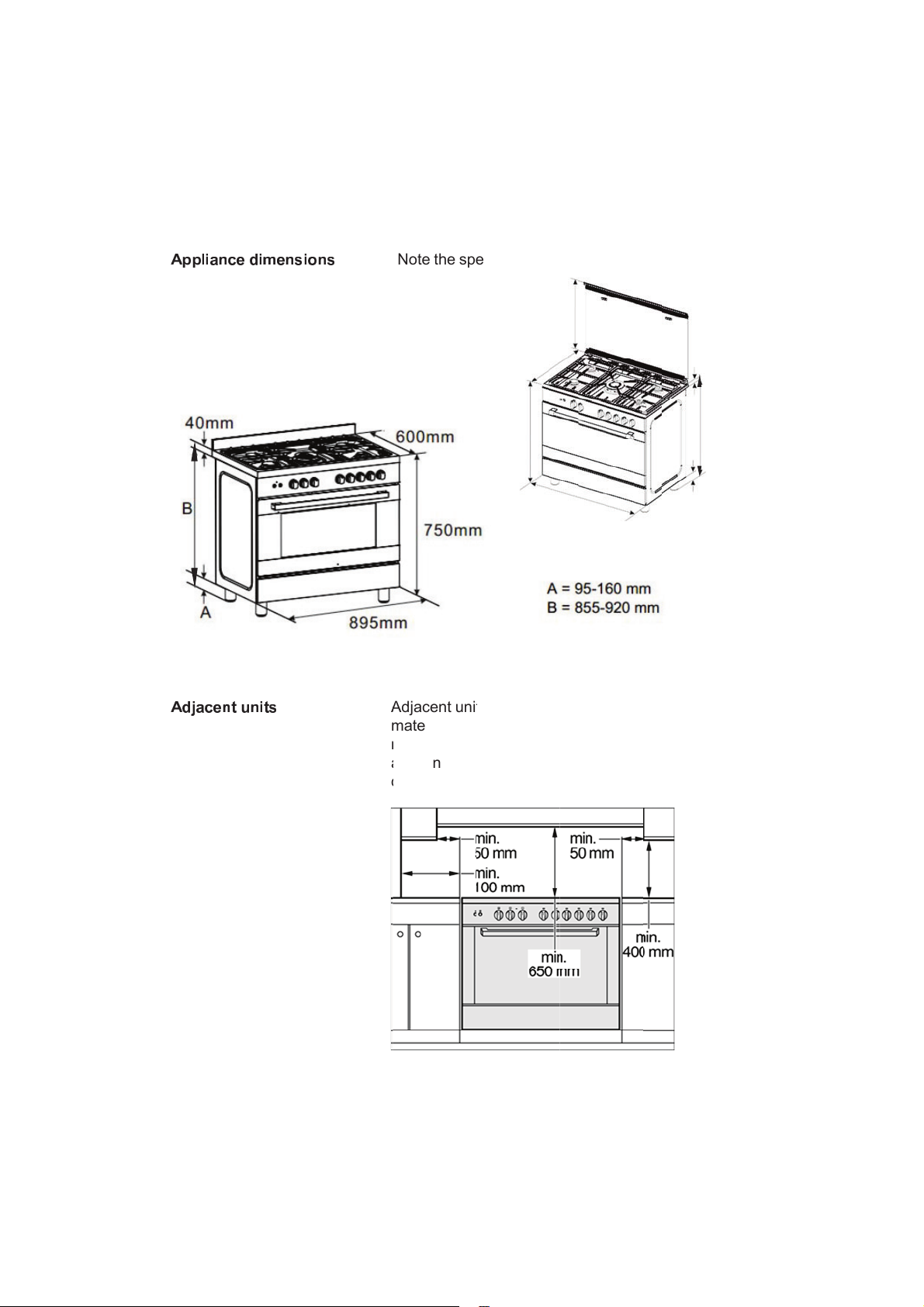
Before installing the appliance, check that the local
conditions (type of gas and pressure) are compatible
with the appliance settings. The permissible
appliance settings can be found on the rating plate.
Electrical appliances must always be earthed.
If an extractor hood is to be fitted, it must be fitted
according to the associated assembly instructions.
Ensure that the hood is fitted at least 650 mm clear of
the hob.
3

Read the following information about the appliance
and the guidelines for ventilation.
Check the condition of the appliance after unpacking
it. Do not connect the appliance if it has been
damaged in transport.
Dispose of packaging in an environmentally-friendly
manner.
.
4

! " " # $ %
&
! ' ( % ) *
&
&
) * ' $ + * & , $
-
&
. / & $ . ,
-
& ,
N
A
m
r
a
d
N
ote the sp
e
A
djacent uni
t
m
aterial. Th
e
r
esistant to t
e
a
ppliance is
d
istancessp
e
e
cified dimen
t
s must be
m
e
fronts of a
d
e
mperature
s
f
itted close t
o
e
cifiedinthe
p
sions.
m
ade of non-
c
d
jacent units
s
up to at lea
s
o
other unit
s
picturemust
c
ombustible
must be
s
t 90 °C. If t
h
, the minimu
b
emaintain
e
h
e
m
e
d.
7
600m
m
600mm
50mm
895
m
m
m
m
22mm
B
A
5

0
The technical data for the appliance can be found on
the rating plate on the back plate inside of the storage
compartment flap.
Never remove the rating plate from the appliance.
The setting values are specified on a label on the
appliance packaging.
Use the table below to record the product number
(SN no.),
factory setting for type of gas and pressure and
if applicable, the type of gas and pressure
conversions.
SN no.
After-sales service
Type of gas
Gas pressure
(factory setting)
Type of gas
Gas pressure
(conversion)
This appliance may only be set up in a sufficiently
ventilated room and according to the applicable
regulations and ventilation requirements.
Please note that the air volume required for
combustion must not be below 2 m3/h per kW of
power (see kW total power on the rating plate).
6

T
a
s
T
g
B
P
Y
o
e
I
f
a
w
c
T
his applian
c
a
djustable fe
e
s
plash guard
T
he applianc
g
uard.
B
eforehand:
•
Remove
a
especiall
y
•
Remove
t
P
roceed as f
o
•
Tilt the ap
the floor.
•
With the
p
feet into t
h
the appli
a
•
Repeat t
h
Y
ou can ma
k
o
rder to level
e
lectricity su
p
f
it is necess
a
djustable fe
e
w
hen the oth
c
ompleted.
c
e is always
s
e
t and, dep
e
.
e may also
b
a
ll parts that
y
the pan su
p
t
he accesso
r
o
llows:
pliance by r
a
p
lates in posi
h
e mounting
a
nce.
h
e process o
n
k
e the final a
d
the applian
c
p
ply have be
e
ary to pull th
e
t in fully. M
a
e
r installatio
n
s
upplied wit
h
e
nding on th
e
b
e used with
o
are not per
m
p
ports and b
u
r
ies from the
a
ising one si
d
i
tion, screw t
holes on th
e
n
the other s
d
justments t
o
c
e once the
g
en connecte
e appliance,
a
ke the final
n
tasks hav
e
h
a set of
e
model, wit
h
o
ut the spla
s
m
anently fixe
d
u
rners.
oven.
d
e slightly fr
o
he adjustabl
e
underneath
ide.
o
the feet in
g
as and
d.
screw the
settings onl
y
e
been
a
s
h
d
,
o
m
e
of
y
7

8

•
This ap
p
electric
a
•
Check t
h
applian
c
protect
e
contact
s
interrup
t
WARNI
N
•
In order
associa
t
similary
1 * " # % )
$
p
liance must
a
l supply, ch
e
h
at unit volt
a
c
e, are corre
c
e
d by a pow
e
s
separation
t
ed by the s
w
N
G: THIS A
P
to avoid ha
z
t
ed wiring s
h
qualified pe
r
$
& 2 . 3 * + % $
&
be earthed
b
e
ck that the
e
a
ge and pow
e
c
t for the su
p
e
rful switch a
of at least 3
w
itch.
P
PLIANCE
M
z
ard, any el
e
h
ould only b
e
r
sons.
&
, ) % 4 # *
T
T
L
c
P
b
y law. Befo
e
arth syste
m
e
r, marked
o
p
ply. It is ne
c
ble to disco
n
mm. Be sur
e
M
UST BE E
A
e
ctrical work
e
done by pe
T
he mains c
T
he mains c
a
• 3 x 1.5
m
• 230 V~
L
eave the m
a
c
an pull out
t
P
roceed as
f
•
Remove
t
•
Undo the
the cabl
e
•
Loosen t
h
with a ne
The cabl
e
cations.
•
Connect
t
5
erminal.
longer th
a
•
Connect
t
•
Connect
t
terminal
L
re connectin
m
in your hou
o
n the rating
c
essary that
n
nect compl
e
e
that the ea
A
RTHED
p
erformed o
r
sons autho
r
able is repla
c
a
ble must b
e
•
H0
5
•
H0
5
m
m²
a
ins cable sl
t
he applianc
e
f
ollows:
t
he rear bac
k
screw on th
e
e
in place.
h
e screw co
n
w one of the
e
must comp
l
t
he yellow-g
r
This wire m
u
a
n the
other
t
he blue neu
t
he brown p
o
L
.
n
g the applia
n
u
se is workin
g
plate applie
d
the feeding
n
e
tely the net
w
a
rth wire gre
e
n this equip
m
r
ised by the
m
ced via the r
e
of the follo
w
5
RRF
5
VVF
ightly overlo
e
for cleanin
g
k
board.
e terminal bl
n
tacts and re
e
same lengt
h
ly with the st
r
een wire to
t
u
st be at lea
s
wires.
tral wire to t
e
o
wer wire to
n
ce to the
g
correctly.
d
on the
n
etwork is
w
ork with a
e
n/yellow is
n
m
ent or its
m
anifacture
e
ar backbo
a
w
ing type:
ng so that y
o
g
purposes.
ock that fixe
s
p
lace the ca
b
h
.
i
pulated spe
c
t
he
s
t 10 mm
e
rminal N.
n
ot
o
r
rd.
o
u
s
b
le
c
ifi-
9

6% , ) -
&
% " " # $ % &
)
7 * 8 % / # .
4 / 9 & * 9
,
&
& * ) . $ - & - &
)
*
, * . . $ & 2 - 8 .
3
,
T
t
B
c
w
a
C
c
a
. 3 *
T
r
3
*
T
m
A
w
T
he applian
c
t
he currently
B
efore instal
c
onditions (t
y
w
ith the appl
a
ppliance s
e
C
onnection
t
c
arried out
p
a
pplicable st
T
he gas con
n
r
ear left of th
: ; < < = > ? @ < A
B
@ = > = C
T
he burners
m
bar) on del
A
nozzle set
f
w
ith the appl
c
e must be c
o
applicable r
e
ling the appl
y
pe of gas a
n
iance settin
g
e
ttings can b
e
t
o the gas li
n
p
rofessionall
y
a
ndards.
n
ection (ISO
e appliance.
D=C>
E
Conn
e
(and
s
LPG/NG
(and
s
are set up f
o
ivery.
f
or G20 natu
r
iance.
o
nnected in a
e
gulations.
iance, chec
k
n
d pressure)
g
s. The per
m
e
found on t
h
n
es and seal
y
according
t
228-1, 1/2")
i
E
@
B
? @ ; <
ecting piece
s
eal)
c
orrugated tu
s
eal)
o
r G30 lique
f
r
al gas (20 m
ccordance
w
k
that the loc
a
are compati
b
m
issible
h
e rating plat
fitting must
b
t
o the curren
i
s located at
t
be union
f
ied gas (29
bar) is suppl
i
w
ith
a
l
b
le
e
.
b
e
t
ly
t
he
ed
10

F G H I J K
L
) - & & * )
.
L
M N O P Q R S R Q
.
$ - &
T U
V
V
W W X Y Z [ \ ] ^ _
`
11

a- & & *
)
)
. $ & 2 . - # $ b /
*
E
*
8 $ * ' 2 % ,
I
y
r
U
o
r
O
c
a
P
E
O
.
I
f you conne
c
y
ou must al
w
r
egulator.
U
se the total
o
n the rating
r
egulator.
O
nly use co
n
c
omply with
t
a
pproved fo
r
P
roceed as
f
•
Screw th
e
(B) to th
e
•
Hold the
c
spanner
a
flexible g
•
Tighten t
h
O
nly use ap
p
.
3 9 * % ' c
c
t the applia
n
w
ays install
a
gas consum
p
plate to sel
e
n
necting line
s
t
he applicabl
r
this purpos
e
f
ollows:
e
corrugated
e
gas conne
c
c
orrugated t
u
a
nd screw t
h
a
s connecti
n
h
e clamp (D
)
p
roved seali
n
n
ce to liquefi
a
suitable ga
s
ption of the a
e
c
t
a suitabl
e
s
or flexible
h
e regulation
s
e
.
tube union (
c
tion (A).
u
be union (C
)
h
e connectin
g
n
g hose (E).
)
.
n
g compoun
d
ed gas,
s
pressure
ppliance sta
t
e
gas pressu
r
h
oses which
s
and which
a
C) and the s
e
)
in place wit
h
g
piece to a
d
to seal the
t
ed
r
e
a
re
e
al
h
a
12

d # * e $ 4 #
*
f% 8 * . g
h
a3 * ) i $
&
j & $ . $ % # /
,
*
3 - , *
h
% # h *
&
2 8 - 9 # * % i ,
,
*
I
E
f
T
c
F
t
u
A
f
S
i
L
s
I
f you use fl
e
•
the hose
s
•
the hose
s
forces.
•
the hose
s
edges or
•
the hose
s
could re
a
above ro
o
E
nsure that t
f
or inspectio
n
T
he installat
i
c
losing the g
F
it the safet
y
t
o the appro
p
u
nhindered
a
A
fter conne
c
f
or leaks usi
n
S
witch the a
p
i
nstruction
m
L
ight all the
b
s
table at bot
h
e
xible hoses,
s
do not bec
o
s
are not su
b
s
do not com
cutting edg
e
s
do not com
e
a
ch a temper
o
m tempera
t
he full length
n
.
on of a safe
t
as supply is
y
valve betw
e
p
riate room
a
a
ccess to thi
s
c
ting the gas
n
g soapy wa
t
p
pliance on
a
m
anual.
b
urners and
c
h
the high a
n
make sure
t
o
me trapped
b
ject to twisti
n
m
e into conta
c
e
s.
e
into conta
c
r
ature higher
t
ure.
h
of the hose
s
t
y valve for
o
a compulso
r
e
en the gas
c
a
nd the hob.
s
valve.
line, check t
h
t
er.
a
s describe
d
c
heck that th
e
n
d low settin
g
t
hat:
or squashe
d
n
g or pulling
c
t with sharp
t with parts t
h
than 70 °C
s
are accessi
b
o
pening and
r
y requireme
c
onnecting li
Ensure
h
e connecti
o
d
in the
e
flames rem
a
g
s.
d
.
h
at
b
le
nt.
n
e
ns
a
in
13

1 * " # % ) $ & 2 . 3 * & - k
k
D
I
t
T
c
w
T
f
m
I
n
p
k
# * ,
A
B
C
P
I
f the applia
n
t
ype of gas,
t
T
he conver
s
c
arried out
b
w
ith the appl
T
he type of
g
f
actory are i
n
m
anual.
I
n order to c
o
n
ozzles mu
s
p
rimary air
m
P
roceed as
f
•
Remove
t
•
Remove
t
from the
b
•
Remove
t
appropri
a
section “
G
•
Replace
t
supplied
n
ce is not alr
e
t
he applianc
e
ion to a diff
e
y an authori
s
icable regul
a
g
as and pre
s
n
dicated on t
h
o
nvert to a d
i
t be replace
d
m
ay have to
b
f
ollows:
t
he pan sup
p
t
he burner li
d
b
urners (C).
t
he nozzle (
D
a
te nozzle fo
G
eneral noz
z
t
he gas label
with the noz
z
e
ady set up
f
e
must be c
o
e
rent type of
s
ed expert i
n
a
tions.
s
sure that w
a
h
e insert of t
h
ifferent type
d
and the lo
w
b
e adjusted.
p
orts.
d
s (A) and b
u
D
) and repla
c
r the new ty
p
z
le table”).
with the ne
w
z
le set.
f
or the existi
n
o
nverted.
gas must b
e
n
accordanc
e
a
s preset at t
h
h
e instructio
n
of gas, the
w
flame and
u
rner spraye
c
e it with an
p
e of gas (se
w
label that
w
n
g
e
e
h
e
n
rs (B)
e
w
as
14

A
B
C
•
Place ea
c
• Position
t
top of th
e
•
Refit the
p
c
h burner sp
t
he relevant
b
e
cup.
p
an support
s
rayer (B) on
b
urner cap (
A
s
.
the burner (
C
A
) exactly o
n
C
).
n
P
P
roceed as
f
•
Open th
e
for the o
v
maximu
m
The gas
b
depress
e
release i
t
•
Close th
e
knob.
•
Through
t
loosen t
h
•
Replace
t
15 minut
e
•
Then tur
n
140.
•
Remove
t
•
Now, thr
o
panel, a
d
stable fla
Loosen t
h
or tighte
n
is correc
t
around 3
In the ca
s
tighten t
h
•
Refit the
c
•
Make su
r
the gas fl
minimu
m
•
order.
f
ollows:
e
appliance d
v
en in and tu
m
setting 250
b
urner will li
g
e
d for aroun
d
t
.
e
appliance
d
t
he gas tap
o
e internal s
e
t
he control k
n
e
s.
n
the control
k
t
he control k
o
ugh the gas
d
just the inte
r
me is burnin
h
e setting sc
r
n
it to decrea
s
t
when the h
e
to 4 mm.
s
e of a conn
e
h
e setting sc
r
c
ontrol knob
r
e that the fl
a
ow is chang
e
m
and vice ve
oor. Press t
h
rn it anti-clo
c
.
g
ht. Hold the
d
15 second
s
d
oor. Remov
e
o
pening in th
e
e
tting screw
s
nob and he
a
k
nob to the
m
nob again.
tap openin
g
r
nal setting
s
g correctly.
rew to incre
a
se the gas fl
o
e
ight of the
s
e
ction to liq
u
r
ew.
.
a
me does no
t
e
d quickly fr
o
rsa, and wh
e
h
e control kn
o
c
kwise to th
e
control kno
b
s
and then
e
the control
e
control pa
n
s
lightly.
a
t the oven f
o
m
inimum sett
i
in the contr
o
s
crew until a
a
se the gas fl
o
o
w. The setti
s
mall flame i
s
efied gas,
t
go out whe
o
m maximu
m
e
n the
o
b
b
n
el,
o
r
ng
o
l
o
w
ng
s
n
m
to
! ' ( / , . $
&
&
2 . 3 * # - l
8
8
# % + *
15

m n
B
= ; o
Liquef
ga
s
Buta
n
Prop
a
G30/
G
A p C q r p E
ied
s
n
e
ne
G
31
28-30/
37
s; t t u =
50
96
< ; v
m
27
E
60
m
n
B
= ; o r w E <
=
E
conomy burn
Wok burner
=
E
]
w ?
B
er
1,0
0
3,6
0
B
w ?
: ; < C w
q
0
0 73 g/
h
0
0 262 g
/
q
B
? @
h
h
Power of the electric heating elements
The maximum power is indicated on the rating plate
* upper heating element 1000W
* lower heating element 1700W
* upper and lower heating element 2700W
* grill element 1800W
* double grill element 2800W
* circular heating element 1200W*2=2400W
* 2 oven lamp 50W
* 2 fan oven 38W
* cooking fan 23W
16

x - , $ . $ -
&
y* h * # # $
&
&
$ & 2 . 3 * % "
"
&
2 . 3 * % " " # $
%
"
# $ % & ) *
W
e
t
w
T
T
m
I
m
f
%
& ) *
L
c
T
W
hen installi
e
nough spa
c
t
he applianc
e
w
ork.
T
he ground
u
T
he wall im
m
m
ade from n
I
f you need t
o
m
ake sure t
h
f
ully.
L
evel the ap
p
c
ompleted.
T
o do this, t
u
ng the appli
a
c
e in the fin
a
e
forwards f
o
u
nderneath
m
m
ediately be
h
on-flammab
l
o
pull the ap
p
h
at the adjus
t
p
liance onc
e
u
rn the adjus
t
a
nce, make s
a
l installation
o
r cleaning a
n
m
ust be har
d
h
ind the app
l
le material,
e
p
liance in ord
table feet ar
e
e
all other w
o
table feet.
ure that ther
e
location to
p
n
d maintena
n
d
and stable.
l
iance must
b
e
.g. tiles.
er to positio
n
e
screwed in
o
rk has been
e
is
p
ull
n
ce
b
e
n
it,
17

z z
Safety precautions
...................................................................................... 20
Property damage
....................................................................................... 22
{ | }
The control panel
....................................................................................... 24
The hob
.........................................................................................................25
The oven
. ......................................................................................................26
The minute minder
...................................................................................... 29
The storage compartment
...........................................................................332
z
Baking out the oven
. ....................................................................................33
Cleaning the burner lids and cups
. .............................................................34
Cleaning accessories
..................................................................................34
~ |
Operating gas burners
. .................................................................................35
Using the rotary spit
. .................................................................................36
Catalytic cooking compartment panels
39
Using the correct cleaning agent
. .................................................................
Removing and fitting the appliance door
. ..................................................
Replacing the oven light bulb
.....................................................................46
Aftersales service
.........................................................................................
Tips for saving energy..................................................................................... 48
Tips on using the hob ......................................................................... 48
Tips on using the oven ....................................................................... 48
Tips for using your appliance........................................................................ 49
Boiling and frying ..................................................................................
Baking ................................................................................................... 50
Roasting and grilling........................................................................... 50
18
40
42
47
49

9 % & , "
-
I R K G I
' $ , " - ,
%
a- & & *
)
-
9 . ' % + % 2 *
P I J L M S K R
P
%
#
)
. $ - & ,
R
T
a
T
d
P
i
p
a
a
C
D
i
P
I L
D
m
T
E
a
H
a
t
A
a
A
i
g
f
R
ead the in
s
T
his will ena
b
a
nd correctl
y
T
his manual
d
etails for e
a
P
lease keep
i
nstructions
a
p
lace. Pleas
e
a
ccessories
a
ppliance.
C
heck the a
p
D
o not conn
e
i
n transport.
D
ispose of p
m
anner.
T
his applian
c
E
uropean Di
a
nd Electro
n
H
ave a licen
s
a
nd gas con
n
t
ype of gas.
A
ssembly in
s
a
ppliance.
A
ny damag
e
i
ncorrectly c
o
g
uarantee.
W
f
aults cause
d
tructions for
b
le you to o
p
y
.
is valid for s
e
a
ch cooker a
r
the instructi
o
a
nd the vari
o
e
pass on th
e
to the new o
p
pliance for
d
e
ct the appli
a
a
ckaging in
a
c
e is labelle
d
rective 2002
ic Equipme
n
s
ed professi
o
n
ection and
t
s
tructions ar
e
e
caused by t
o
nnected is
n
W
e assume
n
d
by connec
t
use carefull
y
p
erate your a
e
veral mode
l
r
e possible.
o
n manual, i
n
o
us accesso
r
e
se manual
s
o
wner if you
s
d
amage afte
a
nce if it has
a
n environm
e
d
in accorda
n
2
/96/EC on
W
n
t WEEE.
o
nal carry o
u
t
he conversi
o
e
supplied
w
t
he applianc
e
n
ot covered
u
n
o liability fo
r
t
ion and setti
y
.
ppliance saf
e
l
s. Variation
s
n
stallation
r
ies in a safe
s
and
s
ell the
r unpacking
b
een damag
e
ntally-frien
d
n
ce with
W
aste Electri
c
u
t the electri
c
o
n to a differ
e
ith the
e
being
u
nder the
r
damage an
d
ng errors.
e
ly
s
in
i
t.
ed
d
ly
c
al
c
e
nt
d
19

This appliance is intended for domestic use only.
This appliance must only be used for food
preparation.
Adults and children must not operate the appliance
without supervision if:
•
they do not have the physical or mental ability;
•
or they lack the knowledge and experience
required to operate the appliance safely and
correctly.
Never let children play with the appliance.
Never drag, push or move the device once unpacked.
The appliance should be lifted and placed in the
position desired in order to prevent accidental
damage to the floor.
Open the cover plate when the oven is working.
Do not use harsh abrasive cleaners or sharp
metal scrapers to clean the oven door glass
since they can scratch the surface, which may
result in shattering of the glass.
Do not use steam cleaners to clean the
appliance.
~ 0
Never touch the burners, the surfaces of the cooking
compartment, the heating elements or the oven
steam outlets when they are hot.
Children must be kept at a safe distance from the
appliance at all times.
Open the appliance door carefully. Hot steam may
escape.
If the burners are in operation for a prolonged period,
the areas between them can become hot.
0
Never leave flammable objects on the hob or in the
storage compartment, or keep them in the cooking
compartment.
0
Never trap the mains cable of electrical appliances in
the appliance door when it is hot or pull the cable over
burners when they are hot. The cable insulation may
melt.
20
Table of contents
Other IKA Cooker manuals
Popular Cooker manuals by other brands

Sammic
Sammic SmartVide 5 user manual

Bush
Bush BEDC60W Installation & user's instructions

elvita
elvita CGS36231V quick start guide

Parkinson Cowan
Parkinson Cowan Lyris 55 GX Operating and installation instructions

Parkinson Cowan
Parkinson Cowan CALOR Sonata 50 Owners and installation instructions

AEG
AEG EH 64 DG operating instructions

DeLonghi
DeLonghi D 926 GII Installation and service instructions

Parkinson Cowan
Parkinson Cowan ALBANY Owners handbook and installation instructions

Hamilton Beach
Hamilton Beach 33999-CN use & care

Parkinson Cowan
Parkinson Cowan SIG 501 Operating and installation instructions

Bosch
Bosch HGV1F0U5 Series instruction manual

BRAYER
BRAYER BR2803 instruction manual