Ikelite DS-200 User manual

Digital
Substrobe
DDSS220000
IKELITE
B
A
T
T
O
F
F
O
N
O
N
1
/
8
1
/
4
1
/
2
F
T
T
L
Substrobe 200
Substrobe
200
I
I
K
K
E
E
L
L
I
I
T
T
E
E
D
D
S
S
2
2
0
0
0
0
S
S
u
u
b
b
s
s
t
t
r
r
o
o
b
b
e
e
I
IK
KE
EL
LI
IT
TE
ED
DS
S2
20
00
0S
SU
UB
BS
ST
TR
RO
OB
BE
E_
__
__
__
__
__
__
__
__
__
__
__
__
__
__
__
__
__
__
__
__
__
__
__
__
__
__
__
__
__
__
__
__
__
__
__
_#
#4
40
06
65
5
S
SP
PE
EC
CI
IF
FI
IC
CA
AT
TI
IO
ON
NS
S
W
We
ei
ig
gh
ht
t:
:......................................................1.8kg (3.9 lbs.) with NiMH
E
En
ne
er
rg
gy
yR
Ra
at
ti
in
ng
g:
:..........................................200 watt-sec.
C
Co
ov
ve
er
ra
ag
ge
eA
An
ng
gl
le
e:
:........................................100°
110° with diffuser
W
Wi
id
de
es
st
tL
Le
en
ns
s:
:..............................................Nikonos 15mm or SLR 20mm
18mm SLR with diffuser
G
Gu
ui
id
de
eN
Nu
um
mb
be
er
r(
(I
IS
SO
O1
10
00
0)
)f
fe
ee
et
t:
:................76 surface, 38 underwater
G
Gu
ui
id
de
eN
Nu
um
mb
be
er
r(
(I
IS
SO
O1
10
00
0)
)m
me
et
te
er
rs
s:
:..........24 surface, 12 underwater
F
Fi
ir
ri
in
ng
gM
Mo
od
de
es
s:
:............................................TTL/Auto, Manual, 1/2 M, 1/4 M, 1/8 M
Slave featuring auto exposure
using optional DS Sensor #4100.5
Slave featuring 10-manual power settings
using optional EV-Controller #4100.6
C
Co
ol
lo
or
rT
Te
em
mp
pe
er
ra
at
tu
ur
re
e:
:..................................4900°K
P
Po
ow
we
er
rS
So
ou
ur
rc
ce
e:
:............................................7.2-volt, 3.0 amp NiMH pack
F
Fl
la
as
sh
he
es
s:
:......................................................160 full power
R
Re
ec
cy
yc
cl
le
eT
Ti
im
me
e:
:............................................1.6 seconds (full power)
D
De
ep
pt
th
hR
Ra
at
ti
in
ng
g:
:............................................90m (300 feet)
2
2
IKELITE
Substrobe
200
B
A
T
T
O
F
F
O
N
O
N
1
/
8
1
/
4
1
/
2
F
T
T
L
Ready light
Switch Lock
Battery compartment door
Substrobe 200 Control Panel

3
3
I
I
K
K
E
E
L
L
I
I
T
T
E
E
D
D
S
S
2
2
0
0
0
0
S
S
u
u
b
b
s
s
t
t
r
r
o
o
b
b
e
e
Thank you for purchasing an Ikelite SUBSTROBE. Ikelite brings 40 years of
underwater photographic and lighting experience to the strobe market. Ikelite
Substrobes are designed and built in the USA by Ikelite to suit both the professional
and the amateur photographer.
D
DS
S2
20
00
0S
SU
UB
BS
ST
TR
RO
OB
BE
E_
__
__
__
__
__
__
__
__
__
__
__
__
__
__
__
__
__
__
__
__
__
__
__
__
__
__
__
__
__
__
__
__
__
__
__
__
__
__
__
__
__
__
__
__
__
__
__
__
__
_
The Ikelite DS200 strobe combines high intensity output and wide coverage angle
in a compact, versatile design. This strobe features 200 watt-sec. intensity and covers
a full 110° using the diffuser. Special soft-lite reflector provides rich reds, oranges, and
warmer flesh tones.
The Ikelite DS200 strobe is preflash compatible and operates with both traditional
film cameras and digital still cameras. Multiple firing modes are featured, including
TTL/Auto exposure. Add the optional Ikelite DS Sensor #4100.5 for wireless TTL/Auto
slave capability with select cameras or the Ikelite EV-Controller #4100.6 for 10-manual
power settings.
The DS200 electronics are safely sealed separately from the battery pack. The
industrial grade NiMH batteries recycle in an incredible 1.6 seconds and the NiMH pack
is easily interchangeable with a spare unit. The fuel gauge references the remaining
battery capacity. Aim the DS200 and illuminate your subject's colors with the built-in
modeling light / night diving light.
O
OV
VE
ER
RV
VI
IE
EW
WO
OF
FD
DS
S2
20
00
0F
FE
EA
AT
TU
UR
RE
ES
S_
__
__
__
__
__
__
__
__
__
__
__
__
__
__
__
__
__
__
__
__
__
__
__
__
__
__
__
__
__
__
__
__
__
__
__
__
_
•Separate power and firing mode switches.
• Interchangeable battery pack features industrial grade NiMH batteries.
• LED fuel gauge approximates the remaining battery capacity.
• Visual ready light indicates when strobe has recycled.
• Female Ikelite bulkhead connector accepts different camera sync cords, the Ikelite
DS Sensor #4100.5 or EV-Controller #4100.6.
• Exposure guide label references recommended exposure settings.
• Separate diffuser provides softer lighting and wider coverage angle.
• Strobe mount accommodates most Ikelite arm systems.
B
BE
EC
CO
OM
MI
IN
NG
GF
FA
AM
MI
IL
LI
IA
AR
R_
__
__
__
__
__
__
__
__
__
__
__
__
__
__
__
__
__
__
__
__
__
__
__
__
__
__
__
__
__
__
__
__
__
__
__
__
__
__
__
__
__
__
__
__
__
__
_
Before using the Ikelite Substrobe, please read this owners manual thoroughly and
retain for future reference. We recommend that you become familiar with the features
and functions of the Ikelite Substrobe before trying the camera and strobe in the water.
And if you have not done so, we suggest reading your camera owner's manual.
4
4
S
S
W
W
I
I
T
T
C
C
H
H
E
E
S
S
/
/
F
F
U
U
E
E
L
L
G
G
A
A
U
U
G
G
E
E
IKELITE
Substrobe
200
B
A
T
T
O
F
F
O
N
O
N
1
/
8
1
/
4
1
/
2
F
T
T
L
Ready light
Switch Lock
Battery compartment door
Substrobe 200 Control Panel
Waterproof cap LED Fuel Gauge
Strobe mount
Substrobe 200 Mount Side

5
5
S
S
W
W
I
I
T
T
C
C
H
H
E
E
S
S
/
/
F
F
I
I
L
L
M
M
G
G
A
A
U
U
G
G
E
E
The DS200 features separate switches for power on/off and firing modes. The line
thru the switch points to the selected position.
O
ON
N/
/O
OF
FF
FS
SW
WI
IT
TC
CH
H_
__
__
__
__
__
__
__
__
__
__
__
__
__
__
__
__
__
__
__
__
__
__
__
__
__
__
__
__
__
__
__
__
__
__
__
__
__
__
__
__
__
__
__
__
__
__
__
__
__
__
__
_
O
OF
FF
F:
:The upright switch position is OFF. The adjacent tab locks the switch in the
OFF position. To unlock, move the tab away from the switch. Always turn the Substrobe
OFF before opening the battery compartment.
O
ON
N:
:There are two ON positions. The first ON position turns on the power to the
Substrobe. The second ON position turns on both the power to the Substrobe and the
modeling light.
B
BA
AT
TT
T:
:Occasionally check the battery capacity by rotating the switch to the BATT
position and referencing the fuel gauge on the opposite side of the strobe. The BATT position
also turns ON the modeling light as a reminder that the switch is in the BATT position.
F
FU
UE
EL
LG
GA
AU
UG
GE
E_
__
__
__
__
__
__
__
__
__
__
__
__
__
__
__
__
__
__
__
__
__
__
__
__
__
__
__
__
__
__
__
__
__
__
__
__
__
__
__
__
__
__
__
__
__
__
__
__
__
__
__
__
__
__
__
_
When the switch is rotated to the BATT position, the fuel gauge on the Opposite
side of the strobe will display 0, 1, 2, or 3 red LED lights indicating the remaining charge
in the battery pack (see below). A fully charged NiMH pack will provide at least 160 full
power flashes and all 3 LED's should light. When no LED's are illuminated, then the
battery capacity is low and you may have less than 36 full power flashes remaining. For
general guidelines, refer to the following list:
• 3 LED’s - above 75%
• 2 LED’s - above 50%
• 1 LED - above 25%
• No LED - less then 25%
F
FI
IR
RI
IN
NG
GM
MO
OD
DE
ES
SW
WI
IT
TC
CH
H_
__
__
__
__
__
__
__
__
__
__
__
__
__
__
__
__
__
__
__
__
__
__
__
__
__
__
__
__
__
__
__
__
__
__
__
__
__
__
__
__
__
__
__
__
__
__
_
Multiple firing modes are featured: TTL/Auto and four manual power settings:
Full, 1/2, 1/4, and 1/8.
T
TT
TL
L/
/A
Au
ut
to
o-
Thru-The-Lens/Auto Exposure:
The camera automatically signals the
strobe to turn off when the exposure is correct. The camera must feature compatible
TTL/Auto exposure to utilize this mode on the DS200 when connected directly to the
camera. (See “Compatible Cameras” and “TTL/Auto Exposure” sections). The TTL/Auto
firing mode MUST be selected when connecting the optional DS Sensor #4100.5 or
EV-Controller #4100.6.
F
Fu
ul
ll
l-
Full Power Manual Exposure:
The strobe fires at full power each time. You
must select the correct exposure manually. Set the camera aperture based on the subject
distance (see "Exposure Guide" section).
1
1/
/2
2,
,1
1/
/4
4,
,1
1/
/8
8-
Manual Exposure Modes:
Select the appropriate power setting to
manually balance the strobe output for available light. Select 1/2, 1/4, or 1/8 power
when the strobe-to-subject distance is fixed and the manual full power setting would
over-expose with the camera aperture you have selected. The difference between e
ea
ac
ch
h
p
po
ow
we
er
rs
se
et
tt
ti
in
ng
gis one full f-stop; moving from Full power to 1/2 power decreases the light
output by one full f–stop. Changing the power setting does not alter the coverage angle.
6
6
B
B
A
A
T
T
T
T
E
E
R
R
Y
Y
C
C
O
O
M
M
P
P
A
A
R
R
T
T
M
M
E
E
N
N
T
T
Battery Compartment
Battery Compartment
Electrical contacts
Bulb holder stem, unscrew to remove.
IKELITE
B
A
T
T
O
N
O
F
F
O
N
1
/
8
1
/
4
1
/
2
F
T
T
L
o'ring
battery compartment door
Substrobe
200

7
7
B
B
A
A
T
T
T
T
E
E
R
R
Y
Y
C
C
O
O
M
M
P
P
A
A
R
R
T
T
M
M
E
E
N
N
T
T
Always turn the Substrobe OFF before opening the battery compartment located
at the back of the strobe.
Grasp the outer circular ring of the battery door, rotate counter-clockwise several
times, and then firmly pull on the battery door to remove. We suggest tilting the rear
portion of the strobe down while removing the battery door to eliminate the possibility
of water droplets falling into the battery compartment.
The center oval shaped knob on the battery door simply adjusts the exposure scale
and does not affect the o-ring seal of the battery door. The battery compartment is
sealed separately from the main strobe electronics. D
DO
ON
NO
OT
Tdisassemble the strobe. We
suggest storage of your strobe with the battery door removed to allow any hydrogen/air
mixture to escape.
B
BA
AT
TT
TE
ER
RY
YD
DO
OO
OR
RA
AN
ND
DO
O-
-R
RI
IN
NG
G_
__
__
__
__
__
__
__
__
__
__
__
__
__
__
__
__
__
__
__
__
__
__
__
__
__
__
__
__
__
__
__
__
__
__
__
__
__
__
__
__
_
The o-ring is located on the inside section of the battery door, and the door can
be separated into two sections for easy access to the o-ring. To separate the inside and
outside sections of the battery door, place the battery door in the palm of your hand
to keep the inside section from rotating. Insert a flat blade screwdriver into the center
opening of the external section, press down and rotate the screwdriver counter-
clockwise 90°, and then lift off external section of the door. Reverse the procedure to
resecure the two battery door sections.
Keep o-ring and sealing surfaces clean.
LIGHTLY LUBRICATE the o-ring with the
silicone lubricant provided. Also lightly lubricate o-ring sealing surface on the inside
of the strobe body.
Use only enough lubricant to lightly cover the o-ring; wipe off any
excess with a clean cloth. Lubricant only reduces friction; it is NOT a sealant. Never
use spray lubricant as it may crack the plastic.
R
RE
EC
CH
HA
AR
RG
GE
ET
TH
HE
EB
BA
AT
TT
TE
ER
RI
IE
ES
S_
__
__
__
__
__
__
__
__
__
__
__
__
__
__
__
__
__
__
__
__
__
__
__
__
__
__
__
__
__
__
__
__
__
__
__
__
__
__
__
__
__
_
Battery compartment accepts only Ikelite's industrial grade NiMH Pack #4063.5
See "NiMH Pack" section for recharging information.
C
CL
LO
OS
SI
IN
NG
GT
TH
HE
EC
CO
OM
MP
PA
AR
RT
TM
ME
EN
NT
T_
__
__
__
__
__
__
__
__
__
__
__
__
__
__
__
__
__
__
__
__
__
__
__
__
__
__
__
__
__
__
__
__
__
__
__
__
__
__
_
Check that the o-ring and sealing surfaces are clean and lightly lubricated.
Center the battery door over the opening and press down firmly on the door.
Continue to firmly press down on the battery door as you begin rotating the door
clockwise. Make sure that you do not cross-thread when tightening. Rotate the battery
door clockwise several times until snug.
Then rotate the door back counter-clockwise
slightly so that it will be easier to open next time.
8
8
M
M
O
O
D
D
E
E
L
L
I
I
N
N
G
G
L
L
I
I
G
G
H
H
T
T
Bulb Bulb holder
O'ring Bulb holder stem
Substrobe 200 Front
Modeling light
Modeling light reflector

9
9
M
M
O
O
D
D
E
E
L
L
I
I
N
N
G
G
L
L
I
I
G
G
H
H
T
T
The modeling light is located in the center of the strobe; it is ideal as an aiming
light and night diving light. The second ON position turns on both the power to the
Substrobe and the modeling light. Note that the BATT position also turns ON the
modeling light as a reminder that the switch is in the BATT position.
It is normal for the modeling light to flicker every few seconds as the strobe
capacitors recharge. The momentary power drain on the batteries causes the flickering
as the strobe recycles.
B
BU
UL
LB
B_
__
__
__
__
__
__
__
__
__
__
__
__
__
__
__
__
__
__
__
__
__
__
__
__
__
__
__
__
__
__
__
__
__
__
__
__
__
__
__
__
__
__
__
__
__
__
__
__
__
__
__
__
__
__
__
__
__
__
__
__
__
__
_
The bright 7.2V krypton modeling light bulb #0042.34 draws the equivalent of
under 36 full power flashes per hour.
C
CH
HA
AN
NG
GI
IN
NG
GT
TH
HE
EB
BU
UL
LB
B_
__
__
__
__
__
__
__
__
__
__
__
__
__
__
__
__
__
__
__
__
__
__
__
__
__
__
__
__
__
__
__
__
__
__
__
__
__
__
__
__
__
__
__
__
__
__
_
The modeling light bulb is accessed from inside the battery compartment. Turn the
strobe off and remove the battery door and NiMH module. Then unscrew the long stem
securing the bulb holder, and lift out the bulb holder. Tip the front of the strobe up and
the modeling light bulb will drop out of the front.
The o-ring on the bulb holder seals the battery compartment from the electronics.
Keep the o-ring clean. Use only enough lubricant to lightly cover the exposed portion
of the o-ring; wipe off any excess with a clean cloth.
To install the new modeling light bulb, tip the front of the strobe down and slide
the bulb down the groove in the battery compartment. The bulb will drop into the
reflector opening in the front. Then replace the bulb holder in the battery compartment
and tighten to secure.
A
AI
IM
MI
IN
NG
GT
TH
HE
ES
ST
TR
RO
OB
BE
E_
__
__
__
__
__
__
__
__
__
__
__
__
__
__
__
__
__
__
__
__
__
__
__
__
__
__
__
__
__
__
__
__
__
__
__
__
__
__
__
__
__
__
__
__
__
__
__
_
Use the modeling light to aim the strobe. Look thru the camera's viewfinder, and
aim the strobe so that the modeling light shines in the center of your picture area. If
your subject distance greatly changes, you should recheck the positioning of the strobe.
When using auto-focus cameras, the modeling light may be required in low light
levels to illuminate your subject to allow the camera to auto focus.
1
10
0
N
N
i
i
M
M
H
H
B
B
A
A
T
T
T
T
E
E
R
R
Y
Y
M
M
O
O
D
D
U
U
L
L
E
E
#
#
4
4
0
0
6
6
3
3
.
.
5
5
Rechargeable NiMH battery module #4063.5 is compatible only with Ikelite's DS200
strobe. It is the only battery module usable in the DS200. The NiMH module is
removable from the strobe body and additional modules are available.
A fully charged NiMH module provides at least 1
16
60
0f
fu
ul
ll
lp
po
ow
we
er
rf
fl
la
as
sh
he
es
s.
.It consists of
six C-cell industrial grade NiMH batteries (3.0Ah rating) which are considerably more
powerful than consumer NiMHs (1Ah). D
DO
ON
NO
OT
Tdisassemble the NiMH module.
C
CH
HA
AR
RG
GI
IN
NG
GT
TH
HE
EN
Ni
iM
MH
HM
MO
OD
DU
UL
LE
E_
__
__
__
__
__
__
__
__
__
__
__
__
__
__
__
__
__
__
__
__
__
__
__
__
__
__
__
__
__
__
__
__
__
__
__
__
__
_
Smart Charger #4066.1 Recharges NiMH Battery Module in 2.5 Hours.
Turn the Substrobe OFF before recharging. Recharge the NiMH module in or out of
the strobe body. Indicator light on NiMH module shows that a charge is being accepted;
it does not go out once the batteries are fully charged.
Recharge the NiMH module after each use. D
DO
ON
NO
OT
Tfully discharge NiMHs as this
shortens the battery life. Definitely recharge the NiMHs if the modeling light dims or if
the recycle time exceeds 8-10 seconds; batteries are nearly depleted. Store the NiMH
module fully charged and recharge the module for a few hours each month.
Substrobe 200 NiMH Battery Pack
NiMH Pack
Charger
Socket
IKELITE
DS200
Substrobe
CAUTION
Use only 5-6 Cell
NiMH-Charger

1
11
1
S
S
M
M
A
A
R
R
T
T
C
C
H
H
A
A
R
R
G
G
E
E
R
R
#
#
4
4
0
0
6
6
6
6
.
.
1
1
C
CA
AU
UT
TI
IO
ON
N
O
On
nl
ly
yu
us
se
e5
5-
-6
6c
ce
el
ll
lI
Ik
ke
el
li
it
te
eN
Ni
iM
MH
HC
Ch
ha
ar
rg
ge
er
r
S
SM
MA
AR
RT
TC
CH
HA
AR
RG
GE
ER
R#
#4
40
06
66
6.
.1
1_
__
__
__
__
__
__
__
__
__
__
__
__
__
__
__
__
__
__
__
__
__
__
__
__
__
__
__
__
__
__
__
__
__
__
__
__
__
__
__
__
__
__
__
_
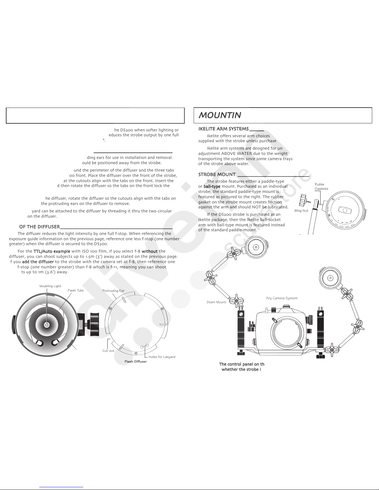
The Smart Charger #4066.1, recharges the DS200 in 2.5 hours. This variable input
voltage charger automatically adjusts for the power source voltage, ranging from 100V
to 240V. The Smart Charger adapts to current fluctuations in travel destinations with
poorly regulated power. It provides more complete recharging, prolongs battery life,
and offers trickle maintenance charge.
I
In
nt
te
er
rc
ch
ha
an
ng
ge
ea
ab
bl
le
eA
Ad
da
ap
pt
te
er
rP
Pl
lu
ug
gs
s
The Smart Charger #4066.1 offers use worldwide by accepting interchangeable
adapter plugs for different electric wall outlets. It is packaged with four interchangeable
charger plugs for USA, European, United Kingdom, and Australian electric outlets.
Choose the appropriate charger plug for your location and slide the chosen plug on the
back of the charger; it snaps into position. To interchange the charger plugs, press UP
on the charger plug to unsnap it from the back of the charger and slide another plug
into position.
S
Sm
ma
ar
rt
tC
Ch
ha
ar
rg
ge
er
rI
In
nd
di
ic
ca
at
to
or
rL
Li
ig
gh
ht
t
The charge indicator light on the Smart Charger shows the present recharge mode.
It illuminates once connected to both the electric outlet and the Ikelite battery module.
Recharge time with the Smart Charger is 2.5-hours for a full recharge of the DS200;
afterwards the Smart Charger will automatically switch to provide a trickle maintenance
charge. Only the Smart Charger is capable of providing a trickle maintenance charge
permitting the NiMH pack to be continuously charged for extended periods.
C
CO
ON
NT
TI
IN
NU
UO
OU
US
Si
il
ll
lu
um
mi
in
na
at
te
ed
dl
li
ig
gh
ht
t
Indicates that the NiMH module is being quick-charged.
S
SL
LO
OW
WB
BL
LI
IN
NK
KI
IN
NG
Gi
il
ll
lu
um
mi
in
na
at
te
ed
dl
li
ig
gh
ht
t
Indicates that the NiMH module is fully recharged and the charger is now providing
a trickle maintenance charge, which permits the NiMH module to be continuously
charged for extended time periods.
R
RA
AP
PI
ID
DB
BL
LI
IN
NK
KI
IN
NG
Gi
il
ll
lu
um
mi
in
na
at
te
ed
dl
li
ig
gh
ht
t
Indicates that the NiMH module was virtually drained (discharged) and the module
is being slow-charged to bring up the NiMHs. Once the NiMHs reach an acceptable
level, then the charger will automatically switch to the quick-charge mode.
S
S
T
T
R
R
O
O
B
B
E
E
R
R
E
E
A
A
D
D
Y
Y
L
L
I
I
G
G
H
H
T
T
R
RE
EA
AD
DY
YL
LI
IG
GH
HT
T_
__
__
__
__
__
__
__
__
__
__
__
__
__
__
__
__
__
__
__
__
__
__
__
__
__
__
__
__
__
__
__
__
__
__
__
__
__
__
__
__
__
__
__
__
__
__
__
__
__
__
__
__
__
__
_
The DS200 strobe features a visual ready light on the side of the strobe that glows
when the strobe has recycled and is ready to fire.
1
12
2
C
C
O
O
M
M
P
P
A
A
T
T
I
I
B
B
L
L
E
E
C
C
A
A
M
M
E
E
R
R
A
A
S
S
The Ikelite DS200 strobe is preflash compatible and provides optimum performance
with traditional film cameras, digital still cameras, and dSLR cameras in related Ikelite
housings. The DS200 strobe is compatible for eTTL and iTTL with the Ikelite housing system.
The appropriate sync cord or sensor must be connected to trigger the DS200 strobe.
The TTL/Auto exposure mode on the Ikelite DS200 strobe is compatible with the
following TTL/Auto exposure camera systems.
T
TR
RA
AD
DI
IT
TI
IO
ON
NA
AL
LF
FI
IL
LM
MC
CA
AM
ME
ER
RA
AS
S_
__
__
__
__
__
__
__
__
__
__
__
__
__
__
__
__
__
__
__
__
__
__
__
__
__
__
__
__
__
__
__
__
__
__
__
__
__
__
__
_
The TTL/Auto exposure mode on the Ikelite DS200 strobe is compatible with the
following TTL film camera systems. The camera reads the light passing thru-the-lens and
automatically signals the strobe to turn off when the exposure is correct.
• SLR 35mm camera in the Ikelite SLR-AF Housing or another brand SLR housing
that features Nikon-based TTL electronics.
• Nikonos V camera, Nikonos RS camera
C
C
O
O
M
M
P
P
A
A
T
T
I
I
B
B
L
L
E
E
C
C
A
A
M
M
E
E
R
R
A
A
S
S
D
DI
IG
GI
IT
TA
AL
LS
ST
TI
IL
LL
LA
AN
ND
Dd
dS
SL
LR
RC
CA
AM
ME
ER
RA
AS
S_
__
__
__
__
__
__
__
__
__
__
__
__
__
__
__
__
__
__
__
__
__
__
__
__
__
__
__
__
__
__
__
__
__
__
_
T
Tr
ri
ig
gg
ge
er
re
ed
dv
vi
ia
aS
Sy
yn
nc
cC
Co
or
rd
d
Many Ikelite Digital Still Housings and Ikelite dSLR Housings feature TTL compatible
circuitry connected with the Ikelite female bulkhead connector. Connect the Ikelite sync
cord from the Ikelite housing to the DS200 strobe for TTL auto exposure.
Some other Ikelite housing models may feature the Ikelite bulkhead connector but
offer only manual exposure because TTL conversion circuitry for that specific camera
model may be unavailable or not yet developed.
T
Tr
ri
ig
gg
ge
er
re
ed
dv
vi
ia
aS
Sl
la
av
ve
eS
Se
en
ns
so
or
r
Some digital still cameras feature a small built-in flash without a means to connect
a sync cord for an external strobe. Most of these cameras fire their built-in flash more
than once while taking a flash picture. This happens so fast it is difficult to see, but the
preflash helps the camera determine focus, exposure and color balance. After the
preflash, the camera’s built-in flash then fires to illuminate the subject and the picture
is taken. For the external strobe to provide proper exposure, it MUST be preflash
compatible to duplicate the preflash sequence. The Ikelite DS200 strobe is a preflash
compatible strobe.
For those cameras that do not offer a means to connect a sync cord, the optional
Ikelite DS Sensor #4100.5 may be compatible to trigger the DS200 strobe. Built-in slave
sensors in the DS Sensor detect the light output from the camera’s built-in flash and
automatically signal the DS200 strobe to mimic the output by starting and stopping
automatically. However, some of the newest digital still cameras feature a preflash
sequence too quick for the Ikelite DS Sensor to identify proper auto exposure, and the
Ikelite EV-Controller #4100.6 for manual exposure would then be recommended instead.
For maximum control using manual exposure, choose the optional Ikelite
EV-Controller #4100.6, which connects to the DS200 strobe and provides 10-manual
power settings in half-stop increments. The EV-Controller can be triggered using the
built-in slave sensor or by connecting an optional sync cord.

1
14
4
C
C
A
A
M
M
E
E
R
R
A
A
R
R
E
E
A
A
D
D
Y
Y
L
L
I
I
G
G
H
H
T
T
T
Tr
ri
ig
gg
ge
er
re
ed
dv
vi
ia
aS
Sy
yn
nc
cC
Co
or
rd
d
When using a TTL/Auto exposure camera (film or digital) in an Ikelite TTL-compatible
housing connected to the DS200 strobe by sync cord, the flash ready light in the camera
viewfinder and the DS200 ready light will both glow when the Substrobe has recycled and
is ready to fire.
If the Ikelite housing does not feature TTL compatible circuitry, then the ready light
in the camera viewfinder would not be triggered when the strobe has recycled.
T
Tr
ri
ig
gg
ge
er
re
ed
dv
vi
ia
aS
Sl
la
av
ve
eS
Se
en
ns
so
or
r
When using the DS200 strobe with the optional DS Sensor or EV-Controller
(without optional sync cord), the strobe is not electronically connected to the camera.
Therefore, the ready light in the viewfinder of the camera indicates when the on-camera
flash has recycled. Reference both the camera and DS200 ready lights to make sure both
flashes have fully recycled before taking the next picture.
1
13
3
T
T
T
T
L
L
/
/
A
A
U
U
T
T
O
O
E
E
X
X
P
P
O
O
S
S
U
U
R
R
E
E
Most newer cameras and strobes feature TTL/Auto exposure, which automatically
compensates for aperture, distance, extension tubes, and filters. Considering the wide
range of apertures and subject distances, select the TTL/Auto exposure mode to easily
control balanced lighting and close-up photography.
When the strobe fires, the camera reads the light and automatically signals the
strobe to turn off when the exposure is correct. Both the strobe and camera must
feature TTL/Auto exposure compatible electronics. The appropriate TTL sync cord or
optional Ikelite DS Sensor is required to relay the TTL/Auto exposure signal from the
camera to the strobe.
Please review the "Compatible Camera" section on the previous page for additional
information.
T
TT
TL
LS
SY
YN
NC
CC
CO
OR
RD
DS
S_
__
__
__
__
__
__
__
__
__
__
__
__
__
__
__
__
__
__
__
__
__
__
__
__
__
__
__
__
__
__
__
__
__
__
__
__
__
__
__
__
__
__
__
__
__
__
__
__
__
__
__
_
Ikelite offers interchangeable sync cords so that different camera systems can be
connected to the DS200 strobe. A TTL sync cord is required to send the TTL/Auto
exposure signal from the camera to the strobe.
D
DS
SS
SE
EN
NS
SO
OR
R#
#4
41
10
00
0.
.5
5_
__
__
__
__
__
__
__
__
__
__
__
__
__
__
__
__
__
__
__
__
__
__
__
__
__
__
__
__
__
__
__
__
__
__
__
__
__
__
__
__
__
__
__
__
__
__
__
__
_
The Ikelite DS Sensor provides auto exposure functions through slave sensors
enabling the Ikelite Substrobe to be moved freely and positioned virtually anywhere.
The DS Sensor connects only to Ikelite DS Substrobes and detects when the light from
the TTL strobe connected to the camera starts and stops, and automatically signals the
Ikelite Substrobe to start and stop in sync.
Many digital still cameras feature a small built-in flash without a means to connect
a sync cord for an external strobe. For these situations, the optional Ikelite DS Sensor
#4100.5 may be compatible to trigger the DS200 strobe. The sensor detects the light
output from the camera’s built-in flash and automatically signals the DS200 strobe to
mimic the output. Some of the newest digital still cameras feature a preflash sequence
too quick for the Ikelite DS Sensor to identify proper auto exposure, and the Ikelite
EV-Controller #4100.6 would then be recommended instead.
R
R
A
A
P
P
I
I
D
D
U
U
S
S
E
E
The DS200 strobe should NOT be continuously fired more than 15 times in rapid
succession. In such instances, allow the DS200 strobe to cool off for at least 10 minutes.

1
15
5
S
S
T
T
R
R
O
O
B
B
E
E
C
C
O
O
N
N
N
N
E
E
C
C
T
T
I
I
O
O
N
N
The female Ikelite bulkhead connector on the strobe permits different Ikelite sync
cords or the Ikelite DS Sensor or EV-Controller to be connected. The sync cord or sensor
relays the trigger signal to the
Substrobe.
The removable waterproof cap
seals the bulkhead connector when
neither the cord nor the sensor is
connected. The strobe bulkhead
connector must be sealed to remain
waterproof.
•
•D
DO
ON
NO
OT
Tuse TTL cord with a non-TTL Substrobe; you will damage the camera.
• D
DO
ON
NO
OT
Tleave the sync cord or sensor connected to the strobe for
prolonged
periods as electrolysis can make removal impossible.
• D
DO
ON
NO
OT
Tdisconnect the sync cord or sensor from the strobe while underwater
or when wet. Connections are NOT waterproof when not connected.
C
CO
ON
NN
NE
EC
CT
TI
IO
ON
NT
TO
OS
ST
TR
RO
OB
BE
E_
__
__
__
__
__
__
__
__
__
__
__
__
__
__
__
__
__
__
__
__
__
__
__
__
__
__
__
__
__
__
__
__
__
__
__
__
__
__
__
__
__
__
__
_
Connect either the sync cord or sensor to the Substrobe in the same manner.
T
Th
he
ec
co
on
nn
ne
ec
ct
to
or
rt
th
hr
re
ea
ad
ds
sa
ar
re
ev
ve
er
ry
yf
fi
in
ne
e;
;D
DO
ON
NO
OT
Tc
cr
ro
os
ss
st
th
hr
re
ea
ad
d.
.
I
If
fi
it
ti
is
sd
di
if
ff
fi
ic
cu
ul
lt
tt
to
ot
tu
ur
rn
n,
,y
yo
ou
ua
ar
re
ec
cr
ro
os
ss
st
th
hr
re
ea
ad
di
in
ng
g.
.
1. Turn the Substrobe OFF and make sure all components are dry. Clean and lightly
lubricate the stem o-ring and the strobe bulkhead connector threads. Check o-ring for
nicks or cuts. Never use spray lubricant.
2. Note the positioning of the receptacles and pins. Properly align the end of the
cord and insert into the strobe bulkhead connector. When using the #4103.51 cord,
which connects an Ikelite housing to an Ikelite Substrobe, both cord ends are identical;
either end can be connected to the strobe.
3. Hand-tighten the knurled retaining ring on the cord. Push the connector body
further into the bulkhead connector and continue to tighten the knurled ring.
L
LU
UB
BR
RI
IC
CA
AN
NT
T
• Use only Ikelite brand silicone lubricant with Ikelite brand o-rings as other
brand
lubricants can cause the Ikelite o-rings to swell in size.
• D
DO
ON
NO
OT
Tuse spray lubricant as it may cause cracking of the plastic.
• Ikelite silicone lubricant is provided for the cord o-ring. Use only enough
lubricant
to lightly cover the o-ring; wipe off any excess with a clean cloth.
•
Lubricant only reduces friction; it is NOT a sealant.
Stem O’ring
Retaining
Ring
Ikelite
Waterproof cap LED Fuel Gauge
Strobe mount
Substrobe 200 Mount Side
1
16
6
S
S
Y
Y
N
N
C
C
C
C
O
O
R
R
D
D
S
S
•D
DO
ON
NO
OT
Tuse TTL cord with a non-TTL Substrobe; you will damage the camera.
•D
DO
ON
NO
OT
Tleave the sync cord connected to the camera or strobe for prolonged
periods as electrolysis can make removal impossible.
•D
DO
ON
NO
OT
Tdisconnect the sync cord from the camera or strobe underwater or
when wet. Connections are NOT waterproof when not connected.
T
Th
he
ec
co
on
nn
ne
ec
ct
to
or
rt
th
hr
re
ea
ad
ds
sa
ar
re
ev
ve
er
ry
yf
fi
in
ne
e;
;D
DO
ON
NO
OT
Tc
cr
ro
os
ss
st
th
hr
re
ea
ad
d.
.
I
If
fi
it
ti
is
sd
di
if
ff
fi
ic
cu
ul
lt
tt
to
ot
tu
ur
rn
n,
,y
yo
ou
ua
ar
re
ec
cr
ro
os
ss
st
th
hr
re
ea
ad
di
in
ng
g.
.
L
LU
UB
BR
RI
IC
CA
AN
NT
T
•Use only Ikelite brand silicone lubricant with Ikelite brand o-rings as other
brand lubricants can cause the Ikelite o-rings to swell in size.
•D
DO
ON
NO
OT
Tuse spray lubricant as it may cause cracking of the plastic.Ikelite silicone
lubricant is provided for the sync cord o-ring. Use only enough lubricant to lightly
cover the o-ring; wipe off any excess with a clean cloth.
•Lubricant only reduces friction; it is NOT a sealant.
Retaining
Ring
Stem O'ring
Ikelite
Index Groove
Stem O'ring
Retaining
Ring
Nikonos

1
17
7
C
C
A
A
M
M
E
E
R
R
A
A
C
C
O
O
N
N
N
N
E
E
C
C
T
T
I
I
O
O
N
N
I
IK
KE
EL
LI
IT
TE
ET
TT
TL
LC
CO
OR
RD
DS
S_
__
__
__
__
__
__
__
__
__
__
__
__
__
__
__
__
__
__
__
__
__
__
__
__
__
__
__
__
__
__
__
__
__
__
__
__
__
__
__
__
__
__
__
__
__
__
__
__
__
_
#
#4
41
10
03
3.
.5
51
1Single strobe cord #
#4
41
10
03
3.
.5
52
2Dual strobe cord
These cords connect Ikelite Substrobes to Ikelite camera housings. Use TTL/Auto
or manual exposure modes.
C
Co
on
nn
ne
ec
ct
tI
Ik
ke
el
li
it
te
eH
Ho
ou
us
si
in
ng
g
1. Make sure all components are dry. Clean and lightly lubricate the stem o–ring
and the housing connector threads. Check the o-ring for nicks or cuts.
2. Note the positioning of the receptacles and pins. Properly align the end of the
sync cord and insert into the housing connector. When using the #4103.51 cord,
both cord ends are identical; either end can be connected to the housing.
3. Hand-tighten the knurled retaining ring on the cord. Then push the connector
body further into the housing connector and continue to tighten the knurled ring.
N
NI
IK
KO
ON
NO
OS
ST
TT
TL
LC
CO
OR
RD
DS
SF
FO
OR
RF
FI
IL
LM
MC
CA
AM
ME
ER
RA
AS
S_
__
__
__
__
__
__
__
__
__
__
__
__
__
__
__
__
__
__
__
__
__
__
__
__
__
__
__
_
#
#4
41
10
04
4.
.6
6Single strobe cord #
#4
41
10
04
4.
.6
62
2Dual strobe cord
These cords connect Ikelite Substrobes to Nikonos IV, V and RS cameras, and non-Ikelite
housings for traditional film cameras (see next section if using a non-Ikelite housing for a
digital camera). Use either TTL/Auto or manual exposure modes with the Nikonos V / RS or
suitable TTL/Auto exposure camera housing. When using the Nikonos IV or a non-TTL
housing, set the strobe in the manual mode.
C
Co
on
nn
ne
ec
ct
tN
Ni
ik
ko
on
no
os
sC
Ca
am
me
er
ra
a
1. Mount the camera tray underneath the Nikonos camera. Make sure all
components are dry. Clean and lightly lubricate the stem shaft, o-ring, and
retaining ring threads. Check the stem o-ring for nicks or cuts.
2. Align the index groove with the white dot of the camera flash socket, and insert
the stem into the camera socket.
3. Rotate the retaining ring counterclockwise until it mates with the camera socket
threads. Then carefully rotate the retaining ring clockwise and thread it into the
camera body until snug.
C
Ch
he
ec
ck
kC
Co
on
nn
ne
ec
ct
ti
io
on
nf
fo
or
rN
Ni
ik
ko
on
no
os
sV
V&
&R
RS
S
Turn ON the strobe and place camera in the TTL mode. Advance the camera to
frame #1 and the ISO dial to 800 or above. The camera's ready light will blink if the
connection is good. Afterwards, reset ISO dial for the correct film speed.
N
NI
IK
KO
ON
NO
OS
SC
CO
OR
RD
DS
SF
FO
OR
RD
DI
IG
GI
IT
TA
AL
LC
CA
AM
ME
ER
RA
AS
S_
__
__
__
__
__
__
__
__
__
__
__
__
__
__
__
__
__
__
__
__
__
__
__
__
__
__
__
__
_
#
#4
41
10
04
4.
.3
31
1Single strobe cord #
#4
41
10
04
4.
.3
32
2Dual strobe cord
Other brand housings for digital still and dSLR cameras do not offer TTL compatible
circuitry so only manual exposure is offered for the Ikelite Substrobes. Select the non-TTL
Nikonos cord #4104.31 or #4104.32 for compatibility when connecting to the Nikonos-style
female socket on the non-Ikelite housing. Follow the procedure referenced above to connect
the Nikonos cord to the housing.
1
18
8
E
E
X
X
P
P
O
O
S
S
U
U
R
R
E
E
G
G
U
U
I
I
D
D
E
E
The purpose of a strobe is to illuminate the subject and bring out the subject's true
colors. Due to the loss of color when light passes through water, move in on your subject
to photograph thru as little water as possible.
The maximum recommended lighting distance underwater with any brand strobe is
1.8m (6'). Selecting a subject at a greater distance underwater will provide mainly bluish
color silhouette type images.
E
EX
XP
PO
OS
SU
UR
RE
ES
SC
CA
AL
LE
E_
__
__
__
__
__
__
__
__
__
__
__
__
__
__
__
__
__
__
__
__
__
__
__
__
__
__
__
__
__
__
__
__
__
__
__
__
__
__
__
__
__
__
__
__
__
__
__
__
__
__
__
_
The exposure scale information is primarily intended for use with traditional film
cameras
since digital still cameras may require less light for proper exposure. The
exposure scale is compatible with TTL/Auto and Manual modes and references the
DS200 strobe output without the diffuser installed.
T
Th
he
ee
ex
xp
po
os
su
ur
re
es
sc
ca
al
le
ei
is
se
ea
as
sy
y
t
to
ou
us
se
e.
.Simply rotate the
center oval knob to align
the chosen firing mode
(F, 1/2, 1/4, 1/8) with the
film's ISO rating. Select
the "F" position when
using the TTL/Auto mode.
Then reference the
strobe-to-subject distance
next to the camera aperture
setting selected on the scale.
T
TT
TL
L/
/A
Au
ut
to
oM
Mo
od
de
ee
ex
xa
am
mp
pl
le
efor 100 ISO film speed:
Rotate center oval knob on the scale to align position "F" with ISO 100.
If you select f-8, you can shoot subjects up to 1.5m (5') away.
If you select f-4, you can shoot subjects up to 3.0m (10') away; however,
underwater we recommend subjects no farther than 1.8m (6') away.
F
Fu
ul
ll
lP
Po
ow
we
er
rM
Ma
an
nu
ua
al
lM
Mo
od
de
ee
ex
xa
am
mp
pl
le
efor 100 ISO film speed:
Rotate center oval knob on the scale to align position "F" with ISO 100.
If you select f-8, the subject should be 1.5m (5') away for proper exposure.
1
1/
/4
4P
Po
ow
we
er
rM
Ma
an
nu
ua
al
lM
Mo
od
de
ee
ex
xa
am
mp
pl
le
efor 100 ISO film speed:
Rotate center oval knob on the scale to align position "1/4" with ISO 100.
If you select f-8, the subject should be 0.75m (2.5') away for proper exposure.
C
CA
AM
ME
ER
RA
AA
AP
PE
ER
RT
TU
UR
RE
E_
__
__
__
__
__
__
__
__
__
__
__
__
__
__
__
__
__
__
__
__
__
__
__
__
__
__
__
__
__
__
__
__
__
__
__
__
__
__
__
__
__
__
__
__
__
__
__
__
_
For balanced lighting between your subject and the background, meter the
available light and set the camera aperture accordingly. A narrower aperture darkens
the background. A wider aperture may over-expose the photograph.
1
1
1
6
2
2
3
2
8
.
0
4
.
0
5
.
6
2
5
5
0
1
0
0
2
0
0
4
0
0
8
0
0
A
S
A
/
I
S
O
F
1
/
2
1
/
4
1
/
8
M
3
2
.
3
1
.
5
1
.
7
5
.
5
.
3
8
1
.
2
5
1
.
8
1
0
2
.
5
3
.
6
5
7
F
T
Substrobe 200 Exposure Guide
Center oval knob

1
19
9
D
D
I
I
F
F
F
F
U
U
S
S
E
E
R
R
#
#
0
0
5
5
8
8
1
1
.
.
3
3
The white diffuser can be secured to the front of the DS200 when softer lighting or
coverage greater than 100° is desired. The diffuser reduces the strobe output by one full
f-stop while increasing the coverage angle to 110°.
D
DI
IF
FF
FU
US
SE
ER
RI
IN
NS
ST
TA
AL
LL
LA
AT
TI
IO
ON
N_
__
__
__
__
__
__
__
__
__
__
__
__
__
__
__
__
__
__
__
__
__
__
__
__
__
__
__
__
__
__
__
__
__
__
__
__
__
__
__
__
__
__
__
_
1. The diffuser features three protruding ears for use in installation and removal.
The protruding ears on the diffuser should be positioned away from the strobe.
2. Note the three cutouts around the perimeter of the diffuser and the three tabs
inside the perimeter of the DS200 front. Place the diffuser over the front of the strobe,
and rotate the diffuser so that the cutouts align with the tabs on the front. Insert the
diffuser thru the tabs, and then rotate the diffuser so the tabs on the front lock the
diffuser in place.
3. To remove the diffuser, rotate the diffuser so the cutouts align with the tabs on
the front. Grasp the protruding ears on the diffuser to remove.
4. A lanyard can be attached to the diffuser by threading it thru the two circular
openings on the diffuser.
U
US
SE
EO
OF
FT
TH
HE
ED
DI
IF
FF
FU
US
SE
ER
R_
__
__
__
__
__
__
__
__
__
__
__
__
__
__
__
__
__
__
__
__
__
__
__
__
__
__
__
__
__
__
__
__
__
__
__
__
__
__
__
__
__
__
__
__
__
__
_
The diffuser reduces the light intensity by one full f-stop. When referencing the
exposure guide information on the previous page, reference one less f-stop (one number
greater) when the diffuser is secured to the DS200.
For the T
TT
TL
L/
/A
Au
ut
to
oe
ex
xa
am
mp
pl
le
ewith ISO 100 film, if you select f-8 w
wi
it
th
ho
ou
ut
tthe
diffuser, you can shoot subjects up to 1.5m (5’) away as stated on the previous page.
If you a
ad
dd
dt
th
he
ed
di
if
ff
fu
us
se
er
rto the strobe with the camera set at f-8, then reference one
less f-stop (one number greater) than f-8 which is f-11, meaning you can shoot
subjects up to 1m (3.6’) away.
Substrobe 200 Front
Protruding Ear
Holes for Lanyard
Cut-out
+
+
+
Flash Diffuser
Flash Tube
Tab
Modeling Light
2
20
0
M
M
O
O
U
U
N
N
T
T
I
I
N
N
G
G
T
T
H
H
E
E
S
S
T
T
R
R
O
O
B
B
E
E
I
IK
KE
EL
LI
IT
TE
EA
AR
RM
MS
SY
YS
ST
TE
EM
MS
S_
__
__
__
__
__
__
__
__
__
__
__
__
__
__
__
__
__
__
__
__
__
__
__
__
__
__
__
__
__
__
__
__
__
__
__
__
__
__
__
__
__
__
__
__
__
__
_
Ikelite offers several arm choices compatible with the DS200. The arm is NOT
supplied with the strobe unless purchased as part of a complete package.
Ikelite arm systems are designed for underwater use and may not hold the
adjustment ABOVE WATER due to the weight of some large strobes. Be careful when
transporting the system since some camera trays may not be able to support the weight
of the strobe above water.
S
ST
TR
RO
OB
BE
EM
MO
OU
UN
NT
T_
__
__
__
__
__
__
__
__
__
__
__
__
__
__
__
__
__
__
__
__
__
__
__
__
__
__
__
__
__
__
__
__
__
__
__
__
__
__
__
__
__
__
__
__
__
__
__
__
__
__
__
_
The strobe features either a paddle-type
or b
ba
al
ll
l-
-t
ty
yp
pe
emount. Purchased as an individual
strobe, the standard paddle-type mount is
featured as pictured to the right. The rubber
gasket on the strobe mount creates friction
against the arm and should NOT be lubricated.
If the DS200 strobe is purchased as an
Ikelite package, then the Ikelite ball-socket
arm with ball-type mount is featured instead
of the standard paddle-mount.
T
Th
he
ec
co
on
nt
tr
ro
ol
lp
pa
an
ne
el
lo
on
nt
th
he
eD
DS
S2
20
00
0s
st
tr
ro
ob
be
er
re
em
ma
ai
in
ns
sv
vi
is
si
ib
bl
le
er
re
eg
ga
ar
rd
dl
le
es
ss
so
of
f
w
wh
he
et
th
he
er
rt
th
he
es
st
tr
ro
ob
be
ei
is
sm
mo
ou
un
nt
te
ed
dt
to
ot
th
he
el
le
ef
ft
to
or
rr
ri
ig
gh
ht
to
of
ft
th
he
ec
ca
am
me
er
ra
a.
.
Any Camera System
#4085.26 Arm on DSLR Housng
Stem Mount
Tray Mount
Wing Nut
Rubber
Gaskets
Ikelite
Substrobe
N5 Tray
Wing Nut
Washer
Center
Cap
Ball
Clamp
Large
Wing
Nut
Universal
Tray
Wing Nut
Washer
Large
Wing
Nut
Large
Wing
Nut
Center
Cap
Center
Cap
Quick Grip
Handle
1
1
1
6
2
2
3
2
8
.
0
4
.
0
5
.
6
2
5
5
0
1
0
0
2
0
0
4
0
0
8
0
0
A
S
A
/
I
S
O
F
1
/
2
1
/
4
1
/
8
M
3
2
.
3
1
.
5
1
.
7
5
.
5
.
3
8
1
.
2
5
1
.
8
1
0
2
.
5
3
.
6
5
7
F
T
Wing Nut
Washer
Handle
Tray
N5 Tray
for Nikonos
Universal Tray for
Nikonos III, IV, V
or Motormarine II
SLR Tray

2
21
1
D
D
I
I
G
G
I
I
T
T
A
A
L
L
A
A
R
R
M
M
#
#
4
4
0
0
8
8
5
5
.
.
2
2
6
6
The articulating ball-socket Ikelite Digital Arm #4085.26 secures the DS200 strobe
to the contoured release handle on an Ikelite Digital Still Housing or SLR Housing.
The triple ball clamps on the Digital Arm
are especially versatile for macro and
wide-angle photography since the ball
clamps adjust independently for a multitude
of strobe mounting positions.
The Digital Arm #4085.26 utilizes the
larger 3
3.
.2
2c
cm
m(
(1
1.
.2
25
5"
")
)diameter balls for greater
holding power. Optional components are
available as referenced on the following pages
to modify the arm if desired.
M
MO
OU
UN
NT
TS
ST
TR
RO
OB
BE
ET
TO
OA
AR
RM
M_
__
__
__
__
__
__
__
__
__
__
__
_
A b
ba
al
ll
l-
-t
ty
yp
pe
estrobe mount is featured at
the top of the Digital Arm. The large screw
in the center of this ball mount secures to
the mount on the side of the DS200 strobe.
To secure the ball-socket arm to the
DS200, first loosen the top ball clamp
assembly and rotate the ball mount to access the large screw on the backside of the
mount. Place the strobe mount against the mount on the side of the strobe. Tighten the
large screw to secure the ball mount to the DS200.
M
MO
OU
UN
NT
TA
AR
RM
MT
TO
OH
HO
OU
US
SI
IN
NG
G_
__
__
__
__
__
__
__
__
__
__
__
__
__
__
__
__
__
__
__
__
__
__
__
__
__
__
__
__
__
__
__
__
__
__
__
__
__
__
__
__
__
_
S
St
te
em
mM
Mo
ou
un
nt
t
The stem protruding at the base of the arm snaps into the release handle on the
Ikelite housing.
Insert the stem on the arm into the release handle on the housing. Depress the
handle’s release button and slide the stem fully into the receptor. Release the button
and it should spring back to the original position locking the arm in place.
An optional longer stem #9577.33 can be purchased separately to replace the
original short stem on the Digital Arm if a convenient mounting location is needed to
secure the optional Ikelite DS Sensor or EV-Controller.
T
Tr
ra
ay
yM
Mo
ou
un
nt
t
The Ikelite tray mount is provided with the arm as a separate component to use as
an alternative means to mount the arm. The tray mount secures the ball-socket arm to
the wing nut assembly featured on select Ikelite tray systems.
To use the tray mount instead of the stem mount, loosen and remove the center
cap from the ball clamp assembly, remove the stem mount, and insert the tray mount
instead. Replace the center cap on the ball clamp assembly.
Strobe
Mounting
Bolt
Strobe
Mount
Wing Nut
Ball Clamp
Stem Mount
Release Button
Release Handle
2
22
2
I
I
K
K
E
E
L
L
I
I
T
T
E
E
B
B
A
A
L
L
L
L
-
-
S
S
O
O
C
C
K
K
E
E
T
T
C
C
O
O
M
M
P
P
O
O
N
N
E
E
N
N
T
T
S
S
B
BA
AL
LL
LC
CL
LA
AM
MP
PS
S_
__
__
__
__
__
__
__
__
__
__
__
__
__
__
__
__
__
__
__
__
__
__
__
__
__
__
__
__
__
__
__
__
__
__
__
__
__
__
__
__
__
__
__
__
__
__
__
__
__
__
__
__
__
__
_
Loosen the wing nut on the ball clamps to adjust the positioning of the arm. Each
section pivots and rotates 360° before tightening the wing nut.
The center cap limits the movement of the wing nut so that the arm cannot be
accidentally disassembled. Adjust the center cap as desired.
Interchangeable components to build
or add to the Ikelite ball-socket arm systems.
Tray mounts offered for Ikelite, Universal,
and Dovetail systems.
Ikelite arm components utilize 2.5cm (1") OR 3.2cm (1.25") diameter balls and can be
combined with ball-socket systems of TLC, Nikon, and Ultralight that use 2.5cm (1") balls
by purchasing the appropriate components.
A B C D E F G H I J K L

2
24
4
R
R
E
E
C
C
O
O
M
M
M
M
E
E
N
N
D
D
A
A
T
T
I
I
O
O
N
N
S
S
V
VI
IS
SU
UA
AL
LI
IN
NS
SP
PE
EC
CT
TI
IO
ON
NS
S_
__
__
__
__
__
__
__
__
__
__
__
__
__
__
__
__
__
__
__
__
__
__
__
__
__
__
__
__
__
__
__
__
__
__
__
__
__
__
__
__
__
__
__
__
__
__
__
_
Visual inspections are important. Take the time to visually inspect the system above
water. An improper seal or loose connection can cause a lot of damage. Always check for
leaks once you place the system in the water.
I
IN
NS
SU
UR
RA
AN
NC
CE
E_
__
__
__
__
__
__
__
__
__
__
__
__
__
__
__
__
__
__
__
__
__
__
__
__
__
__
__
__
__
__
__
__
__
__
__
__
__
__
__
__
__
__
__
__
__
__
__
__
__
__
__
__
__
__
__
__
_
We recommend adding an ALL RISK floater to your homeowner's insurance policy in
the event you damage, flood, or lose your camera or strobe. While the Ikelite Substrobe
has a limited warranty against manufacturing defects, it does not cover customer
neglect.
T
TE
EC
CH
HN
NI
IQ
QU
UE
ES
S_
__
__
__
__
__
__
__
__
__
__
__
__
__
__
__
__
__
__
__
__
__
__
__
__
__
__
__
__
__
__
__
__
__
__
__
__
__
__
__
__
__
__
__
__
__
__
__
__
__
__
__
__
__
__
_
Add a strobe to illuminate the subject and bring out the subject's true colors. Due
to the loss of color when light passes through water, move in on your subject to
photograph thru as little water as possible. The maximum recommended lighting
distance underwater with a
an
ny
yb
br
ra
an
nd
ds
st
tr
ro
ob
be
eis 1.8m (6'). Selecting a subject at a greater
distance underwater will provide mainly bluish color silhouette type images.
The white diffuser can be secured to the front of the DS200 strobe when softer
lighting or coverage greater than 100° is desired. The diffuser reduces the strobe output
by one full f-stop while increasing the coverage angle to 110°.
For balanced lighting between your subject and the background, meter the available
light and set the camera aperture accordingly. A n
na
ar
rr
ro
ow
we
er
ra
ap
pe
er
rt
tu
ur
re
edarkens the
background. A w
wi
id
de
er
ra
ap
pe
er
rt
tu
ur
re
elightens the background. If the exposures are consistently
over or under exposed, an exposure compensation control may be featured on the
TTL/Auto exposure camera that can be adjusted to compensate accordingly.
For more natural looking photos, add a second external strobe to control the
highlights and shadows of your subject. For TTL automatic exposure, both Ikelite strobes
should be connected via dual sync cord whenever possible. If maximum control for
manual exposure is preferred, choose the optional Ikelite EV-Controller #4100.6, which
provides 10-manual power settings in half-stop increments. The EV-Controller can be
triggered using the built-in slave sensor or an optional sync cord can be connected.
Always carry spare batteries. Weak batteries cause many camera and strobe
problems. Prolong the battery life by recharging the NiMH monthly even when not
used. Do not discharge the NiMH completely as this can cause permanent damage.
R
R
A
A
P
P
I
I
D
D
U
U
S
S
E
E
The DS200 strobe should NOT be continuously fired more than 15 times in rapid
succession. In such instances, allow the DS200 strobe to cool off for at least 10 minutes.
2
23
3
I
I
K
K
E
E
L
L
I
I
T
T
E
E
B
B
A
A
L
L
L
L
-
-
S
S
O
O
C
C
K
K
E
E
T
T
C
C
O
O
M
M
P
P
O
O
N
N
E
E
N
N
T
T
S
S
[A] QUICK RELEASE HANDLE WITH STROBE MOUNT
#9578.07 18cm (7"), #9578.09 23cm (9"), #9578.15 38cm (15") handle
[B] QUICK RELEASE HANDLE WITH 3.2cm (1.25") BALL
#9581.07 18cm (7"), #9581.09 23cm (9"), #9581.15 38cm (15") handle
[C] BALL WITH STEM
#9571.3: 2.5cm (1") ball with extended stem (snaps into release handle).
#9577.3: 3.2cm (1.25") ball with short stem (snaps into release handle).
#9577.33: 3.2cm (1.25") ball with extended stem (snaps in release handle).
[D] BALL 3.2cm (1.25") WITH STROBE MOUNT
#9579.04 10cm (4"), #9579.06 15cm (6"), #9579.12 30cm (12") arm
[E] BALL-TO-BALL ARM EXTENSION
#0466.42: Both balls 2.5cm (1"), arm length 10cm (4")
#0466.62: Both balls 2.5cm (1"), arm length 15cm (6")
#0466.92: Both balls 2.5cm (1"), arm length 22cm (9")
#9580.04: Both balls 3.2cm (1.25"), arm length 10cm (4")
#9580.06: Both balls 3.2cm (1.25"), arm length 15cm (6")
#9580.12: Both balls 3.2cm (1.25"), arm length 30cm (12")
Ball-to-ball adapter #0466.51: Combine different diameter ball arms.
One 2.5cm (1") ball connected to one 3.2cm (1.25") ball, length 13cm (5").
[F] BALL CLAMP
#9571.2: For arm components featuring 2.5cm (1") balls.
#9571.23: For arm components featuring 2.5cm (1") balls,
also features mounting stud extension usable for mounting the
optional Ikelite DS Sensor or EV-Controller.
#9577.2: For arm components featuring 3.2cm (1.25") balls.
[G] IKELITE TRAY MOUNT
#9577.71: 2.5cm (1") ball with tray mount for Ikelite tray/handle.
#9577.1: 3.2cm (1.25") ball with tray mount for Ikelite tray/handle.
[H] UNIVERSAL MOUNT #9577.5: 3.2cm (1.25") ball with shoe mount.
[I] DOVETAIL TRAY MOUNT #9577.7: 3.2cm (1.25") with dovetail mount.
[J] NIKONOS MOUNT #9577.6: 3.2cm (1.25") with Nikonos IV/V shoe.
[K] SUBSTROBE 50, 125 MOUNT: Use ball clamp to secure strobe mount
to ball-socket arm.
#9571.4: 2.5cm (1") ball with mount for DS50, SS50, DS200 strobe.
#9577.41: 3.2cm (1.25") ball with mount for DS50, SS50, DS200 strobe.
[L] SUBSTROBE 100A, 200 MOUNT: Use ball clamp to secure strobe mount
to ball-socket arm.
#9577.43: 2.5cm (1") ball with mount for SS100A, SS200 strobe.
#9577.42: 3.2cm (1.25") ball with mount for SS100A, SS200 strobe..

2
26
6
F
F
L
L
O
O
O
O
D
D
I
I
N
N
G
G
The DS200 battery compartment is separate from the factory sealed electronics.
Should the battery compartment flood, flush with fresh water and dry thoroughly.
Determine the cause of flooding. REPLACE THE NiMH BATTERY PACK. Never re-use
batteries that have been wet. The water could create an internal short circuit at some
later date causing a potential explosion. DO NOT disassemble the strobe or battery pack.
The potential exists for a flooded battery module to also damage some electronic
components in the main section of the strobe. Therefore, we strongly recommend that
the complete strobe be returned to Ikelite for evaluation in the event of flooding.
T
T
R
R
O
O
U
U
B
B
L
L
E
E
S
S
H
H
O
O
O
O
T
T
I
I
N
N
G
G
S
ST
TR
RO
OB
BE
EW
WI
IL
LL
LN
NO
OT
TF
FI
IR
RE
E_
__
__
__
__
__
__
__
__
__
__
__
__
__
__
__
__
__
__
__
__
__
__
__
__
__
__
__
__
__
__
__
__
__
__
__
__
__
__
__
__
__
__
__
__
__
_
1. Check the strobe ready light. Turn the strobe OFF and then back ON. Make sure
that the switch has actually clicked into position.
2. Make sure the charger is operating properly and the NiMHs are fully charged.
3. Check the mode switches on the camera and strobe.
4. Check the sync cord connection at the camera and strobe.
5. When using a sync cord between the camera and strobe, disconnect the cord
from the camera, but leave the cord connected to the strobe. Short across the
pins on the end of the cord to test fire the strobe. If you short across the wrong
receptacles on a TTL sync cord, it may damage the Substrobe electronics.
I
Ik
ke
el
li
it
te
eT
TT
TL
LC
Co
or
rd
d:
:Position the raised half-circle encompassing the receptacles
towards you. Short across the center and lower right receptacles.
N
Ni
ik
ko
on
no
os
sT
TT
TL
LC
Co
or
rd
d:
:Position the indexing groove towards you. Short across the back
and right receptacles.
If the strobe fires, the problem lies somewhere in the camera. Otherwise, return the
strobe to authorized Ikelite personnel. D
DO
ON
NO
OT
Tself-repair.
F
FL
LA
AS
SH
HC
CO
OR
RD
DC
CO
ON
NT
TA
AC
CT
TS
S
Ikelite Nikonos
2
25
5
M
M
A
A
I
I
N
N
T
T
E
E
N
N
A
A
N
N
C
C
E
E
The Ikelite SUBSTROBE should be given the same care and attention as your other
photographic equipment. In addition to normal procedures, we strongly recommend that
this strobe be returned to Ikelite periodically to be checked and pressure tested.
1. We suggest storage of your Substrobe with the battery door removed to allow
any hydrogen/air mixture to escape.
2. Always rinse the exterior of the Substrobe with fresh water after use. The strobe
can be cleaned by soaking it in a mild soapy solution. Use liquid soap; RINSE and DRY
the strobe before storage.
3. The o-ring #0104 is located on the inside section of the battery door, and the
door can be separated into two sections for easy access to the o-ring. To separate the
inside and outside sections of the battery door, place the battery door in the palm of
your hand to keep the inside section from rotating. Insert a flat blade screwdriver into
the center opening of the external section, press down and rotate the screwdriver
counter-clockwise 90°, and then lift off external section of the door. Reverse the
procedure to resecure the two door sections.
Keep the o-ring and the sealing surfaces clean. LIGHTLY LUBRICATE the o-ring
with the silicone lubricant provided. Also lightly lubricate the o-ring sealing surface on
the inside of the strobe body. Use only enough lubricant to lightly cover the o-ring; wipe
off any excess with a clean cloth. Lubricant only reduces friction; it is NOT a sealant.
Never use spray lubricant as it may cause cracking of the plastic.
4. Keep the strobe bulkhead connector threads clean and lightly lubricated. Also
keep the sync cord o-ring and threads clean and lightly lubricated.
5. Recharge the NiMH pack after each use; D
DO
ON
NO
OT
Tfully discharge the NiMHs
because you will shorten the battery life. Store the NiMH pack fully charged, and
recharge the module for a few hours each month. D
DO
ON
NO
OT
Tdisassemble the NiMH pack.
6.
The strobe is factory sealed; D
DO
ON
NO
OT
Tdisassemble.
C
CA
AU
UT
TI
IO
ON
N
L
LU
UB
BR
RI
IC
CA
AN
NT
T
•Use only Ikelite brand silicone lubricant with Ikelite brand o-rings as other
brand lubricants can cause the Ikelite o-rings to swell in size.
•D
DO
ON
NO
OT
Tuse spray lubricant as it may cause cracking of the plastic.
• Ikelite silicone lubricant is provided for the sync cord o-ring. Use only enough
lubricant to lightly cover the o-ring; wipe off any excess with a clean cloth.
• Lubricant only reduces friction; it is N
NO
OT
Ta sealant.

I
IK
KE
EL
LI
IT
TE
EU
UN
ND
DE
ER
RW
WA
AT
TE
ER
RS
SY
YS
ST
TE
EM
MS
S
50 West 33rd Street
P.O. Box 88100
Indianapolis, IN 46208 USA
317.923.4523
w
ww
ww
w.
.i
ik
ke
el
li
it
te
e.
.c
co
om
m
2
27
7
S
S
E
E
R
R
V
V
I
I
C
C
E
E
I
IK
KE
EL
LI
IT
TE
EL
LI
IM
MI
IT
TE
ED
DW
WA
AR
RR
RA
AN
NT
TY
Y_
__
__
__
__
__
__
__
__
__
__
__
__
__
__
__
__
__
__
__
__
__
__
__
__
__
__
__
__
__
__
__
__
__
__
__
__
__
__
__
_
Ikelite Substrobes are warranted against any manufacturing defects for a period of
two (2) years from the date of purchase. All other Ikelite products are warranted against
any manufacturing defects for a period of one (1) year from the date of purchase.
Defective products should be returned prepaid to Ikelite. Ikelite will, at its discretion,
repair or replace such products, and will return to customer prepaid. All other claims, of
any nature, including but not limited to bulb failure are not covered. Except as
mentioned above, no other warranty expressed or implied, applies to this Ikelite product.
We recommend adding an ALL RISK floater to your homeowner's insurance
policy in the event you damage, flood, or lose your camera or strobe.
Ikelite warranty does NOT cover customer neglect.
R
RE
ET
TU
UR
RN
NI
IN
NG
GP
PR
RO
OD
DU
UC
CT
TS
SF
FO
OR
RS
SE
ER
RV
VI
IC
CE
E_
__
__
__
__
__
__
__
__
__
__
__
__
__
__
__
__
__
__
__
__
__
__
__
__
__
__
__
__
__
__
__
__
_
Ikelite is most interested in performing any service to assure that all products
perform as intended. For repair service, return the Ikelite product to the address below
with your name, address, phone number, and a brief description of the problem.
Evidence of purchase date must be provided to obtain warranty service. Thank you.
I
IK
KE
EL
LI
IT
TE
EU
UN
ND
DE
ER
RW
WA
AT
TE
ER
RS
SY
YS
ST
TE
EM
MS
S
50 West 33 Street
P.O. Box 88100
Indianapolis, IN 46208 USA
317.923.4523
w
ww
ww
w.
.i
ik
ke
el
li
it
te
e.
.c
co
om
m
4062-03-0606