manuals.online logo
Brands
  1. Home
  2. •
  3. Brands
  4. •
  5. Ikelite
  6. •
  7. Media Converter
  8. •
  9. Ikelite 46074 User manual

Ikelite 46074 User manual

DL5 DS Link Canon TTL Converter Ikelite
Product # 46074
Video Tutorial
https://www.ikelite.com/watch-46075
Visit the link above or scan the QR code
to see how to program your DS Link TTL
Converter.
Included in the Box
• DL5 DS Link Canon TTL Converter
• Plug o-ring # 0136.13 (installed)
• Connector protector # 0301.12 (installed)
• Waterproof bulkhead cap # 9104.7 (installed)
• Silicone lubricant 1cc tube
Important Notices
»Use of this product with a nickel plated brass (silver
colored) sync cord or bulkhead may cause connectors
to permanently seize together. Separate and lubricate
connectors after each day of diving to prevent seizure.
»Use of two strobes requires a dual sync cord. Two
strobes cannot be controlled by individual converters
even if the housing is equipped with two bulkheads.
Strobe Compatibility
• Ikelite DS160, DS161
• Ikelite DS125 above serial number 5000
• Ikelite DS51
• Ikelite DS50 above serial number 70000
• Ikelite DS200 above serial number 7163
»SEA&SEA, INON, Nikonos, and other Ikelite non-DS
strobes are not capable of powering the DL5 DS Link
TTL Converter and are not compatible with this product.
Programming & Settings
Camera Program
100D Rebel SL1 6
200D Rebel SL2 6
250D Rebel SL3 1
5D II 2
5D III 2
5D IV, 5DS, 5DS R 1
6D 3
6D II 1
70D 5
750D Rebel T6i 5
77D 5
7D 6
7D II 3
800D Rebel T7i 5
80D 5
850D Rebel T8i 5
90D 7
M6 II 5
M50 I, M50 II 8
R 4
R5 4
R6, R6 II 4
R7 5
R8 5
R10 5
R100 8
RP 7
Programming the Converter
1.
Refer to the chart at http://docs.ikelite.com/reference/
ds-link-dl5-canon-chart.pdf to nd the correct program
number for your camera model.
2.
Attach a compatible Ikelite DS strobe via sync cord. If
using a dual sync cord, attach a strobe to the coiled cord
without a red band on it.
3.
Press and hold the pushbutton on the DL5 converter.
While holding the button, turn the strobe on. The LED
indicator on the DL5 will blink a blue light. The number
of blinks will indicate the program number currently set.
Factory default is program # 1 (one blink).
4.
Continue to hold the button until the indicator LED blinks
red three times. Keep holding the button as the DL5
cycles through the program settings.
5.
Each program 1-8 will be indicated by the same number
of blinks in blue. One blink for Program # 1, pause, two
blinks for Program # 2, pause, three blinks for Program #
3, pause, and so on.
6.
Release the button when the indicator blinks the number
of times corresponding to the desired program.
»The DL5 stores the program setting after the strobe is
turned off and back on. It is not necessary to reprogram
the DL5 unless a different camera model is being used.
»To check the program setting, repeat steps 2-3.
Setting Your Camera
Refer to your camera and housing instruction manuals for
recommendations on ash settings for external strobes. In
general:
• External Speedlight control must be set to Flash ring -
Enable.
• Auto Lighting Optimizer must be set to Disable.
If you are having trouble getting your strobe(s) to re or
expose properly we recommend restoring your camera
to factory default settings and making sure the hotshoe is
pushed all of the way forward.
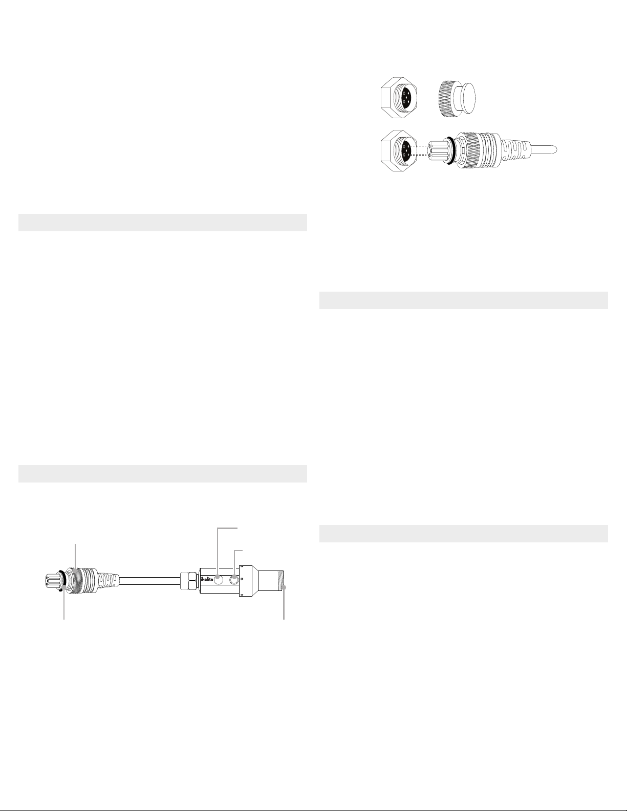
Installation and Use
Attaching the Converter
1.
Remove connector protectors and bulkhead caps from
each connection.
DL1 DS LINK
MADE
IN USA
2.
Apply a very thin, even layer of lubricant on all threads,
sealing surfaces, and the exposed portion of the plug
o-ring. Do not allow lubricant to get into the pins and
receptacles of the plug or bulkheads.
Retaining ring Mode button
LED indicator
BulkheadPlug o-ring
3.
Align plug and insert into the housing bulkhead. Each
male pin mates with a female receptacle. Failing to line up
the contacts properly before tightening may result in
damage to the converter plug and/or housing bulkhead.
4.
Hand-tighten the retaining ring.
5.
Attach a compatible sync cord to the converter using the
same method. Hold the converter while tightening the
sync cord retaining ring.
6.
Attach a compatible strobe(s) to the sync cord.
Shooting with TTL Strobe Exposure
1.
Turn strobe on. When turned on the DL5 DS Link will be
in TTL mode. The LED indicator glows blue in TTL mode.
2.
Set the strobe to TTL.
3.
Exposure compensation may be added or subtracted
through the camera’s menus. Refer to your camera
instruction manual for more information.
»It is only possible to toggle between TTL (blue LED) and
Manual (red LED) when a camera is connected.
»An incorrectly mounted hotshoe may prevent toggling
between TTL and Manual.
Shooting with Manual Strobe Exposure
1.
Push the mode button on the side of the converter. The
LED indicator light will change from blue to red.
2.
Set the strobe to full or a fractional power setting.
3.
Adjust strobe power settings as necessary for each
photo.
4.
To revert to TTL operation push the mode button and set
your strobe to TTL.
Maintenance and Storage
Post-Dive
1.
Submerge the fully assembled system in clean, fresh
water after each use. Press the mode button several
times while submerged.
2.
Remove the system from the rinse tank and ush with
running fresh water.
3.
Dry the system with a clean, lint-free cloth.
4.
Separate the components and lubricate the threads and
o-ring(s) every 2-3 days during continuous use.
Travel and Storage
1.
Separate the converter from the sync cord and housing.
2.
Wipe off the threads of each bulkhead and retaining ring
using a clean, lint-free cloth.
3.
Lightly lubricate all o-rings, threads, and sealing surfaces.
4.
Attach the connector protector and waterproof bulkhead
cap to converter ends.
Troubleshooting
https://www.ikelite.com/blogs/faq/ttl-testing-and-
troubleshooting
Limited Warranty
This Ikelite product is warranted against any manufacturing
defects for a period of one (1) year from the original date
of purchase. To obtain warranty service, the product must
be returned to Ikelite postage paid. Ikelite will, at its sole
discretion, repair or replace such products, and will return
to customer postage paid. All other claims of any nature are
not covered. Except as mentioned above, no other warranty
expressed or implied applies to this Ikelite product.

Other Ikelite Media Converter manuals

Ikelite 46075 User manual

Ikelite

Ikelite 46075 User manual

Ikelite 46076 Quick start guide

Ikelite

Ikelite 46076 Quick start guide

Ikelite 46075 Quick start guide

Ikelite

Ikelite 46075 Quick start guide

Ikelite 4401.3 Operating instructions

Ikelite

Ikelite 4401.3 Operating instructions

Popular Media Converter manuals by other brands

Teac UD-301 owner's manual

Teac

Teac UD-301 owner's manual

Rockwell Automation PowerFlex  1203-USB user manual

Rockwell Automation

Rockwell Automation PowerFlex 1203-USB user manual

Teracue ENC-100 MPEG-2 Encoder user guide

Teracue

Teracue ENC-100 MPEG-2 Encoder user guide

Baumer Hubner HOG 10 + DSL Mounting and operating instructions

Baumer

Baumer Hubner HOG 10 + DSL Mounting and operating instructions

Paradyne 5920 installation instructions

Paradyne

Paradyne 5920 installation instructions

Opticum Dekoder STB user guide

Opticum

Opticum Dekoder STB user guide

Renkforce RF-3833988 operating instructions

Renkforce

Renkforce RF-3833988 operating instructions

M-system M8YV1 instruction manual

M-system

M-system M8YV1 instruction manual

Rockwell Automation Allen-Bradley 1606-XLDD240E Reference manual

Rockwell Automation

Rockwell Automation Allen-Bradley 1606-XLDD240E Reference manual

Rohde & Schwarz RT-ZF6 manual

Rohde & Schwarz

Rohde & Schwarz RT-ZF6 manual

Coby CXCD470 instruction manual

Coby

Coby CXCD470 instruction manual

Sumake ST-2550 quick start guide

Sumake

Sumake ST-2550 quick start guide

Microchip Technology MCP16251 Reference design

Microchip Technology

Microchip Technology MCP16251 Reference design

Ethereal HDM-CAT5A Setup guide

Ethereal

Ethereal HDM-CAT5A Setup guide

4B Encoder-Flex 1024 instruction manual

4B

4B Encoder-Flex 1024 instruction manual

ZIMO MX600 Series instruction manual

ZIMO

ZIMO MX600 Series instruction manual

Parker SCMA-VADC-710 Operation manual

Parker

Parker SCMA-VADC-710 Operation manual

Crystal CS5521-AS General description

Crystal

Crystal CS5521-AS General description

manuals.online logo
manuals.online logoBrands
  • About & Mission
  • Contact us
  • Privacy Policy
  • Terms and Conditions

Copyright 2025 Manuals.Online. All Rights Reserved.