IKH WEL001 User manual
WEL001 (IBM-121)
INVERTTERI-HITSAUSKONE
INVERTER WELDING MACHINE
• Käyttöohje • Instruction manual •
Alkuperäisten käyttöohjeiden käännös • Original manual
Maahantuoja / Importer:
ISOJOEN KONEHALLI OY
Keskustie 26, 61850 Kauhajoki As, Finland
Tel. +358 - 20 1323 232, Fax +358 - 20 1323 388
www.ikh.fi
HUOMIO! Lue käyttöohjeet huolellisesti ennen laitteen käyttöä ja noudata kaikkia
annettuja ohjeita. Säilytä ohjeet myöhempää tarvetta varten.
NOTE! Read the instruction manual carefully before using the tool and follow all given
instructions. Save the instructions for further reference.
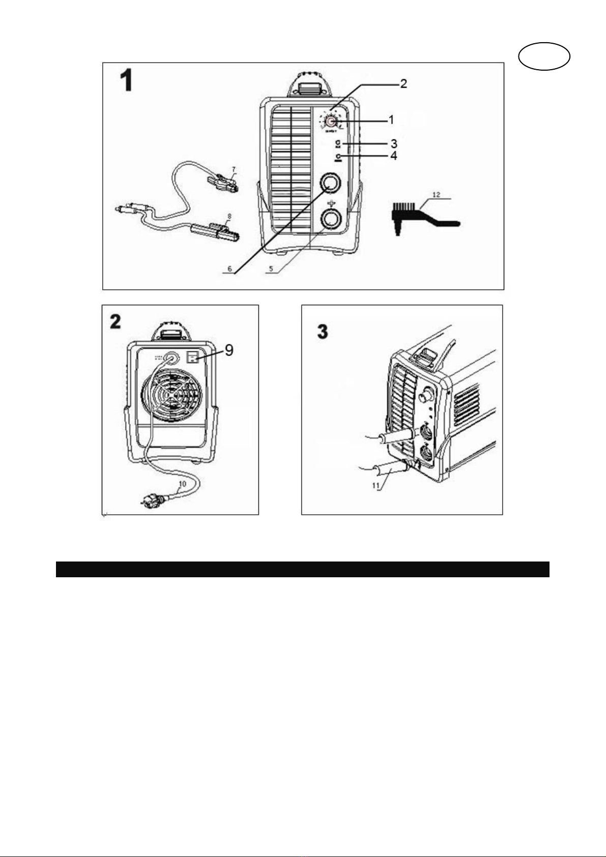
Ulkoasu (Kuva )1/2/3
1. Potentiometri hitsausjännitteen säätämiseen
2. Hitsausjännitteen asteikko
3. Käytön merkkivalo
4. Ylikuumenemisen varoitusvalo
5. Positiivinen pikaliitäntä
6. Negatiivinen pikaliitäntä
7. Kaapeli maattoliitännällä
8. Kaapeli elektrodipitimellä Virtajohto
9. Kytkin (NO/OFF)
10. Virtajohto
11. Liittimet
12. Kuonavasara harjalla
FI

SYMBOLIT JA TEKNISET TIEDOT
EN 60974-1 Euroopan standardi hitsaussarjoille rajoitetulla hitsausajalla
1-vaiheinen staattinen taajuusmuuntimen korjain
1-50Hz Syöttötaajuus
Syöttöjännite
I1max Maksimi nimellissyöttöjännite
I1ett Maksimi käyttösyöttöjännite
Nimellisjännite kuormittamattomana
Hitsauksen nimellisjännite
Hitsauspuikon halkaisija
Manuaalisen kaarihitsauksen pinnoitetuilla elektrodeilla, symboli.
1-vaiheinen virtaliitäntä
IP 21 Pölyltä ja kiinteiltä esineiltä suojattu, kosteusluokka
X Käyttöjaksonsymboli.
Tekniset tiedot

Turvallisuusohjeet
TÄRKEÄÄ
Käytä laitetta vain sen käyttötarkoitukseen ja tämän käyttöohjeen ohjeiden mukaan: Käsikaarihitsaus
pinnoitetuilla elektrodeilla. Tämän järjestelmän virheellinen käsittely voi olla vaarallista henkilöille,
eläimille ja omaisuudelle. Järjestelmän käyttäjä on vastuussa omasta ja muiden turvallisuudesta.
Lue nämä käyttöohjeet ja noudata kaikkia määräyksiä. Ainoastaan ammattitaitoisen henkilökunnan tulisi
suorittaa huolto- ja korjaustyöt.
Vain toimitettuja hitsausjohtoja saa käyttää (10 mm2kumipäällystetyt hitsausjohdot).
Varmista, että laitetta valvotaan oikein.
Varmistaaksesi, että ilma pääsee virtaamaan laitteen sisään ja ulos esteettömästi ilma-aukoista, laitetta
ei tule tukkia tai asettaa seinän viereen käytön aikana. Varmista, että laite on liitetty oikein verkkovirtaan.
Älä altista virtajohtoa vetojännitteelle. Irrota laite verkkovirrasta ennen sen siirtämistä.
Tarkasta hitsausjohtojen, elektrodipitimen ja maattoliittimen kunto; eristeen kuluminen tai paljaat johdot
voivat johtaa vaaratilanteeseen ja heikentää hitsaustulosta.
Kaarihitsaus muodostaa kipinöitä, sulaneita metallipalasia ja savua, joten suorita seuraavat: Poista
syttyvät nesteet ja/tai materiaalit työalueelta.
Varmista riittävä tuuletus.
Älä hitsaa säiliöitä, astioita tai putkia, jotka sisältävät syttyviä nesteitä tai kaasua. Vältä suoraa
kosketusta hitsauspiiriin; jäännösjännite elektrodipitimen ja maattoliittimen välillä voi olla vaarallinen. Älä
säilytä tai käytä laitetta märissä tai kosteissa olosuhteissa tai sateella.
Suojaa silmät erikoislaseilla, jotka voidaan kiinnittää hitsausnaamariin. Käytä käsineitä ja suojavaatteita,
jotka eivät ole öljyisiä tai rasvaisia ihon suojaamiseksi kaaren tuottamalta ultraviolettisäteilyltä.
Älä käytä hitsiä jään poistamiseen putkista
Muista.
Kaaren säteily voi vahingoittaa silmiä ja aiheuttaa palovammoja. Kaarihitsaus tuottaa kipinöitä ja
sulaneita metallipaloja; hitsattu metallilevy voi alkaa hehkua ja pysyy kuumana suhteellisen pitkän aikaa.
Kaarihitsaus vapauttaa höyryjä, jotka voivat olla haitallisia. Jokainen sähköisku voi olla
hengenvaarallinen.
Pysy vähintään 15 metrin etäisyydellä kaaresta jos et käytä suojavarusteita.
Suojaa itsesi (ja muut henkilöt) kaaren tuottamilta vaaratilanteilta.
Varoitus: Hitsauslaitteen sijainnin verkkovirtaliitännän olosuhteista riippuen, voi samaan
pistorasiaan liitetyt laitteet vaurioitua.
Tärkeää!
Jos syöttöpiiri ylikuormittuu, voi muut sähkölaitteet kokea häiriötä hitsauksen aikana. Jos olet epävarma,
ota yhteyttä sähköyhtiöön.
Vaaratekijät kaarihitsauksen yhteydessä
Kaarihitsaus tuottaa useita eri vaaratekijöitä. Siksi on erittäin tärkeää, että hitsaaja noudattaa seuraavia
määräyksiä, jotta hän ja muut eivät altistuisi vaaratilanteille ja laitteiden suojaamiseksi.
1. Jätä kaikki verkkovirtajärjestelmän huoltotyöt, kuten kaapelit, pistokkeet, pistorasiat jne. valtuutetun
sähkömiehen tehtäväksi. Tämä koskee etenkin johtojen vetämistä.
2. Jos tapaturma sattuu, irrota hitsauskoneen virtajohto verkkovirrasta välittömästi.
3. Jos kosketusjännitettä esiintyy, sammuta hitsauslaite välittömästi ja pyydä ammattitaitoista
huoltomiestä tarkastamaan laite.
4. Tarkasta aina, sähköliitännät ovat oikein että hitsausvirran puolella.
5. Käytä asianmukaisia käsineitä hitsauksessa. Nämä suojaavat sähköiskuilta (jäännösjännite
hitsauspiirissä), haitalliselta säteilyltä (lämpö- ja UV-säteily) ja kuumalta metallilta ja kuonaroiskeilta.

6. Käytä tukevia, eristäviä jalkineita. Kenkien tulee suojata sinua myös märissä olosuhteissa.
Avokärkiset kengät eivät sovi, koska kuumat metallipalat voivat aiheuttaa palovammoja pudotessaan.
7. Käytä työhön soveltuvaa vaatetusta. Älä käytä tekokuituvaatteita.
8. Älä katso hitsauskaareen paljain silmin, käytä hitsausnaamaria, joka täyttää DIN standardien
turvanormit. Valon ja kuumuuden lisäksi, jotka voivat aiheuttaa heijastuksia ja palovammoja, kaari
tuottaa myös UV-säteilyä. Ilman suojausta, tämä näkymätön ultravioletti säteily aiheuttaa erittäin
kivuliaan tulehduksen, joka voidaan havaita vasta usean tunnin kuluttua. Tämän lisäksi, UV-säteily
aiheuttaa auringonpaisteen aiheuttaman palovamman tyyppisiä oireita suojamaattomalle iholle.
9. Henkilökuntaa tai avustajia hitsauskaaren lähistöllä on myös varoitettava vaaroista ja heidän on
käytettävä asianmukaista suojavarustusta. Asenna tarvittaessa suojaseinät.
10. Varmista riittävä tuuletus ja ilmanvaihto hitsaukselle, etenkin pienissä tiloissa, koska hitsaus tuottaa
savua ja haitallisia kaasuja.
11. Älä hitsaa säiliöitä, joita on käytetty, kaasun, polttoaineen, mineraaliöljyn tai vastaavan aineen
säilytykseen, vaikka ne olisi tyhjennetty kauan sitten, koska mahdolliset ainejäämät voivat aiheuttaa
räjähdyksen.
12. Erikoismääräykset ovat voimassa tiloissa, joissa on tulipalo- ja/tai räjähdysvaara.
13. Hitsaukset, jotka altistuvat suurille rasituksille ja joiden on noudatettava turvallisuusmääräyksiä, saa
suorittaa vain erikoiskoulutetut ja valtuutetut hitsaajat. Esimerkki kyseisistä hitsauksista on paineastiat,
kiskot, perävaunuliitokset jne.
14. Huomautus Laitteiden sähköjärjestelmien suojajohdin voi vaurioitua hitsausvirrasta johtuen
laiminlyönnin johdosta, jos esimerkiksi maadoitusliitin asetetaan hitsauslaitteen kotelon päälle, johon
sähköjärjestelmän suojajohdin on liitetty. Hitsaus tehdään koneella, jossa on suojajohtimen liitäntä. Siksi
koneella voidaan hitsata ilman maattoliitintä. Tässä tapauksessa hitsausjännite virtaa maattoliitännästä
suojajohtimen läpi koneeseen. Korkea hitsausjännite voi aiheuttaa suojajohtimen sulamisen.
15. Varokkeen syöttöjohdoissa pistorasiaan on oltava voimassa olevien sääntöjen mukaiset (VDE 0100).
Näiden sääntöjen noudattamiseksi, vain johtojen poikkileikkaukselle sopivia varokkeita tai kytkimiä
voidaan käyttää (pistorasioiden maadoittamiseen maks. 20 A varokkeet tai 20 katkaisimet). Liian suuren
varokkeen käyttö voi johtaa johdon palamiseen ja tulipaloon.
16. Haarukkatrukilla tai nosturilla on varovaisuutta noudatettava kaasusäiliöiden ja johdonsyöttimien
kanssa.
Laite ei sovellu kaupalliseen käyttöön.
17. Lämmitys on suoritettu ympäristölämpötilassa ja käyttöjakso (kuormatekijä) 40°c asteessa on
määritetty simuloimalla.
18. Laite on Luokan I tuote Luokan H muuntajalla.
Ahtaat ja märät tilat
Kun työskentelet ahtaissa, märissä tai kuumissa tiloissa, käytä eristystukia ja välikerroksia sekä
nahasta tai johtamattomasta materiaalista valmistettuja käsineitä kehon eristämiseksi lattiasta, seinistä,
koneen johtavista osista ja vastaavista osista.
Jos käytät pieniä hitsausmuuntimia hitsaukseen tiloissa, joissa on sähköiskun vaara, esimerkiksi ahtaat
tilat johtavilla seinillä, (säiliöt, putket jne.), märissä tiloissa (jotka kastuttavat työvaatteet) ja kuumissa
tiloissa (hikoilu työvaatteisiin), ei hitsauslaitteen lähtöjännite kuormittamattomana saa ylittää 42 V
(todellinen arvo). Siksi laitetta ei saa käyttää näihin tarkoituksiin, koska lähtöjännite on tätä korkeampi.

Suojavaatteet
1. Hitsaajan on suojattava koko vartalo säteilyltä ja palavammoilta hitsauksen aikana käyttämällä
sopivia vaatteita ja kasvonaamaria
2. Sopivasta materiaalista valmistettuja käsineitä (nahka) on käytettävä molemmissa käsissä. Niiden
on oltava täysin ehjät.
3. Sopivaa esiliinaa on käytettävä vaatteiden suojaamiseen kipinöiltä ja palamiselta. Turvapukua, ja
tarvittaessa, pääsuojaa on käytettävä työtyypin vaatimusten mukaan, esim. hitsaaminen pään
yläpuolella.
4. Suojavaatteiden ja kaikkien lisävarusteiden on noudatettava “Henkilösuoja” EU-direktiiviä
5. Suoja säteilyltä ja palovammoilta
1 Ilmoita hitsauksesta aiheutuvasta silmävammojen mahdollisuudesta kyltillä tekstillä “Vaara –
älä katso liekkiin” Työpisteet tulee eristää lähistöllä olevien henkilöiden suojaamiseksi.
Luvattomien henkilöiden on pysyttävä poissa työalueelta.
2 Työpisteen lähellä olevien seinien ei tulisi olla vaaleanvärisiä tai kirkkaita. Ikkunat
päänkorkeudelle saakka on suojattava niiden läpi kulkevalta tai niistä heijastuvalta säteilyltä,
pinnoittamalla ne esimerkiksi sopivalla maalilla.
Käynnistys
Liittäminen verkkovirtaan
Ennen virtajohdon (10) kytkemistä pistorasiaan varmista, että verkkovirta on sama kuin koneen
mallikilvessä ilmoitettu.
Tärkeää! Virtapistokkeen saa vaihtaa vain valtuutettu sähköalan henkilö.
Hitsausjohdon liittäminen (Kuva 3)
Tärkeää! Varmista aina, että virtajohto on irrotettu ennen hitsausjohdon liittämistä (7/8)! Liitä hitsausjohto
kuvassa 3 osoitetulla tavalla. Liitä kaksi liitintä (11) elektrodipitimessä (7) ja maattoliitin (8) vastaaviin
pikaliittimiin (5/6) ja lukitse liittimet (11) paikalleen kääntämällä niitä myötäpäivään. Johto
elektrodipitimellä (7) liitetään tavallisesti positiiviseen napaan (5) ja maattojohto (8) negatiiviseen napaan
(6).
Käynnistys ON/OFF- virtakytkimellä (Kuva 1/2)
Käynnistä laite (9), kääntämällä potentiometriä (1) myötäpäivään nolla-asennosta hitsausvirran
asteikolla (2). Virtavalo (3) syttyy. Sammuta laite kääntämällä potentiometriä (1) vastapäivään
nolla-asentoon hitsausvirran asteikolla (2). Virtavalo (3) sammuu.
Hitsauksen valmistelu
Liitä maattoliitin (8) suoraan hitsattavaan osaan tai tukeen, jonka päällä osa on.
Varmista, että maattoliitin on suorassa yhteydessä hitsattavaan osaan. Vältä maalattuja pintoja ja/tai
eristäviä materiaaleja. Elektrodipitimen johdossa on kiinnike toisessa päässä, jota käytetään elektrodin
pitämiseen. Hitsausnaamaria on käytettävä koko hitsauksen ajan. Se suojaa silmiä säteilyltä ja
mahdollistaa kuitenkin hitsaustoiminnan näkemisen.

Hitsaus
Liitä kaikki sähköliitännät ja hitsauspiirin liitännät. Useimmat päällystetyt elektrodit liitetään positiiviseen
napaan. Osa elektrodeista on kuitenkin liitettävä negatiiviseen napaan. Noudata valmistajan ohjeita
elektrodityypin ja oikean napaisuuden varmistamiseksi. Asenna hitsausjohdot (7/8) pikaliittimiin (5/6).
Kiinnitä sitten eristämätön elektrodin pää elektrodipitimeen (7) ja liitä maattoliitin 88) hitsattavaan osaan.
Varmista, että sillä on hyvä kosketus. Kytke laite päälle ja aseta hitsausjännite, käytetyn elektrodin
mukaan potentiometrillä. Pidä hitsausnaamaria kasvojen edessä ja hankaa elektrodin päätä hitsattavaan
kohtaan samalla tavalla kuin tulitikkua sytytettäessä. Tämä on paras tapa kaaren sytyttämiseen.
Tarkasta, että käytät oikeaa elektrodia ja jännitettä testipalaan.
Elektrodi (Ø mm):
Hitsausjännite (A)
1.6 25–50A
2 40–80A
2,5 60–110A
3,2 100 – 160 A
Tärkeää!
Älä koputtele työkappaletta elektrodilla, koska se voi vaurioitua, jolloin kaaren sytyttäminen on
vaikeampaa. Kun kaari on syttynyt, yritä pitää elektrodin halkaisijan kokoinen etäisyys työkappaleeseen.
Tämä etäisyys tulee säilyttää koko hitsauksen ajan. Elektrodin kulman työsuunnassa tulee olla 20/30°.
Tärkeää!
Käytä aina pihtejä elektrodin irrottamisessa ja hitsatun työkappaleen liikuttamisessa. Huomaa, että
elektrodipidin (7) on aina asetettava alas niin, että se on eristetty kun hitsaus on valmis.
Älä irrota kuonaa ennen kuin hitsi on jäähtynyt. Jos jatkat hitsausta keskeytyksen jälkeen, on kuona
aiemmasta hitsauksesta poistettava ensin.
Ylikuumenemissuoja
Hitsauslaite on varustettu ylikuumenemissuojalla, joka suojaa hitsausmuunninta ylikuumenemiselta. Jos
ylikuumenemissuoja laukeaa, syttyy merkkivalo (4) laitteessa. Anna laitteen jäähtyä jonkin aikaa.
Kunnossapito
Poista pöly ja lika säännöllisesti laitteesta. Käytä puhdistuksessa pehmeää harjaa tai pyyhettä. Älä
puhdista konetta petrolilla tai alkoholilla.

Layout (Fig. 1/2/3)
1. Potentiometer for adjusting the welding current
2. Welding current scale
3. Indicator lamp for operation
4. Warning lamp for overheating
5. Positive quick-lock coupling
6. Negative quick-lock coupling
7. Cable with ground terminal
8. Cable with electrode holder Power cable
9. Switch (NO/OFF)
10. Power cable
11. Connectors
12. Slag hammer with brush
GB

SYMBOLS AND TECHNICIAL DATA
EN 60974-1 European standard for welding sets for manual are welding with limited on time
Single-phase static frequency converter transformer rectifier
1-50 Hz Supply frequency
Supply voltage
I1max Rated maximum supply current
I1ett Maximum effective supply current
Rated no load voltage
Rated welding current
Welding rod diameter
Symbol for manual arc welding with covered electrodes.
Single-phase mains connection
IP 21 Resistance to dust, solid objects and moisture class
X Duty cycle symbol.
Technical data

Safety information
IMPORTANT
Only use this appliance for the purpose for which it is designed and as described in these instructions:
Manual arc welding with coated electrodes. Handling this system incorrectly may be hazardous for
persons, animals and property. The user of this system is responsible for his/ her own safety and for the
safety of others.
Read these operating instructions and follow all the regulations. Repairs and/or maintenance work may
only be carried out by qualified personnel.
Use only the welding cables supplied (10 mm2rubber-sheathed welding cables).
Ensure that the appliance is looked after properly.
To ensure that sufficient air can be drawn in through the ventilation slits, the appliance should not be
constricted or placed next to a wall while it is operating. Make sure that the appliance is correctly
connected to the mains supply.
Do not subject the mains lead to any tensile stress. Unplug the appliance before you change its position.
Check the condition of the welding cables, the electrode tongs and the earth terminals; wear on the
insulation and the live parts may result in dangerous conditions and reduce the quality of the welding
work.
Arc welding generates sparks, molten metal particles and smoke, so the following is required: Remove
all inflammable substances and/or materials from the working area.
Ensure that there is adequate ventilation.
Do not weld on tanks, vessels or pipes that have contained inflammable liquids or gases.Avoid all direct
contact with the welding circuit; the idling voltage between the electrode tongs and the earth terminal
may be dangerous. Do not store or use the appliance in wet or damp conditions or in the rain.
Protect your eyes with specially designed goggles, which you can attach to the supplied safety shield.
Wear gloves and dry safety clothing that are not contaminated by any oil or grease to ensure that your
skin is not exposed to ultraviolet radiation from the arc.
Do not use this welder to defrost pipes
Remember.
The radiation from the arc can damage your eyes and cause burns on skin. Arc welding generates
sparks and droplets of molten metal; the welded workpiece may start to glow and will remain very hot for
a relatively long period of time. Arc welding releases vapors that may be harmful. Every electric shock is
potentially fatal.
Do not approach the arc within a radius of 15 m unprotected.
Protect yourself (and others around you) against the possible hazardous effects of the arc.
Warning: Depending on the mains connection conditions at the connection point of the welding set, other
consumers connected to the mains may suffer faults.
Important!
If the supply mains and circuits are overloaded, other consumers may suffer interference during the
welding work. If you have any doubts, contact your electricity supply company.
Sources of danger during arc welding
Arc welding results in a number of sources of danger. It is therefore particularly important for the welder
to comply with the following rules so as not to place himself or others in danger and to avoid endangering
people and equipment.
1. Have all work on the mains voltage system, for example on cables, plugs, sockets, etc., performed
only by trained electricians. This particularly applies to configuring intermediate cables.
2. If an accident occurs, disconnect the welding power source from the mains immediately.

3. If electric touch voltages occur, switch off the welding set immediately and have it checked by an
expert.
4. Always check for good electrical contacts on the welding current side.
5. Wear insulating gloves on both hands for welding. These offer protection from electric shocks (idling
voltage in the welding circuit), harmful radiation (Heat and UV radiation) and from glowing metal and slag
spatter.
6. Wear firm, insulated footwear. Your shoes should also protect you in wet conditions. Open- toed
footwear is not suitable since falling droplets of glowing metal will cause burns.
7. Wear suitable clothing, do not wear synthetic clothes.
8. Do not look into the arc with unprotected eyes, use only a welding safety shield with the proper safety
glass in compliance with DIN standards. In addition to light and heat, which may cause dazzling and
burns, the arc also gives off UV radiation. Without proper protection, this invisible ultraviolet radiation
causes very painful conjunctivitis, which will only be noticeable several hours later. In addition, UV
radiation will cause sunburn-type symptoms on unprotected parts of the body.
9. Personnel or assistants in the vicinity of the arc must also be notified of the dangers and provided with
the required protection; if necessary install safety walls.
10. Ensure adequate ventilation for welding, particularly in small rooms since the process causes smoke
and harmful gases.
11. Do not carry out any welding work on tanks that have been used to store gases, fuels, mineral oil or
the like, even if they have been empty for a lengthy period of time, since any residue will result in a
danger of explosion.
12. Special regulations apply in areas where there is a potential risk of fire and/or explosion.
13. Welds that are exposed to large stresses and must comply with safety requirements may only be
completed by specially trained and approved welders. Examples of such welds include pressure vessels,
rails, trailer hitches, etc.
14. Note: It must be noted that the protective conductor in electrical systems of appliances may be
destroyed by the welding current in the event of negligence, for example if the earth terminal is placed on
the welding set casing to which the protective conductor of the electrical system is connected. The
welding work is completed on a machine with a protective conductor connection. It is therefore possible
to weld on the machine without having connected the earth terminal to it. In this case the welding current
will flow from the earth terminal through the protective conductor to the machine. The high welding
current may cause the protective conductor to melt.
15. The fuses on the supply cables to the mains sockets must comply with the relevant regulations (VDE
0100). To comply with these regulations, only fuses or circuit breakers suitable for the cross-section of
the cables may be used (for earthling contact sockets max. 20 Afuses or 20 Acircuit breakers). The use
of too high a fuse may result in the cable burning and fire damage to the building.
16. By fork-lift or crane, and precautions to be taken with gas cylinders, wire feeders.
This appliance is not designed for commercial use.
17. The heating have been carried out at ambient temperature and the duty cycle (duty factor) at 40°c
has been determined by simulation.
18. It’s class I product with class H transformer.
Constricted and wet areas
When working in constricted, wet or hot areas, use insulating supports and intermediate layers as well
as slip-on gloves made of leather or other non- conductive materials to insulate your body against the
floor, walls, conductive parts of the machine and the like.
If you use small welding transformers for welding in places with an increase electrical risk, for example in
constricted areas with conductive walls, (tanks, pipes, etc.), in wet areas (which make work clothes wet)
and in hot areas (perspiration on work clothes), the output voltage of the welding set when idling must

not exceed 42 V (effective value). Therefore, the appliance may not be used for these purposes because
its output voltage is higher than this.
Safetyclothing
1. While working, the welder must protect his entire body from radiation and burns by wearing
suitable clothing and a face guard
2. Slip-on gloves made of a suitable material (leather) must be worn on both hands. They must be in
perfect condition.
3. Suitable aprons must be worn to protect clothing from sparks and burns. A safety suit and, if
necessary, head protection must be worn it required by the type of work in question, e.g. overhead
welding
4. The protective clothing used as well as all Accessories must be in compliance with the “Personal
safety equipment” EU Directive
5. Protection from radiation and burns
1 Provide information about the risk to eyes at the working site in the form of a poster with the
wording “Caution – do not look at the flames” Workplaces are to be screened off wherever
possible so that personnel in the vicinity are protected. Unauthorized persons are to be kept
away from welding work.
2 The wall in the immediate vicinity of stationary workplaces should not have a light color or
sheen. Windows up to head height are to be protected against radiation passing through them
or reflecting off them, for example by coating them with a suitable paint.
Starting up
Connecting to the mains power supply
Before you connect the power cable (10) to the mains power supply, make sure that the data on the
rating plate is the same as that for your mains supply.
Important! The mains plug may only be replaced by a qualified electrician.
Connecting the welding cable (Fig. 3)
Important! Always make sure the device is unplugged before carrying out any connection work on the
welding cable (7/8)! Connect the welding cable as shown in Fig. 3. To do so, connect the two connectors
(11) on the electrode holder (7) and the ground terminal (8) to the corresponding quick-lock couplings
(5/6) and lock the connectors (11) in place by turning them in a clockwise direction. The cable with the
electrode holder (7) is normally connected to the positive pole (5) and the cable with the ground terminal
(8) to the negative pole (6).
Switching ON/OFF (Fig. 1/2)
To switch on the device (9), turn the potentiometer (1) in a clockwise direction from the zero position on
the welding current scale (2). The indicator lamp for operation (3) then comes on. To switch off the
device, turn the potentiometer (1) in a counter- clockwise direction back to the zero position on the
welding current scale (2). The indicator lamp for operation (3) then goes out.
Welding preparations
Connect the earth terminal (8) direct to the part to be welded or to the support on which the part is
resting.
Ensure that the earth terminal is in direct contact with the part to be welded. You should therefore avoid
coated surfaces and/or insulated materials. The electrode holder cable has a special clamp at one end,
which is used to secure the electrode. The welding safety shield must be used at all times for welding. It
protects your eyes from the radiation emitted by the arc and nevertheless enables you to watch the
welding process.

Welding
Connect all the electrical connections for the power supply and for the welding current circuit. Most
coated electrodes are connected to the positive pole. However, some types of electrode have to be
connected to the negative pole. Ensure that you observe the information supplied by the manufacturer in
relation to the type of electrode and correct polarity. Fit the welding cables (7/8) to the quick-lock
couplings (5/6) accordingly. Then fasten the unsheathed end of the electrode in the electrode holder (7)
and connect the ground terminal (8) to the part you wish to weld. Ensure that a good electric contact is
made. Switch on the device and set the welding current, depending on the electrode used, using the
potentiometer. Hold the safety shield in front of your face and rub the tip of the electrode on the part you
wish to weld as if you were striking a match. This is the best method of igniting an arc.
Check that you have the correct electrode and current strength on a test part.
Electrode (Ø mm):
Weldingcurrent(A)
1.6 25–50A
2 40–80A
2.5 60–110A
3.2 100 – 160 A
Important!
Do not dab the workpiece with the electrode since it could be damaged, making it more difficult to ignite
the arc as soon as the arc has ignited, attempt to keep it a distance from the workpiece equivalent to the
diameter of the electrode.
This distance should be kept as constant as possible during the welding process. The angle of the
electrode in the direction in which you are working should be 20/30°.
Important!
Always use tongs to remove spent electrodes and to move parts that you have just welded. Please note
that the electrode holder (7) must always be put down so that it is insulated after you have completed the
welding work.
Do not remove the slag until the weld has cooled. If you want to continue a weld after an interruption, the
slag from your initial attempt must first be removed.
Overheating guard
The welding set is fitted with an overheating guard that protects the welding transformer from
overheating. If the overheating guards trips, the control lamp (4) on your set will be lit. Allow the welding
set to cool for a time.
Maintenance
Remove dust and dirt from the machine at regular intervals. Cleaning is best carried out with a fine
brush or a cloth. Do not clean the machine by petroleum sprit.

EY-VAATIMUSTENMUKAISUUSVAKUUTUS
Isojoen Konehalli Oy
Keskustie 26, 61850 Kauhajoki As
Suomi
vakuuttaa täten, että
KAARIHITSAUSKONE
malli no. WEL001 (IBM-121), WEL002 (S-160),
WEL003 (S-200), WEL004 (MG-175), WEL005 (MG-195)
täyttää pienjännitedirektiivin 2006/95/EY
sekä standardin EN 60974-1:2005 vaatimukset.
Mikäli tuotteen teknisiä ominaisuuksia tai
käyttöominaisuuksia muutetaan ilman valmistajan
suostumusta tämä vakuutus lakkaa olemasta voimassa.
Päiväys: 27.07.2011
Allekirjoitus:
____________________
Harri Altis - Ostopäällikkö
(valtuutettu kokoamaan teknisen tiedoston)
EG-FÖRSÄKRAN OM ÖVERENSSTÄMMELSE
Isojoen Konehalli Oy
Keskustie 26, 61850 Kauhajoki As
Finland
intygar härmed att
BÅGSVETSMASKIN
modell nr. WEL001 (IBM-121), WEL002 (S-160),
WEL003 (S-200), WEL004 (MG-175), WEL005 (MG-195)
följer bestämmelserna i lågspänningsdirektivet 2006/95/EG
samt standarden EN 60974-1:2005.
Om produktens tekniska eller andra egenskaper förändras utan
tillverkarens medgivande, gäller denna överensstämmelse inte
längre.
Datum: 27.07.2011
Underteckning:
____________________
Harri Altis - Inköpschef
(behörig att ställa samman den tekniska dokumentationen)
EC-DECLARATION OF CONFORMITY
Isojoen Konehalli Oy
Keskustie 26, 61850 Kauhajoki As
Finland
herewith declares that
ARC WELDING MACHINE
model no. WEL001 (IBM-121), WEL002 (S-160),
WEL003 (S-200), WEL004 (MG-175), WEL005 (MG-195)
fulfils the requirements of the Low Voltage Directive
2006/95/EC
as well as the standard EN 60974-1:2005.
This declaration is not anymore valid if the technical features
or other features of the tool are changed without
manufacturer’s permission.
Date: 27.07.2011
Signature:
____________________
Harri Altis - Purchase Manager
(authorized to compile the Technical File)
Table of contents
Languages:
Other IKH Welding System manuals


Popular Welding System manuals by other brands

Lincoln Electric
Lincoln Electric SYNERGIC 7 AND 7H IM557 Operator's manual

Cebora
Cebora PLASMA PROF 123 ACC Service manual

Miller
Miller Multimatic 220 AC/DC quick reference

Miller
Miller Legend 302 owner's manual

TOOL WAREHOUSE
TOOL WAREHOUSE SG-8900 manual

Panasonic
Panasonic YD-350GY4 operating instructions


