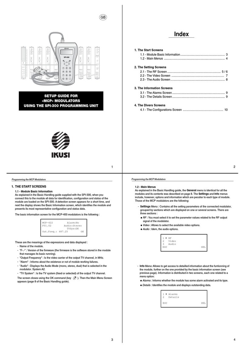
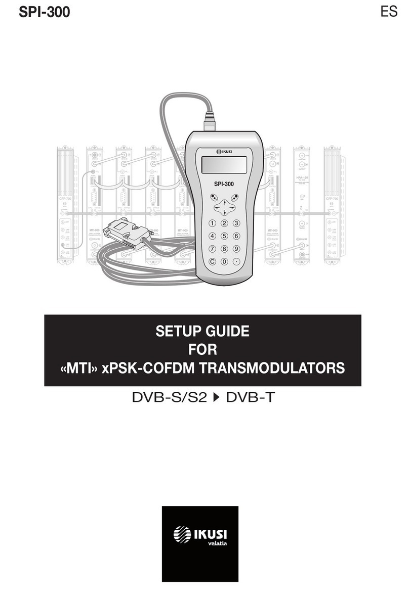
IKUSI SPI-300 User manual

2
34
SETUP GUIDE FOR
THE «MCP-800» TWIN MODULATORS
USING THE SPI-300 PROGRAMMING UNIT
+12V
HPA-120
BROADBAND AMPLIFIER
INPUT
OUTPUT
GAIN
Ref. 4426
47-862 MHz
EXT INPUT
OUTPUT TEST
- 0 dB
Gain 6 dB
-20 dB
ON
INPUT TEST
CFP-700
POWER
+24V
+18V
300 mA
(22 KHz)
+12V
5A
+13V
300 mA
(22 KHz)
+18V
300 mA
+13V
300 mA
:700 mA
I
TOT (MAX)
CONTROL
STATUS
+12V
RF OUT
Ref. 3849
MCP-801
TWIN TV MODULATOR
VIDEO VIDEO
AUDIO
L AUDIO
L
AUDIO
R AUDIO
R
V/A 1 V/A 2
M
O
N
O
M
O
N
O
CONTROL
STATUS
+12V
RF OUT
Ref. 3849
MCP-801
TWIN TV MODULATOR
VIDEO VIDEO
AUDIO
L AUDIO
L
AUDIO
R AUDIO
R
V/A 1 V/A 2
M
O
N
O
M
O
N
O
CONTROL
STATUS
+12V
RF OUT
Ref. 3849
MCP-801
TWIN TV MODULATOR
VIDEO VIDEO
AUDIO
L AUDIO
L
AUDIO
R AUDIO
R
V/A 1 V/A 2
M
O
N
O
M
O
N
O
CONTROL
STATUS
+12V
RF OUT
Ref. 3849
MCP-801
TWIN TV MODULATOR
VIDEO VIDEO
AUDIO
L AUDIO
L
AUDIO
R AUDIO
R
V/A 1 V/A 2
M
O
N
O
M
O
N
O
CONTROL
STATUS
+12V
RF OUT
Ref. 3849
MCP-801
TWIN TV MODULATOR
VIDEO VIDEO
AUDIO
L AUDIO
L
AUDIO
R AUDIO
R
V/A 1 V/A 2
M
O
N
O
M
O
N
O
CONTROL
STATUS
+12V
RF OUT
Ref. 3849
MCP-801
TWIN TV MODULATOR
VIDEO VIDEO
AUDIO
L AUDIO
L
AUDIO
R AUDIO
R
V/A 1 V/A 2
M
O
N
O
M
O
N
O
CONTROL
STATUS
+12V
RF OUT
Ref. 3849
MCP-801
TWIN TV MODULATOR
VIDEO VIDEO
AUDIO
L AUDIO
L
AUDIO
R AUDIO
R
V/A 1 V/A 2
M
O
N
O
M
O
N
O
CONTROL
STATUS
+12V
RF OUT
Ref. 3849
MCP-801
TWIN TV MODULATOR
VIDEO VIDEO
AUDIO
L AUDIO
L
AUDIO
R AUDIO
R
V/A 1 V/A 2
M
O
N
O
M
O
N
O
1 2 3
4 5 6
7 8 9
C 0
SPI-300
GB
Programming the MCP-800 Modulators Programming the MCP-800 Modulators
Index
1. The Start Screens
1.1 - Module Basic Information ...................................................... 3
1.2 - Main Menus .......................................................................... 4
2. The Setting Screens
2.1 - The RF Screen ................................................................. 5 / 6
2.2 - The Video Screen ................................................................ 7
2.3 - The Audio Screen .................................................................. 8
3. The Information Screens
3.1 - The Alarms Screen ................................................................ 9
3.2 - The Details Screen ................................................................ 9
4. The Divers Screens
4.1 - The Configurations Screen ................................................. 10
1
MCP-801 Alarm:No
F01.06 Au1:Mo Au2:Mo
Freq.1: 471.25 - BG
Freq.2: 479.25 - BG OK
1. THE START SCREENS
1.1 - Module Basic Information
As explained in the Basic Handling guide supplied with the SPI-300, when you
connect this to the module all data for identification, configuration and status of the
module are loaded on the SPI-300. A detection screen appears for a short time, and
next the display shows the Basic Information screen, which identifies the module and
presents its most representative configuration and status data.
The basic information screen for the MCP-800 twin modulators is the following :
These are the meanings of the expressions and data displayed :
- Model.
- "F-.-" : Version of the firmware (the firmware is the software stored in the module
that manages its basic running).
- "Alarm" :
Informs about the existence or not of working failures.
- "Audio 1" and "Audio 2" : Informs about the Audio Mode (mono, stereo, dual)
selected for each one of the two output channels.
- "Frequency 1" and "Frequency 2" : They are the video carrier frequencies, in MHz,
of the two output TV channels.
- "TV Systems" : They are the TV systems of the two output channels, being the
normal that the system be the same for both channels. They are indicated in the
same screen lines of the aforesaid frequencies.
The screen closes using the OK command (key ). Then the Main Menu Screen
appears (page 8 of the Basic Handling guide).
1.2 - Main Menus
As explained in the Basic Handling guide, the General menu is identical for all the
modules and its contents was described on page 8. The Settings and Info menus
include, however, options and information which are peculiar to each type of module.
Those of the MCP-800 modulators are the following:
-Settings menu : It presents a previous screen on which you must select what
section of the twin modulator you want to programme. Once the selection is
made, the particular screen with the RF, Video and Audio options appears.
●RF : You must select it to set the parameter values related to the RF output
signal of the modulator.
●Video : Allows to select the available video options.
●Audio : Idem, the audio options.
1Mod.1 Settings
2 Mod.2 Settings
ESC SEL
1RF
2 Video
3 Audio
ESC M1 SEL
The last line of the screen shows the "M1" or M2" expression depending on you
have selected Modulator 1 Settings or Modulator 2 Settings in the previous
screen. This expression is maintained in the next programming screens,
indicating at any time the section of the modulator that is being currently set.
NOTE : When you want to change the section of the modulator from whatever screen, select
repeatedly the ESC or CANCEL command until you reach the selection screen shown
above left.
▼
-Info Menu: Allows to get access to detailled information about the funtionning of
the module, further on the one provided by the basic information screen (see
previous page). Information is distributed in two screens, each one related to a
menu option:
●Alarms : Informs whether the module has some alarm activated and its type.
●Details : Identifies the module and displays outstanding data.
1Alarms
2 Details
ESC SEL

6
78
5
Programming the MCP-800 Modulators Programming the MCP-800 Modulators
1Sys: B/G
2 Ch: 21→471.25MHz
DONE M1 SEL
●"Ch" : If you select this option, a Channel Selection screen appears. This screen
allows to do the frequency selection in a quickly and secure way through two pick
lists, "TV System" and "TV Channel", which are displayed by using the SEL
command (key ). Through these lists you select the TV system and the TV
channel.
1Frequency : 687.25
2 Ch :
3 Attenua:
SEND M1 SEL
●"Attenuation" : Is the attenuation for the RF level of the TV channel output signal.
Setting is carried out in real time through a slide icon: when you move the slide,
the new value of the attenuation is instantaneously established in the module, that
is to say, you have not to use the SEND command. To state exactly the setting
value for the RF level you must use a spectrum analyzer or a field strength meter.
2. THE SETTING SCREENS
2.1 - The RF Screen
This screen appears when you select the RF option in the Settings Menu. It contains
two pages. Through these pages the different parameters and selection options are
displayed (the scroll arrows ▲and ▼at the lower line warn that you are in a page).
Remember that the change of page is accomplished by the keys ↑or ↓.
When the option is selected the first page appears:
●"Frequency" : Is the video carrier of the output TV channel, in MHz. There is a
numerical field where you can enter the number either by any one of the ways that
were described in paragraph 1.3 of the Basic Handling guide (Entering Data, page
9), or using the third option, "Ch", which is explained next.
Use the DONE command (left lower corner, key ) to validate the selection, or
the CANCEL command to not validate. The screen closes and the above first
page appears again (it will show the new value of Frequency, if this is has been
changed)..
Press the key ↓to reach the second page of the RF screen, where you can do the
following selections :
4CaRatio : 12dB
5 2ndIntercar.: 5.742
6 NICAMlv:
SEND M1 SEL
The next line (NICAM level) only appears if the modulator is Nicam type:
●"2nd Sound Intercarrier" : If the modulator is going to operate in stereo or dual
mode, this line is merely informative about the frequency of the 2nd sound
intercarrier except for D/K A2 system, in which case one must choose one of the
three values through the pick list that is open when using the SEL command (key
). The following table shows the standard frequencies of the 2nd sound
intercarrier :
TV System
B/G - A2
D/K - A2
B/G/D/K/L - Nicam
I - Nicam
2nd Intercarrier Frequency (MHz)
5.742
5.742 / 6.258 / 6.742
5.85
6.552
●"NICAM level" : This adjustment refers to the level of the Nicam carrier. Standard
ratio between the levels of the video and Nicam carriers is 20 dB for systems B,
G, I, and 27 dB for systems D, K, L. Factory setting is 20 dB, and for modifying it
you must move the slide with the keys ←and →. Adjustment operates in real
time, and for stating a very value you must use a spectrum analyzer.
2.2 - The Video Screen
This screen appears when you select the Video option in the Settings menu. It
contains information, selection and setting parameters:
1TV System : D/K
2 Test : X
3 MoDepth :
SEND M1 SEL
●"TV System" : Use the SEL command (key ) to display a pick list where you
must select B/G, D/K, I or L, as befit.
●"Test" : This option is activated and disactivated by placing the slide on the line
and then using the SEL command. When you active this option, the modulator
generates a test pattern signal.
Besides the main test functionality, the generation of a video signal makes easier to
incorporate "only audio" channels within a general system of TV programs distribution.
(Warning: the channels will be "mono" sound, despite stereo sources are at your
disposal and stereo/dual modulators are being used).
●"Modulation Depth" : Is the modulation depth of the TV channel output signal. The
adjustment will be merely visual from a TV set. It is also carried out through a slide
icon.
2.3 - The Audio Screen
This screen appears when you select the Audio option in the Settings menu. It allows
to select the operation mode and to set the modulation indexes.
1AudMode : Stereo
2 Audio1 :
3 Audio2 :
SEND M1 SEL
●"Audio Mode" : Is the audio function of the modulator.
a) THE CONNECTED MODULE IS A "MONO" MODULATOR:
The line is merely informative: the mode cannot be other than Mono.
NOTE: Remember that you can use a stereo source with a "mono" modulator. The L and R
signals are summed by the modulator itself.
b) THE CONNECTED MODULE IS AN "A2" or "NICAM" MODULATOR:
Display a pick list by using the SEL command (key ), and then select the
desired audio mode:
- STEREO : In this operation mode, the adjustments of the Audio 1 and Audio
2 modulation indexes (which are carried out on the second and third lines of
the screen) are not independents but they vary in unison.
- DUAL : In this operation mode, the Audio 1 signal (the signal modulating the
first audio carrier, and also the sound 1 in Nicam system) is the one that is
present at the L connector, and the Audio 2 signal (the signal modulating the
second audio carrier in A2 system, or the sound 2 in Nicam system) is the
one that is present at the R connector. The adjustments of the Audio 1 and
Audio 2 modulation indexes (second and third lines on the screen) are
independent.
- MONO : In this operation mode, the Audio 1 signal (the signal modulating
the first audio carrier) is the signal that is present at the audio input L
connector —the R connector is inoperative—. The Audio 2 option (third line
on the screen) is not available for this mode.
●"Audio 1" : Is the audio modulation index of the first audio carrier (the unique audio
carrier, in the case of "mono" sound), and also the amplitude of the sound 1 in
Nicam system. The adjustment must be eminently auditory from a TV set and is
carried out in real time through a slide icon.
●"Audio 2" : Is the audio modulation index of the second audio carrier in A2 system,
or the amplitude of the sound 2 in Nicam system. The adjustment process is like
for Audio 1.
●"Carrier Level Ratio" : Is the ratio between the levels of the video and audio
carriers (first audio carrier in A2 or Nicam modulators). Use the SEL command
(key ) to open a pick list that presents two options: 12dB and 16dB. Place the
slide on the desired option and press .
In A2 modulators, the level of the 2nd audio carrier is -20 dB (unmodifiable).

109
Programming the MCP-800 Modulators Programming the MCP-800 Modulators
SPI-300 / MCP-800 -A-
(GB)
4. THE DIVERS SCREENS
It is one screen that befit an operation that has already described in the Basic Handling
guide : Use of Configurations.
4.1 - The Configurations Screen
On pages 12/13 of the Basic Handling guide was defined what is a module
configuration, were indicated the advantages of its use and were described the
processes of creation and utilization through the screens that appear when you
select the Save and Recall commands in the General menu. Therefore it is not to
add more information.
IKUSI - Ángel Iglesias, S.A.
Paseo Miramón, 170
20009 San Sebastián
SPAIN
Tel.: +34 943 44 88 00
Fax: +34 943 44 88 11
www.ikusi.com
M1 Status : 0
M2 Status : 0
Hardware : X
Cod : 00804000 ALMSTOP
3.2 - The Details Screen
This screen identifies the module, shows the firmware version installed and informs
about the operation of the audio and remote control (ikusup) functionalities:
The expressions for the audio functionality have the following meaning:
- - : Operative Mono ,, A2 : Operative A2 ,, Ni : Operative Nicam
Idem for the remote control functionality:
0 : Operative Ikusup ,, X : Nonoperative Ikusup
Use the OK command (key ) to close the screen.
Details
MCP-801 F01.06
Audio1:-- Ikusup: X
Audio2:-- OK
●"M1 Status" : General operation of the section 1 (modulator 1).
●"M2 Status" : General operation of the section 2 (modulator 2).
●"Hardware" : General hardware of the module.
●"Code" : This is a global alarms code which is useful when contacting IKUSI's
technical support.
Use the ALMSTOP command (key ) to stop the alarms information update. The
OK command appears then in the same place; use now this one to close the screen.
3. THE INFORMATION SCREENS
They provide information about working of the connected module. Information is
distributed in two screens which are related to the two options of the Info menu:
Alarms and Details.
3.1 - The Alarms Screen
Informs about the existence of failures in the processing of the signal (stated for each
one of the two sections of the modulator) or in the internal components of the module.
Character "X" warns there is an alarm situation and "0" means the status or working
are correct:
Other manuals for SPI-300
6
Other IKUSI Controllers manuals
Popular Controllers manuals by other brands

Parr Instrument
Parr Instrument 4871 Operating instructions manual

Dynascan
Dynascan FBP206 user manual

Bosch
Bosch CR 20 RF quick start guide

C-TEC
C-TEC QT606A Guide

controlair
controlair 3500 Installation, operation and maintenance instructions

Rain Bird
Rain Bird ESP-LX Installation, programming, & user manual