INSTALLATION
1716
This appliance shall be installed only by authorised persons and in accordance with
the manufacturer’s installation instructions, local gas tting regulations, municipal
building codes, electrical wiring regulations, AS/NZS 5601 - Gas Installations and
any other statutory regulations.
Warning: the appliance is not suitable for connection with a exible hose
assembly.
There are two ways to carry out the connection to the main gas line:
A. The cooker can be connected with rigid pipe as specied in AS/NZS 5601.
B. The cooker can be connected with an Australian approved Limited Flexibility
Connector which complies with AS 4631. The Limited Flexibility Connector
used must be long enough to allow the appliance to be pulled forward when
service is required. Ensure the connector is not subjected to abrasion, crushing
or kinking during installation and that it is clear of the oor when the cooker
is in the installed position. A restraint device (typically chain) must be tted
by the installer. The device must restrict the appliance movement to no more
than 80% of the Limited Flexibility Connector length to prevent strain on the gas
connections when the cooker is pulled forward.
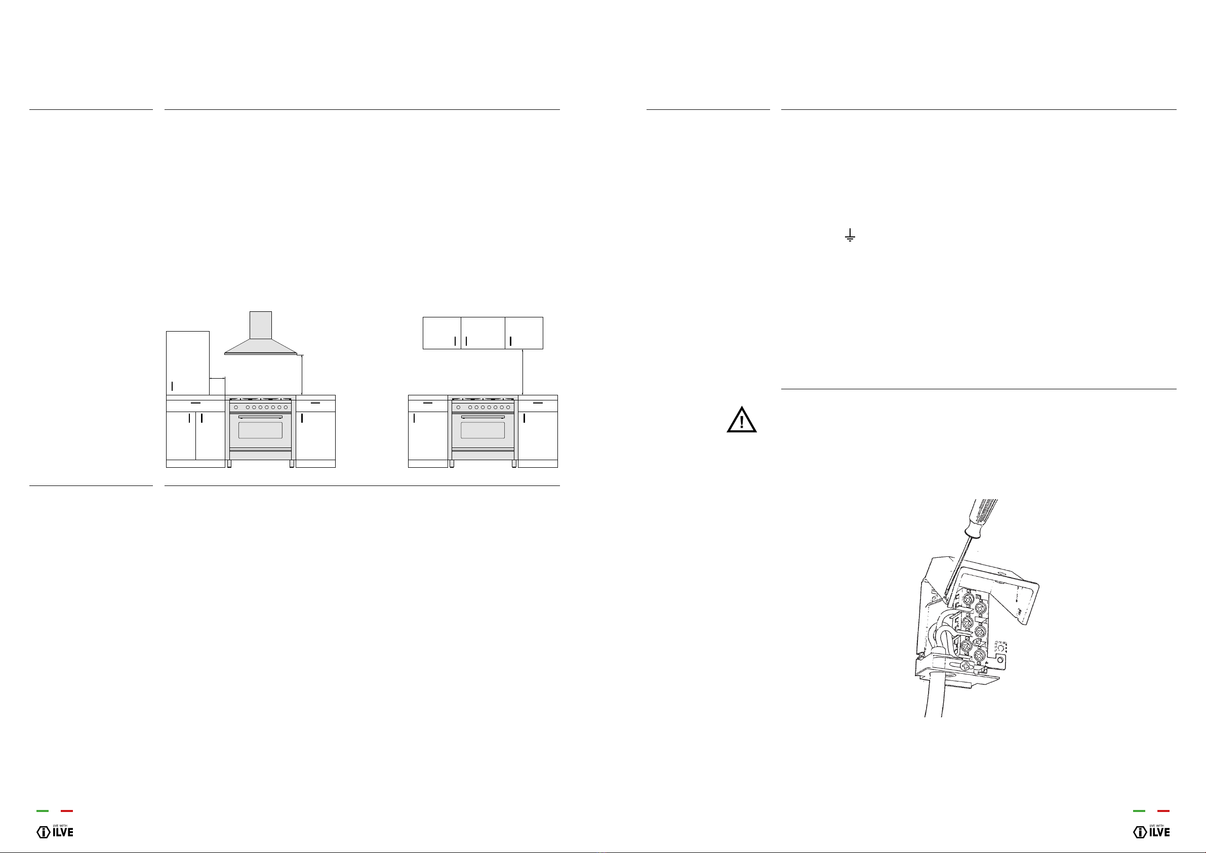
The cooker is factory tted with two chains at the rear of the appliance (one on the
left side and one on the right side) to prevent the appliance from tilting forward.
The installer must connect the chains to the wall, directly behind the chains as low
as possible using a method that suits the wall material and restrains the weight of
the cooker.If the appliance is installed between two cupboards,the installer should
drill a hole on each side of the cupboards, pass the chains through the holes and
anchor the chains within each cupboard.
Important: After xing the chains ensure they are taut and test that the cooker
does not tilt forward or sideways.
Check all connections for gas leaks with soap and water. DO NOT use a naked
ame for detecting leaks. Ignite all burners both individually and concurrently
to ensure correct operation of gas valves, burners and ignition. Turn gas taps to
low ame position and observe stability of the ame for each burner individually
and concurrently. When satised with the hotplate, please instruct the user on the
correct method of operation. In case the appliance fails to operate correctly after
all checks have been carried out, refer to the authorised service provider in your
area.
The ovens are supplied to function as indicated on the plate. Should a change be
necessary you should proceed with the adaptation to another gas as described in
the paragraph “Burner regulation”.
The Data Label is located in the appliance door recess.This appliance is suitable
for Natural Gas and Universal LPG; ensure that the available gas supply matches
the Data Label.
Any adjustment, maintenance, etc. must be performed by an authorized
technician after disconnecting the unit from the mains and from the gas supply.
INSTRUCTIONS
FOR INSTALLATION
Gas connection
Anti-tip device
Before leaving
Adapting for other gas
types
Data label
Replacing the injectors and air adjustment
IMPORTANT: Before carrying out these operations you must disconnect appliance
of electric power supply. After adjustments, the seals must be replaced by the
technician.The air adjustment our burners is not necessary.
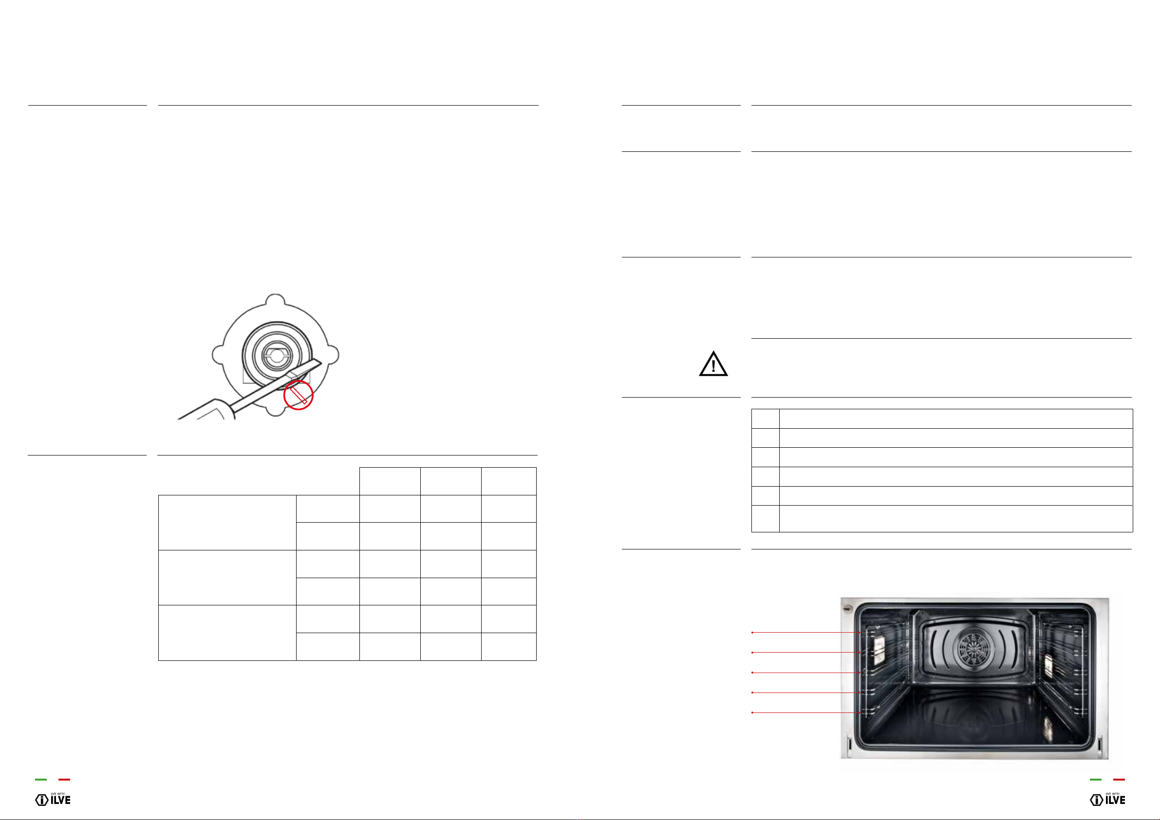
The burners can be adapted to different types of gas by mounting injectors suited
to the user’s gas (see nozzle adjustment table).To do this you need:
1. Extract the pan stands, remove the head an cover of burners
2. With a 7 mm socket spanner unscrew and remove the nozzles from burners
(see g. below)
3. Replace the burner injectors according to the gas to be used (see nozzle
adjustment table)
4. Place the burners in the correct position
ADJUSTMENTS
Adapting for different
types of gas