Küppersbusch GMS 6540.0 E User manual

COD. 04037G1KUPNA2 (04037GB) - 10.07.2008
ODEL: G S 6540.0 E - G S 7551.0 E
Dear Customer,
Thank you for having purchased one of our products.
We are certain that this new, modern, functional and practical appliance, built with the very highest
quality materials, will meet your requirements in the best possible way. This appliance is easy to
use. t is, however, important to thoroughly read the instructions in this handbook in order to obtain
the best results.
These instructions are only valid for the countries of destination, the identification symbols of
which are indicated on the cover of the instruction manual and on the appliance itself.
The manufacturer shall not be held responsible for any damages to persons or property caused
by incorrect installation or use of the appliance.
The Manufacturer shall not be held responsible for any inaccuracies in this handbook due to printing or
transcription errors; the designs in the figures are purely indicative. The Manufacturer also reserves the right
to make any modifications to the products as may be considered necessary or useful, also in the interests
of the user, without jeopardizing the main functional and safety features of the products themselves.
INSTRUCTIONS AND ADVICE FOR THE
USE, INSTALLATION AND AINTENANCE
OF IXED AND GAS FUELLED
BUILT-IN HOT PLATES

1 Ultra rapid gas burner 3100 W
2 Rapid gas burner 2800 W
3 Semirapid gas burner right front 1400 W
4 Semirapid gas burner left back 1750 W
5 Auxiliary gas burner 1000 W
6 Enamelled steel pan support 2F
7 Enamelled steel pan support central
8 Burner n° 1 control knob
9 Burner n° 2 control knob
10 Burner n° 3 control knob
11 Burner n° 4 control knob
12 Burner n° 5 control knob
13 Electric ignition button
Attention: this appliance has been manufactured for domestic use only and it employment by
private person.
DESCRIPTION OF HOBS
TYPES: PCFZD 60 N - PCFZD 60 V TYPES: PCFZD 70 N - PCFZD 70 V
20

1) BURNERS
A diagram is screen-printed above each knob on
the front panel. This diagram indicates to which
burner the knob in question corresponds. After
having opened the gas mains or gas bottle tap, light
the burners as described below:
- manual ignition
Push and turn the knob corresponding to the
required burner in an anticlockwise direction until it
reaches the full on position (large flame fig. 1), then
place a lighted match near the burner.
- Electrical ignition
Push and turn the knob corresponding to the
required burner in an anticlockwise direction until it
reaches the full on position (large flame fig. 1), then
depress and release the ignition button “E”.
- Automatic electrical ignition
Push and turn the knob corresponding to the
required burner in an anticlockwise direction until it
reaches the full on position (large flame fig. 1), then
depress the knob.
- Lighting burners equipped with flame failure
device
The knobs of burners equipped with flame failure
device must be turned in an anticlockwise direction
until they reach the full on position (large flame fig. 1)
and come to a stop. Now depress the knob in
question and repeat the previously indicated
operations.
Keep the knob depressed for about 10 seconds
once the burner has ignited.
HOW TO USE THE BURNERS
Bear in mind the following indications in order to
achieve maximum efficiency with the least possible
gas consumption:
- use adequate pans for each burner (consult the
following table and fig. 2).
- When the pan comes to the boil, set the knob to
the reduced rate position (small flame fig. 1).
- Always place a lid on the pans.
- Use only pan with a flat bottom.
Burners Power ratings Pan Ø in cm
Ultra rapid 3100 24 ÷ 26
Rapid 2800 20 ÷ 22
Semirapid right front 1400 16 ÷ 18
Semirapid left back 1750 16 ÷ 18
Auxiliary 1000 10 ÷ 14
WARNIN S:
- burners with flame failure device may only be
ignited when the relative knob has been set to
the Full on position (large flame fig. 1).
- Matches can be used to ignite the burners in a
blackout.
- Never leave the appliance unattended when
the burners are being used. Make sure there
are no children in the near vicinity. Particularly
make sure that the pan handles are correctly
positioned and keep a chek on foods requiring
oil and grease to cook since these products
can easily catch fire.
- The machine must not be used by people
(including children) with impaired mental or
physical capacities, or without experience of
using electrical devices, unless supervised or
instructed by an expert adult responsible for
their care and safety. Children should not be
allowed to play with the equipment.
- Never use aerosols near the appliance when it
is operating.
- If the built-in hot plate has a lid, any spilt food
should be immediately removed from this
before it is opened. If the appliance has a glass
lid, this could shatter when the hot plate
becomes hot. Always switch off all the burners
before closing the lid.
- Containers wider than the unit are
recommended.
USE
FIG.
1
FIG.
2
21

USE
Notes:
use of a gas cooking appliance produces heat and moisture in the room in which it is installed.
The room must therefore be well ventilated by keeping the natural air vents clear (fig. 3) and by
activating the mechanical aeration device (suction hood or electric fan fig. 4 and fig. 5).
Intensive and lengthy use of the appliance may require additional ventilation. This can be
achieved by opening a window or by increasing the power of the mechanical exhausting system if
installed.
FIG. 3 FIG. 4 FIG. 5
(*) AIR INLET: SEE INSTALLATION CHAPTER (PARA RAPHS 5 AND 6)
22

CLEANING
FIG. 6
IMPORTANT:
always disconnect the appliance from the gas
and electricity mains before carrying out any
cleaning operation.
2) HOT PLATE
Periodically wash the hot plate, the enamelled stell
pan support, the enamelled burner caps “C” and
the burner heads “T” (see fig. 6) with lukewarm
soapy water. Following this, all parts should be
thoroughly rinsed and dried. Never wash them
while they are still warm and never use abrasive
powders. Do not allow vinegar, coffee, milk, salted
water, lemon or tomato juice from remaining in
contact with the enamelled surfaces for long
periods of time.
WARNIN S:
comply with the following instructions, before
remounting the parts:
- check that burner head slots “T” (fig. 6) have
not become clogged by foreign bodies.
- Check that enamelled burner cap “C” (fig. 6)
have correctly positioned on the burner head.
It must be steady.
- The exact position of the pan support is
established by the rounded corners, which
should be set towards the side edge of the
hot plate.
- Do not force the taps if they are difficult open
or close. Contact the technical assistance
service for repairs.
- Don’t use steam jets for the equipment
cleaning.
23

INSTALLATION
A B C D E
4F 553 473 67.5 59.5 100 min.
5F 553 473 67.5 59.5
175 min.
COMPLY WITH THE
DIMENSIONS (in mm)
TECHNICAL INFORMATION FOR
THE INSTALLER
Installation, adjustments of controls and
maintenance must only be carried out by a
qualified engineer.
Incorrect installation may cause damage to
persons, animals or property for which the
Manufacturer shall not be considered responsible.
During the life of the system, the automatic
safety or regulating devices on the appliance
may only be modified by the manufacturer or by
his duly authorized dealer.
3) INSTALLING THE HOT PLATE
Check that the appliance is in a good condition after
having removed the outer packaging and internal
wrappings from around the various loose parts. n
case of doubt, do not use the appliance and contact
qualified personnel.
Never leave the packaging materials (cardboard,
bags, polystyrene foam, nails, etc.) within
children’s reach since they could become
potential sources of danger.
The measurements of the opening made in the top of
the modular cabinet and into which the hot plate will be
installed are indicated in either fig. 7. Always comply
with the measurements given for the hole into which
the appliance will be recessed (see fig. 7 and 8)
.
The appliance belongs to class 3 and is
therefore subject to all the provisions
established by the provisions governing such
appliances.
4) FIXING THE HOT PLATE
The hot plate has a special seal which prevents
liquid from getting into the cabinet. Strictly comply
with the following instructions in order to correctly
apply this seal:
- detach the seals from their backing, checking that
the transparent protection still adheres to the seal
itself.
- Overturn the hot plate and correctly position seal
“E” (fig. 9) under the edge of the hot plate itself, so
that the outer side of the seal perfectly matches
the outer edge of the hot plate. The ends of the
strips must fit together without overlapping.
- Evenly and securely fix the seal to the hot plate,
pressing into place with the fingers and remove
the strip of protective paper from the seal and set
the plate into the hole made in the cabinet.
- Fix the hob with the proper brackets “S” and fit the
prominent part into the porthole “H” on the bottom;
turn the screw “F” until the bracket “S” stick on the
top (fig. 10).
- n order to avoid accidental touch with the
overheating bottom of the hob, during the working,
is necessary to put a wooden insert, fixed by
screws, at a minimum distance of 50 mm from the
top (see fig. 7).
FIG. 7 FIG. 8 FIG. 9 FIG. 10
24

INSTALLATION
IMPORTANT INSTALLATION
INSTRUCTIONS
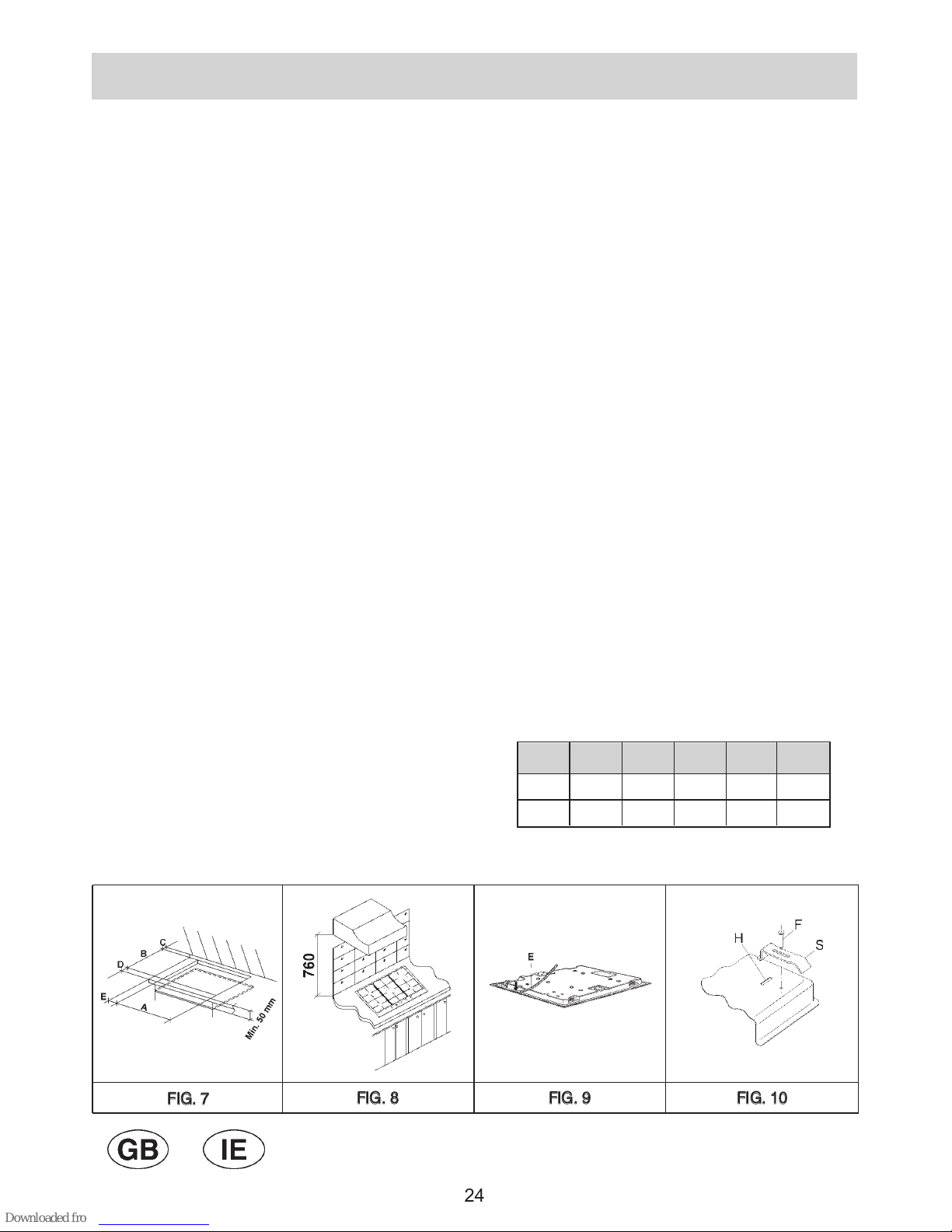
The installer should note that the appliance that
side walls should be no higher than the hot plate
itself. Furthermore, the rear wall, the surfaces
surrounding and adjacent to the appliance must
be able to withstand an overtemperature of 75K.
The adhesive used to stick the plastic laminate
to the cabinet must be able to withstand a
temperature of not less than 150° C otherwise
the laminate could come unstuck. The appliance
must be installed in compliance with BS 6172
1990, BS 5440 part. 2 1989 and BS 6891 1988.
This appliance is not connected to a device able
to dispose of the combustion fumes. It must
therefore be connected in compliance with the
above mentioned installation standards.
Particular care should be paid to the following
provisions governing ventilation and aeration.
5) ROO VENTILATION
To ensure correct operation of the appliance, it is
important to ensure that the room where the hot
plate is installed has sufficient ventilation, as set out
in BS 5440 part 2. 1989. See table below.
Natural air flow must enter directly through
permanent openings in the walls of the room in
question. These must open towards the outside and
possess a minimum section of 100 cm2see fig. 3). t
must be impossible to obstruct these openings.
ndirect ventilation with air drawn from adjacent
rooms is permitted in strict compliance with the
provisions in force.
6) LOCATION AND AERATION
Gas cooking appliances must always dispose of
their combustion fumes through hoods. These must
be connected to flues, chimneys or straight outside
(see fig. 4). f it is not possible to install a hood, an
electric fan can be installed on a window or on a wall
facing outside (see fig. 5). This must be activated at
the same time as the appliance, so long as the
specifications in the provisions in force are strictly
complied with.
7) GAS CONNECTION
Before connecting the appliance, check that the
values on the data label affixed to the underside
of the hot plate correspond to those of the gas
mains in the home.
A label on the appliance indicates the regulating
conditions: type of gas and working pressure.
WARNIN :
a gas hot plate can only be connected by a CORG
Registered engineer.
nstallations should be carried out in accordance with
BS 6891 1988 and must comply with the Gas Safety
Regulations.
All hot plate installations must include an isolation
tap.
AS PRESSURE TEST
Some hot plates models have a test point fitted
under the control panel, to conduct a gas pressure
test proceed as follows:
- turn off the gas supply.
- Remove screw in the pressure test point, place
test gauge connecting tube on test point.
- Fit a burner ring and cap onto burner assembly,
replace control knob onto corresponding control
tap for the burner.
- Turn on gas and ascertain working pressure.
After test, turn off control tap, turn off gas supply,
disconnect test gauge connecting tube. Replace the
test point screw, turn gas back on and test for
soundness. Reassemble the hotplate.
IMPORTANT:
the appliance complies with the provisions of
the following EEC Directives:
- 90/396 + 93/68 regarding gas safety.
25

INSTALLATION
FIG. 11
8) ELECTRICAL CONNECTION
The electrical connections of the appliance
must be carried out in compliance with the
provisions and standards in force.
Before connecting the appliance, check that:
- the electrical capacity of the mains supply and
current sockets suit the maximum power rating of
the appliance (consult the data label applied to the
underside of the hot plate).
- The socket or system has an efficient earth
connection in compliance with the provisions and
standards in force. The manufacturer declines all
responsibility for failing to comply with these
provisions.
When the appliance is connected to the
electricity main by a socket:
- fit a standard plug suited to the load indicated on
the data label to the cable.
- Fit the wires following figure 11, taking care of
respecting the following correspondences:
Letter L (live) = brown wire;
Letter N (neutral) = blue wire;
earth symbol = green - yellow wire.
- The power supply cable must be positioned so
that no part of it is able to reach an
overtemperature of 65K.
- Never use reductions, adapters of shunts for
connection since these could create false contacts
and lead to dangerous overheating.
- The outlet must be accessible after the built-in.
When the appliance is connected straight to the
electricity main:
- install an omnipolar circuit-breaker between the
appliance and the electricity main. This circuit-
breaker should be sized, in compliance with
current installation regulations.
- Remember that the earth wire must not be
interrupted by the circuit-breaker.
- For optimum safety, the electrical connection may
also be protected by a high sensitivity differential
circuit- breaker.
You are strongly advised to fix the relative yellow-
green earth wire to an efficient earthing system.
WARNIN S:
All our appliances are designed and
manufactured in compliance with European
standards EN 60 335-1, EN 60 335-2-6 and
EN 60 335-2-102 plus the relative amendments.
The appliance complies with the provisions of
the following EEC Directives:
- CEE 2004/108/CE regarding to electromagnetic
compatibility.
- CEE 2006/95 regarding electrical safety.
26

INSTALLATION
FIG. 12
9) INSTALLING THE HOT PLATE WITH
THE BATTERY
Check that the appliance is in a good condition after
having removed the outer packaging and internal
wrappings from around the various loose parts. n
case of doubt, do not use the appliance and contact
qualified personnel.
Never leave the packaging materials (cardboard,
bags, polystyrene foam, nails, etc.) within
children’s reach since they could become
potential sources of danger.
The measurements of the opening made in the top of
the modular cabinet and into which the hot plate will be
installed are indicated in either fig. 7. Always comply
with the measurements given for the hole into which
the appliance will be recessed (see fig. 7 and 8)
.
10) FIXING THE HOT PLATE
The hot plate has a special seal which prevents
liquid from infiltrating into the cabinet. Strictly
comply with the following instructions in order to
correctly apply this seal:
- detach the seals from their backing, checking that
the transparent protection still adheres to the seal
itself.
- Overturn the hot plate and correctly position seal
“E” (fig. 9) under the edge of the hot plate itself, so
that the outer side of the seal perfectly matches
the outer perimetral edge of the hot plate. The
ends of the strips must fit together without
overlapping.
- Unscrew the ignition cap “T” (see fig. 12) and fit a
1.5 V battery (not included in the appliance) with
the positive “+” polarity turn inside. Rescrew the
cap.
- Evenly and securely fix the seal to the hot plate,
pressing into place with the fingers and remove
the strip of protective paper from the seal and set
the plate into the hole made in the cabinet.
- Fix the hob with the proper brackets “S” and fit the
prominent part into the porthole “H” on the bottom;
turn the screw “F” until the bracket “S” stick on the
top (fig. 10).
- n order to avoid accidental touch with the
overheating bottom of the hob, during the working,
is necessary to put a wooden insert, fixed by
screws, at a minimum distance of 50 mm from the
top (see fig. 7).
27

FIG. 13
ADJUST ENTS
Always disconnect the appliance from the
electricity main before making any adjustments.
All seals must be replaced by the technician at
the end of any adjustments or regulations.
Our burners do not require primary air
adjustment.
11) TAPS
“Reduced rate” adjustment
- Switch on the burner and turn the relative knob to
the “Reduced rate” position (small flame fig.1).
- Remove knob “M” (fig. 13) of the tap, which is
simply pressed on to its rod.
- nsert a small screwdriver “D” into hole “C” (fig. 13)
and turn the throttle screw to the right or left until
the burner flame has been adequately regulated to
the “Reduced rate” position.
Check that the flame does not go out when the
knob is sharply switched from the “Full on” to the
“Reduced rate” position.
It is understood that only burners operating
with 20 or Town gas should be subjected to
the above mentioned adjustments. The screw
must be fully locked when the burners operate
with 30 (turn clockwise).
28

BURNER ARRANGE ENT ON THE HOT PLATE
GB/IE/OTHER ARKETS
FIG. 14
SE IRAPID
RIGHT FRONT
BURNERS
N°
DESCRIPTION
GAS
mbar
NOR AL
RATE
g/h l/h
INJECTOR
DIA ETER
1/100 mm
NO INAL HEAT
INPUT (W)
in. ax.
1
3
2
G 30 -
BUTANE
G 31 - PROPANE
G 20 -
NATURAL
ULTRA RAPID
RAPID
28 - 30
37
20
225
222 295
204
200 267
102
100 133
90
90
121 Y
83
83
117 S
58
58
85 Y
1400
1400
1400
800
800
800
500
500
500
3100
3100
3100
2800
2800
2800
1400
1400
1400
4127
125 167
65
65
97 Z
500
500
500
1750
1750
1750
5AUXILIARY
73
71 95
50
50
72 X
400
400
400
1000
1000
1000
NOR AL
PRESSURE
28 - 30
37
20
28 - 30
37
20
28 - 30
37
20
28 - 30
37
20
CONVERSIONS
SE IRAPID
LEFT BACK
12) REPLACING THE INJECTORS
The burners can be adapted to different types of
gas by mounting injectors suited to the type of gas
in question. To do this, first remove the burner tops
using a wrench “B”. Now unscrew injector “A” (see
fig. 14) and fit a injector corresponding to the
utilized type of gas in its place.
t is advisable to strongly tighten the injector in
place.
After the injectors have been replaced, the
burners must be regulated as explained in
paragraphs 11. The technician must reset any
seals on the regulating or pre-regulating devices.
The envelope with the injectors and the labels can
be included in the kit, or at disposal to the
authorized customer Service Centre.
For the sake of convenience, the nominal rate table
also lists the heat inputs of the burners, the
diameter of the injectors and the working pressures
of the various types of gas.
G 30 -
BUTANE
G 31 - PROPANE
G 20 -
NATURAL
G 30 -
BUTANE
G 31 - PROPANE
G 20 -
NATURAL
G 30 -
BUTANE
G 31 - PROPANE
G 20 -
NATURAL
G 30 -
BUTANE
G 31 - PROPANE
G 20 -
NATURAL
29

SERVICING
FIG. 18 FIG. 19 FIG. 20
FIG. 15 FIG. 16 FIG. 17
Always disconnect the appliance from the
electricity and gas mains before proceeding
with any servicing operation.
13) REPLACING HOT PLATE PARTS
Replacement of the components housed inside
the appliance: remove the trivets and the burners
from the upper part of the working table; remove
the fixing screws "V" of the burner (fig. 15) and the
knobs fixed by pressure with the hans, in order to
take off the appliance.
After having carried out the above listed operations,
the burners (fig. 16), taps (fig. 17) and electrical
components can all be replaced (fig. 18).
NB: the ignition bar must be removed before
replacing the taps in appliances with automatic
ignition systems.
t is advisable to change seal “D” whenever a tap is
replaced to ensure a perfect tightness.
reasing the taps (see fig. 19 - 20)
f a tap becomes stiff to operate, it must be
immediately greased in compliance with the
following instructions:
- remove the tap.
- Clean the cone and its housing using a cloth
soaked in diluent.
- Lightly spread the cone with the relative grease.
- Fit the cone back in place, operate it several times
and then remove it again. Eliminate any excess
grease and check that the gas ducts have not
become clogged.
- Fit all parts back in place, complying with the
demounting order in reverse.
- The tight closure test must be done using a foamy
liquid. The use of the flame is prohibited.
To facilitate the servicing technician’s task, here is a
chart with the types and sections of the powering
cables and the ratings of the electrical components.
30

SERVICING
FIG. 21
14) REPLACING THE BATTERY
To change the battery (see fig. 21) comply with
following instructions:
- unscrew cap “T” and remove exausty battery.
- nsert a 1.5 V new battery. The positive polarity
“+” is turn over inside.
- Rescrew the cap “T”.
- Re-assembly all the movable parts.
WARNIN :
the batteries contain a dangerous material for
our ambient. Always put them in a separate
and safe container.
If you eliminate your appliance, remember to
take off the battery.
31

SERVICING
FIG. 22
Gas hot plate H05 RR - F Section 3 x 0.75 mm2
TYPE OF TYPE OF SINGLE - PHASE
HOT PLATE CABLE POWER SUPPLY
CABLE TYPES AND SECTIONS
ATTENTION!!!
If the power supply cable is replaced, the installer should leave the ground wire longer than the
phase conductors (fig. 22) and comply with the recommendations given in paragraph 8.
32

4 BURNERS (60)
CATEGORY = 2H3+
G 30 - BUTANE = 28 - 30 mbar
G 31 - PROPANE = 37 mbar
G 20 - NATURAL = 20 mbar
Σ Qn LPG Gas Rate = 6.95 kW
Σ Qn LPG Gas Rate = 506 g/h
Voltage = 230 - 240 V
~
Frequency = 50/60 Hz
5 BURNERS (70)
CATEGORY = 2H3+
G 30 - BUTANE = 28 - 30 mbar
G 31 - PROPANE = 37 mbar
G 20 - NATURAL = 20 mbar
Σ Qn LPG Gas Rate = 10.05 kW
Σ Qn LPG Gas Rate = 731 g/h
Voltage = 230 - 240 V
~
Frequency = 50/60 Hz
4 BURNERS (60)
WITH BATTERY
CATEGORY = 2H3+
G 30 - BUTANE = 28 - 30 mbar
G 31 - PROPANE = 37 mbar
G 20 - NATURAL = 20 mbar
Σ Qn LPG Gas Rate = 6.95 kW
Σ Qn LPG Gas Rate = 506 g/h
Voltage = 1.5 V DC
5 BURNERS (70)
WHIT BATTERY
CATEGORY = 2H3+
G 30 - BUTANE = 28 - 30 mbar
G 31 - PROPANE = 37 mbar
G 20 - NATURAL = 20 mbar
Σ Qn LPG Gas Rate = 10.05 kW
Σ Qn LPG Gas Rate = 731 g/h
Voltage = 1.5 V DC
TECHNICAL DATA ON THE DATA LABEL
GB/IE/OTHER ARKETS
33

TECHNICAL DATA FOR THE APPLIANCE
GAS REGULATION
34

35
Before leaving the factory, this appliance will have been tested and regulated by expert and specialized
personnel in order to guarantee the best performances.
Any repairs or adjustments which may be subsequently required may only be carried out by qualified
personnel with the utmost care and attention.
For this reason, always contact your Dealer or our nearest After Sales Service Center whenever repairs
or adjustments are required, specifying the type of fault and the model of the appliance in your
possession.
Please also note that genuine spare parts are only available from our After Sales Service Centers and
authorized retail outlets.
The above data are printed on the data label put on the inferior part of the appliance and on the packing
label.
The above informations give to the technical assistant the possibility to get fit spare parts and a heaven-
sent intervention. We suggest to fill the table below.
MARK: ........................................................................
MODEL: ......................................................................
SERIES: ......................................................................
TECHNICAL ASSISTANCE AND SPARE PARTS

36
Other manuals for GMS 6540.0 E
1
This manual suits for next models
1
Other Küppersbusch Cooktop manuals

Küppersbusch
Küppersbusch EKWE User manual

Küppersbusch
Küppersbusch EKIF9960.1 Operation manual

Küppersbusch
Küppersbusch EKI 407.0M User manual

Küppersbusch
Küppersbusch EKS 604.2 User manual

Küppersbusch
Küppersbusch GKS 324.0 User manual

Küppersbusch
Küppersbusch ETS 3720. 0 Manual

Küppersbusch
Küppersbusch GMS 6540.0 E-UL User manual

Küppersbusch
Küppersbusch KI8800.0GR Operation manual

Küppersbusch
Küppersbusch KI9800.0SF User manual

Küppersbusch
Küppersbusch EKI3920.1ED Operation manual