ILLUMINO IGNIS SMARTWIRE User manual

Page 0
Issue: 1.4 Author: JPB Date: 18/1/2013
Quickstart Guide

Page 1
Issue: 1.4 Author: JPB Date: 18/1/2013
Overview
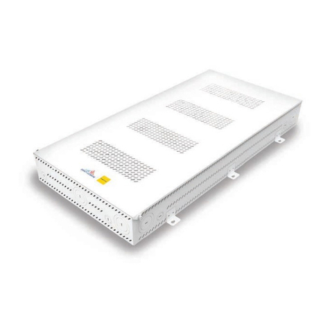
The SMARTWIRE is an intelligent 2 wire panel that is available in 2, 4 or 8 zone
sizes.
It can have up to 15 devices per zone.
The system uses an intelligent sounder flasher base, and SMARTWIRE smoke or
heat detectors.
Special 2 wire call points, sounders, and interface units can be fitted to the
zone circuits
There are also 2 conventional sounder circuits that will run any conventional
sounder or flasher.

Page 2
Issue: 1.4 Author: JPB Date: 18/1/2013
Planning the System
SMARTWIRE has 2, 4 or 8 zones.
It can have up to 15 devices in each zone
The total system load is 64 sounder flashers.
Choosing the cabling method
A SMARTWIRE system can be wired as individual radial circuits, or as a loop.
The default configuration is radial circuits.
To alter the panel for loop wiring:-
1. Enter access code 123
2. Press enter for user menu
3. Select option 5 (engineer)
4. Enter code 369 for engineer menu
5. Press next for page 2 of engineer menu
6. Select option 6 (Misc)
7. Select option 3 (Topology)
8. Press Prev/Next to select loop & press enter to save.
The panel is now configured for loop wiring. The loop should be connected to
zone 1 and zone 2 terminals.
Note that when wiring as a loop, the first device on each zone should be a call
point, with the Short circuit isolator connected.

Page 3
Issue: 1.4 Author: JPB Date: 18/1/2013
Connections
The SMARTWIRE sounder base
Terminal
Label
Wire Colour Description
1 + Brown Loop In +ve
2
-
Blue
Loop In
-
ve
3 Earth
Green/Yellow
Loop earth screen (In & Out)
4
-
Blue
Loop Out
–
ve
5 + Brown Loop Out +ve
Call Point
(See instructions supplied with call point)
5
2
3
4
1

Page 4
Issue: 1.4 Author: JPB Date: 18/1/2013
Setting the device configuration switches.
All devices will need to have their zone & ID switches set as described below.
Switch 8 will depend on the type of the device.
Zone Setting
Zone Number Switch 5 Switch 6 Switch 7
1 ON ON ON
2 OFF ON ON
3 ON OFF ON
4
OFF
OFF
ON
5 ON ON OFF
6 OFF ON OFF
7 ON OFF OFF
8 OFF OFF OFF
Select the zone the device is fitted to (1 to 8). Each item on a zone has the
same zone setting
ID Setting
ID
Number
Sw 1 Sw 2 Sw 3 Sw 4
ID
Number
Sw 1 Sw 2 Sw 3 Sw 4
1 OFF ON ON ON
9 OFF ON ON OFF
2 ON OFF ON ON
10 ON OFF ON OFF
3 OFF OFF ON ON
11 OFF OFF ON OFF
4 ON ON OFF ON
12 ON ON OFF OFF
5
OFF
ON
OFF
ON
13
OFF
ON
OFF
OFF
6 ON OFF OFF ON
14 ON OFF OFF OFF
7 OFF OFF OFF ON
15 OFF OFF OFF OFF
8 ON ON ON OFF
Give the device a unique zone ID number between 1 & 15. Each item on a zone
has a different ID setting.
Settings for switch 8
Detector Type Switch 8 Position
SMARTWIRE SOUNDER FLASHER BASE –SMOKE
DETECTOR
OFF
SMARTWIRE SOUNDER FLASHER BASE –HEAT ON

Page 5
Issue: 1.4 Author: JPB Date: 18/1/2013
DETECTOR
SMARTWIRE CALL POINT ON
SMARTWIRE
SOUNDER
ON
I/O INTERFACE ON
SMARTWIRE Menu Layout
User Menu
In the user menu, you can view information for Zone contents or device status,
or look at the event log. The clock can also be adjusted from here.
Any Editing is done in the Engineer Menu.
Engineer menu
Main Menu
1.Clock 4. Device
2.Zone 5. Engineer
3.Logs
Engineer Menu 1
1. Configure Zones
2. Panel/Zone Text
3. ID Device >
Engineer Menu 2
4. Alarm Verify
5. Config Alarms
6. Misc <
Verification
1. Verify Time
2. Choose Devices
Panel/Zone Text
1. Panel
2. Zones
Misc Settings
1. Language
2. Version
3. Topology 6: Reset
Alarm Operation
1. Fire Relay
2. Interfaces
3. Alarm Tone

Page 6
Issue: 1.4 Author: JPB Date: 18/1/2013
Learning the Zone contents
When devices are connected to a blank panel, the panel will report new
devices found, and display “press enter to configure”
Pressing enter will configure the zones.
If the panel is not blank, the configuration will need to be started manually
1. Press enter to access the user menu
2. If the panel asks for a code, type 123
3. Select option 5 (Engineer)
4. If the panel asks for a code enter the engineer code 369
5. Select option 1 (Configure Zones)
The panel will take approx 2 minutes to check & configure the zones.
The panel allows the Zone text labels to be programmed during this time. Press
enter to jump to the programming screen, or wait until the configuration is
finished.
Sometimes it is more convenient to configure the system a zone at a time. (To
get one zone running first, then move onto the next one)
If the system is being configured a zone at a time, these steps will need to be
repeated each time a new zone is added.

Page 7
Issue: 1.4 Author: JPB Date: 18/1/2013
Panel reports Zoning fault after configuration
On the SMARTWIRE Panel, all devices on a circuit need the configuration
switches 5,6 & 7 to be the correct setting for the zone they are connected to.
Zone Number Switch 5 Switch 6 Switch 7
1
ON
ON
ON
2 OFF ON ON
3 ON OFF ON
4 OFF OFF ON
5 ON ON OFF
6
OFF
ON
OFF
7 ON OFF OFF
8 OFF OFF OFF
If any device has the wrong setting for the zone it is connected to, the panel
will list it as a zone fault after the configuration has finished.
The panel lets you scroll through any faults, and lights the Flasher or LED of the
currently displayed fault. This makes identifying the device on site easier.
These should be all be corrected and then the panel reconfigured before
proceeding.

Page 8
Issue: 1.4 Author: JPB Date: 18/1/2013
Checking Zone contents
From the system normal screen, Press enter to display the user menu, then
select option 2
The panel displays the number of devices fitted to each zone. Check this
number is as expected.
Pressing the next button displays a detailed contents for each zone.
On this screen the panel shows the number of sounders, smoke detectors,
heat detectors, call points etc.
NOTE: A sounder base with a detector fitted is counted as 2 devices (a sounder
and a detector)
While displaying the detailed contents, the panel will turn on the LED or flasher
of all devices on the zone. This allows commissioning engineers to verify the
actual location of the content of each zone
Z01: 03 Z02: 05
Z03: 04 Z04: 07
Z05: 00 Z06: 00
Z07: 00 Z08: 00
Zone 1 Contents
Smoke 01|SND 02
Heat 01|I/O 00
MCP 01|ERR 00

Page 9
Issue: 1.4 Author: JPB Date: 18/1/2013
Editing Panel Name.
The SMARTWIRE panel allows a text label to be added to the zone, and to the
device. It also allows a 2 x 20 character name to be entered. This name will
replace the “SMARTWIRE”banner on the system normal screen.
To edit the Panel Name:-
1. Press enter to access the user menu
2. If the panel asks for a code, type 123
3. Select option 5 (Engineer)
4. If the panel asks for a code enter the engineer code 369
5. Select option 2 (Panel/Zone Text)
6. Select option 1 (Panel Name)
7. Type in the first line of the panel name
8. Press enter to select the next line
9. Enter text for second line, or leave blank
10.Press enter to save the name.

Page 10
Issue: 1.4 Author: JPB Date: 18/1/2013
Choosing to use zone labels, address labels, or both.
The SMARTWIRE panel has been designed to be flexible in the use of which
labels are added. The table below gives a brief summary of the pros & cons of
each option.
Labels
Pros
Cons
None Simplest set-up (No text
entry)
Panel just gives a numerical
indication of an event (e.g. zone 3,
ID 6)
Would need a “zone chart”to
identify location
Zone only Max 8 labels to enter
Gives description of zone
where event occurred
Would still need a “Device chart”to
find exact location of event
Device only
Has a 20 character
description for each device
Device description may not be
useful to people not familiar to
building (Eg fire fighters)
Zone &
Device
Extra zone label help avoid
squeezing “zone location”
into the device name. (eg
“1st FL.......”)
During an event, the zone
& device labels are
alternated on the screen.
More text entry –takes a bit longer
to set up.
To edit a zone label:-
1. Press enter to access the user menu
2. If the panel asks for a code, type 123
3. Select option 5 (Engineer)
4. If the panel asks for a code enter the engineer code 369
5. Select option 2 (Panel/Zone Text)
6. Select option 2 (Zone)
7. Press prev/next to select desired zone
8. Press enter to select cursor
9. Enter text
10.Press Enter to save text
11.Press next to select next zone to be edited.

Page 11
Issue: 1.4 Author: JPB Date: 18/1/2013
To edit a Device Label:-
1. Press enter to access the user menu
2. If the panel asks for a code, type 123
3. Select option 5 (Engineer)
4. If the panel asks for a code enter the engineer code 369
5. Select option 3 (Device ID)
6. Press prev/next to select desired device
7. Press enter to select cursor
8. Enter text
9. Press next to select next device to be edited.
To jump to a specific device (Eg to change the description of a device on a
system that has already been configured):-
From the Device ID screen, press 1
The panel prompts for a zone and ID. Enter the zone & ID of the device to be
edited.

Page 12
Issue: 1.4 Author: JPB Date: 18/1/2013
Configuring the sounder flasher bases.
The SMARTWIRE panel allows the sounder, the flasher, or both to be turned
off for any sounder flasher base as required
(Note that with the panel will still light the flasher for engineering functions,
even if the flasher has been turned off).
To turn off a sounder or flasher on a base:-
1. Press enter to access the user menu (enter code 123 if requested)
2. Select option 5 –Engineer. (enter code 369 if requested)
3. Select option 3 –ID Device.
4. Press Prev or Next to scroll to the device to be changed.
5. Press button 7 (S for Sounder)
6. The icon in the top right hand corner will cycle between :-
a. Sounder & flasher
b. Sounder Only
c. Flasher Only
d. Base only (no sounder or flasher)
7. When the desired option is set, press Prev/Next to set another device, or
cancel to exit the set-up screen

Page 13
Issue: 1.4 Author: JPB Date: 18/1/2013
Alarm Verification.
The SMARTWIRE panel allows alarm verification to be applied to any smoke
detector on the system.
Alarm Verification is used to help filter out unwanted alarms caused by
transient smoke or smoke like phenomenon, such as cooking fumes, or steam
from a shower. It can set off a local intermittent warning, before it sets off a
full alarm. If the alarm clears within the set time, the panel will reset itself. This
can help prevent unwanted building evacuations.
To set alarm verification:-
1. Press enter to access the user menu (enter code 123 if requested)
2. Select option 5 –Engineer. (enter code 369 if requested)
3. Select option 4 –Alarm Verify
4. Select option 1 –verification time
5. Choose the required verification time (between 30 seconds to 3 mins 45
seconds in 15 second increments)
6. Press enter to confirm the verification time
7. Press 2 to choose the devices that will use alarm verification
8. Press Prev/Next to scroll to the required device.
9. Press button 8 (V for Verify). The panel shows V in the top right hand
corner to show that verification is selected for that device.
10.Press Prev/ Next to select another device to verify, or press cancel to exit
the menu.

Page 14
Issue: 1.4 Author: JPB Date: 18/1/2013
Finding a device.
If the system has been set up by a 3rd party, the exact Device locations are not
always available.
The SMARTWIRE panel allows the engineer to turn on the LED / Flashers of any
device.
Go to ID Device screen.
Scroll to the device to find
Press 4 (= I for indicator) to turn on a call point`s LED or a sounder bases
flasher.
For sounders, these can be turned on by pressing the general test button
Press the button again to toggle the function off, or press cancel to exit the
screen (this also turns it off)
Table of contents
Popular Control Panel manuals by other brands
Honeywell
Honeywell Domonial CMI Series Installer manual
INIM Electronics
INIM Electronics PREVIDIA MAX System guide
AP
AP ARTON-08F Operational manual
AdvanteX
AdvanteX VCOM AX20-A1 installation manual
Pego
Pego ECP300 EXPERT VD Series Use and maintenance manual
jablotron
jablotron JA-82K OASiS installation manual
DMP Electronics
DMP Electronics XR200 installation guide

XIM Technologies
XIM Technologies C3-X60 Series installation guide

Plymovent
Plymovent CONTROLPRO/DILUTER installation manual

Texecom
Texecom Premier 412 user manual
Intermatic
Intermatic EMPS3IN installation guide
EDM
EDM Solution Ultima 844 installation manual
