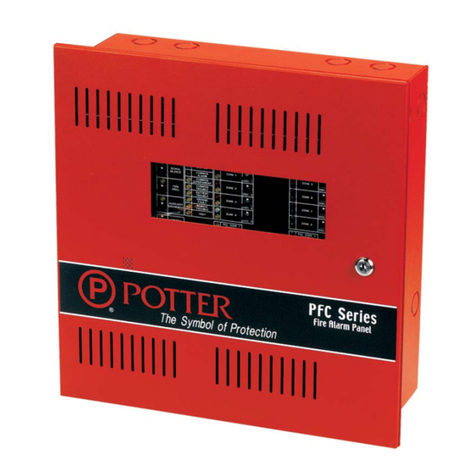
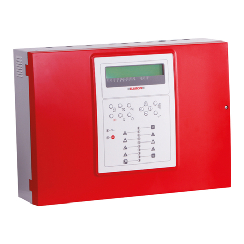
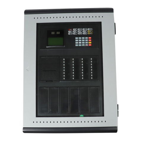
Potter PFC-100RC User manual

2081 CRAIG ROAD • P.O. BOX 28480 • ST. LOUIS, MO. 63146-4161
(800) 325-3936 • (314) 878-4321 • FAX (314) 878-7264
www.pottersignal.com
ALL SPECIFICATIONS SUBJECT TO REVISION
INSTALLATION, OPERATION
AND INSTRUCTION MANUAL
PFC-100RC
FIRE CONTROL PANEL
FOR
RELEASING DEVICE SERVICE
Manual #5403524 - Rev M
3/03

2
PFC-100RC • 5403524-REV M • 3/03
Potter Electric Signal Company
2081 Craig Road • P.O. Box 28480 • St. Louis, MO 63146-4161 • (314) 878-4321 • (800) 325-3936
WARRANTY INFORMATION
The essential purpose of any sale or contract for sale of any of the products listed in the
POTTER catalog or price list is the furnishing of that product. It is expressly understood
that in furnishing said product, POTTER does not agree to insure the Purchaser against
any losses the Purchaser may incur, even if resulting from the malfunction of said product.
POTTER warrants that the equipment herein shall conform to said descriptions as to all
affirmation of fact and shall be free from defects of manufacture, labeling and packaging
for a period of one (1), three (3), or five (5) year'(s), depending on the product, from the
invoice date to the original purchaser, provided that representative samples are returned to
POTTER for inspection. The product warranty period is stated on the exterior of the prod-
uct package. Upon a determination by POTTER that a product is not as warranted, POT-
TER shall, at its exclusive option, replace or repair said defective product or parts thereof
at its own expense except that Purchaser shall pay all shipping, insurance and similar
charges incurred in connection with the replacement of the defective product or parts
thereof. This Warranty is void in the case of abuse, misuse, abnormal usage, faulty instal-
lation or repair by unauthorized persons, or if for any other reason POTTER determines
that said product is not operating properly as a result of causes other than defective manu-
facture, labeling or packaging.
THE AFORESAID WARRANTY IS EXPRESSLY MADE IN LIEU OF ANY OTHER WAR-
RANTIES, EXPRESSED OR IMPLIED, IT BEING UNDERSTOOD THAT ALL SUCH
OTHER WARRANTIES, EXPRESSED OR IMPLIED, INCLUDING THE WARRANTIES OF
MERCHANTABILITY AND FITNESS FOR PARTICULAR PURPOSE ARE HEREBY EX-
PRESSLY EXCLUDED. IN NO EVENT SHALL POTTER BE LIABLE TO PURCHASER
FOR ANY DIRECT, COLLATERAL, INCIDENTAL OR CONSEQUENTIAL DAMAGES IN
CONNECTION WITH PURCHASER’S USE OF ANY OF THE PRODUCTS LISTED
HEREIN, OR FOR ANY OTHER CAUSE WHATSOEVER RELATING TO THE SAID
PRODUCTS. NEITHER POTTER NOR ITS REPRESENTATIVES SHALL BE LIABLE TO
THE PURCHASER OR ANYONE ELSE FOR ANY LIABILITY, CLAIM, LOSS, DAMAGE
OR EXPENSE OF ANY KIND, OR DIRECT COLLATERAL, INCIDENTAL OR CONSE-
QUENTIAL DAMAGES RELATIVE TO OR ARISING FROM OR CAUSED DIRECTLY OR
INDIRECTLY BY SAID PRODUCTS OR THE USE THEREOF OR ANY DEFICIENCY,
DEFECT OR INADEQUACY OF THE SAID PRODUCTS. IT IS EXPRESSLY AGREED
THAT PURCHASER’S EXCLUSIVE REMEDY FOR ANY CAUSE OF ACTION RELATING
TO THE PURCHASE AND/OR USE OF ANY OF THE PRODUCTS LISTED HEREIN
FROM POTTER SHALL BE FOR DAMAGES, AND POTTER'S LIABILITY FOR ANY AND
ALL LOSSES OR DAMAGES RESULTING FROM ANY CAUSE WHATSOEVER, IN-
CLUDING NEGLIGENCE, OR OTHER FAULT, SHALL IN NO EVENT EXCEED THE
PURCHASE PRICE OF THE PRODUCT IN RESPECT TO WHICH THE CLAIM IS MADE,
OR AT THE ELECTION OF POTTER, THE RESTORATION OR REPLACEMENT OR
REPAIR OF SUCH PRODUCT.

3
PFC-100RC • 5403524-REV M • 3/03
Contents
General Description ............................................................................................................................................................................ 4
System Features ................................................................................................................................................................................... 4
Ordering Information .......................................................................................................................................................................... 4
Specifications ...................................................................................................................................................................................... 5
Housing ........................................................................................................................................................................................ 5
Power ............................................................................................................................................................................................ 5
Termination .................................................................................................................................................................................. 5
Temperature Range ...................................................................................................................................................................... 5
Approvals and Listings ................................................................................................................................................................ 5
Service Use................................................................................................................................................................................... 5
Visual Indicators .......................................................................................................................................................................... 5
Diagnostic Indicators ................................................................................................................................................................... 5
Initiating Device Circuit ............................................................................................................................................................... 6
Dry Contact Initiating Device Circuit .......................................................................................................................................... 6
Supervisory Circuit ...................................................................................................................................................................... 6
Indicating Appliance Circuit ........................................................................................................................................................ 6
Releasing Circuit .......................................................................................................................................................................... 6
Audible Indicator ......................................................................................................................................................................... 6
Control Switches .......................................................................................................................................................................... 6
Auxiliary Power Outputs .............................................................................................................................................................. 7
Auxiliary Contact Outputs ........................................................................................................................................................... 7
Basic Operation ................................................................................................................................................................................... 7
Alarm Condition ........................................................................................................................................................................... 7
Supervisory Condition ................................................................................................................................................................. 7
Trouble Conditions ...................................................................................................................................................................... 7
System Trouble Indications ......................................................................................................................................................... 7
To Silence an Alarm or Trouble Condition ................................................................................................................................. 8
To Reset an Alarm Condition ...................................................................................................................................................... 8
Selecting Style D (Class A) or Style B (Class B) Initiating Device Circuit Operation ...................................................................... 8
Selecting Releasing Circuit Time Delay ............................................................................................................................................. 8
Selecting Trouble Relays following Trouble Buzzer.......................................................................................................................... 8
Selecting Releasing Time .................................................................................................................................................................... 8
Selecting Local Buzzer to Sound Under Alarm Conditions ............................................................................................................... 8
Installation ........................................................................................................................................................................................... 9
Installation of Bezel for Semi-flush Installations ............................................................................................................................... 9
Circuit Breakers ................................................................................................................................................................................. 10
Resetting Circuit Breakers ................................................................................................................................................................ 10
Inactive Circuits ................................................................................................................................................................................ 10
Battery Requirements ........................................................................................................................................................................ 10
Battery Size Requirements ................................................................................................................................................................ 10
Table 1, Current Requirements ......................................................................................................................................................... 11
Table 2, Secondary Power Supply Requirements ............................................................................................................................. 11
Table 3, Battery Calculation Table ................................................................................................................................................... 11
Test Procedure ................................................................................................................................................................................... 12
Connection Drawing for PFC-100RC (Identifier "A") ..................................................................................................................... 13
Location Drawing of Diagnostic LEDs and Jumpers on Main Circuit Board Module .................................................................... 14
Front Panel ........................................................................................................................................................................................ 15
Typical 4-Wire Detector Connection Drawing ................................................................................................................................. 15
Typical 2-Wire Detector Connection Drawing ................................................................................................................................. 16
2-Wire Smoke Detector Compatibility Data ..................................................................................................................................... 17
Automatic Water Control Valves Compatibility Data ...................................................................................................................... 18
Fixed Extinguishing Systems Compatibility Data ............................................................................................................................ 18
Alarm Indicating Appliance Compatibility Data .............................................................................................................................. 18
Wire Routing for PFC-100RC .......................................................................................................................................................... 19
4
PFC-100RC • 5403524-REV M • 3/03
GENERAL DESCRIPTION
This single zone fire control panel is designed to meet the requirements of Underwriters Laboratories Standard 864 for Local
Control Units for Releasing Device Service, and to be compatible with NFPA-72, NFPA-12, NFPA-12A, NFPA-12B,NFPA-13
and NFPA-17.
SYSTEM FEATURES
• One Initiating Device Circuit, Selectable Style D (Class A) or Style B (Class B)
• One Style B (Class B) Dry Contact Initiating Device Circuit
• One Style Y (Class B) Indicating Appliance Circuit
• One Style Y (Class B) Releasing Circuit (Single Zone or Dry Contact Initiating Device Circuit)
• One Style B (Class B) Supervisory Circuit
• SPST (N.O.) (Form A) Auxiliary Trouble Contacts
• SPDT (Form C) Auxiliary Alarm Contacts
• 24VDC 200mA Auxiliary Power Output
• All Power Limited Circuits
• Alarm/Trouble Silence Switch
• Dry Contact Initiating Device Circuit
• Built in Trouble Buzzer
• 24 or 90 Hr Standby Available
• Compatible with 2 or 4-wire Detectors (Maximum 25 - 0.1mA Detectors)
ORDERING INFORMATION
Model Description Stock No.
PFC-100RC Single Zone Releasing Panel (White Cabinet) 3005900
PFC-100RC Single Zone Releasing Panel (Red Cabinet) 3005902
BT-40 Battery, 12 Volt, 4.0AH (24 hr. standby, 2 reqd.) 5130092
BT-80 Battery, 12 Volt, 8.0AH (60 hr. standby, 2 reqd.) 5130084
BT-120 Battery, 12 Volt, 12.0AH (90 hr. standby, 2 reqd.) 5130090
Spare or Replacement Parts:
Main Circuit Board Module for PFC-100RC 3005910
EOL Resistor 5.1K 5080600
EOL Resistor and Diode Assembly for Releasing Circuit 3005012
Transformer 5270184

5
PFC-100RC • 5403524-REV M • 3/03
SPECIFICATIONS
HOUSING
Type: General purpose, indoor, steel enclosure with hinged removable cover and key lock
Size: 18 1/2" x 14 1/4" x 4 3/4"
Finish: Baked enamel, off-white with grey trim and red logo. Available in other colors and private labeling as required
by users (consult factory).
Knockouts: 8 combination 1/2"-3/4" knockouts. Two on each side, top and back
Option: Bezel for semi-flush mounting in a 4" wall
POWER
• 117V AC, single phase, 60 Hz, 100 VA
• Standby - 60mA at 24VDC (see “Battery Requirements”)
• Alarm - 130mA at 24VDC
TERMINATION
AC power, 3 #18 AWG wire leads are supplied with wire nuts. Battery leads are supplied with quick disconnect terminals. All
other terminals are barrier type screw terminals capable of handling #14 AWG conductors .
TEMPERATURE RANGE
32°F to 120°F / 0°C to 49°C
APPROVALS AND LISTINGS
SERVICE USE
NFPA 12 Carbon Dioxide Extinguishing Systems
NFPA 12A Halon 1301 Fire Extinguishing Systems
NFPA 12B Halon 1211 Fire Extinguishing Systems
NFPA 13 Installation of Sprinkler Systems
NFPA 17 Dry Chemical Extinguishing Systems
NFPA 72 National Fire Alarm Code (Local: A, M, SS, service type; NC signaling type)
VISUAL INDICATORS (With door closed)
AC: Green LED indicates AC voltage reaches above 102 volts input.
Alarm: Red LED indicates an alarm condition.
System Trouble: Yellow LED indicates a trouble condition. Possible conditions are Ground Fault, Initiation Device Circuit
Trouble, Supervisory Condition, Supervisory Trouble, Indicating Appliance Circuit Trouble, Battery Trouble,
AC Voltage Trouble, Releasing Circuit disabled, 4-wire and/or auxiliary power.
Silence: Yellow LED indicates the trouble buzzer and/or indicating appliance circuit has been silenced.
Supervisory: Yellow LED indicates a supervisory condition has been activated.
DIAGNOSTIC INDICATORS
DS 1 Low or missing battery voltage
DS 6 Supervisory cross
DS 7 No auxiliary power
DS 8 No 4-wire power
DS 9 Ground Fault
DS 10 Releasing Circuit over current
DS 11 High resistance or open in:
Dry Contact Initiating Device Circuit
Supervisory
Signal
Releasing
DS 12 Indicating appliance circuit over current
DS 13 Initiating circuit high resistance or open on

6
PFC-100RC • 5403524-REV M • 3/03
INITIATING DEVICE CIRCUIT
• One circuit for heat and/or compatible 2-wire smoke detectors and manual initiating devices.
Circuit can be used in a Style D (Class A) or Style B (Class B) mode, is latching and power limited.
• Maximum allowable line resistance - 25 Ohms
• Maximum short circuit current - 80 mA
• Maximum open circuit voltage, with 24VDC battery input - 27.5 VDC
• Minimum voltage (at the end of the line) with 20.4 VDC input - 17 Volts
• Normal standby loop current approximately 5 mA
• End of line resistor - 5.1K
• Maximum number of 0.1 mA detectors - 25
• Maximum impedance for alarm - 1400 Ohms
• Current decrease causes system trouble
• Maximum ripple voltage - 2 Volts
DRY CONTACT INITIATING DEVICE CIRCUIT
• One Style B (Class B) latch power limited circuit
• Normal Standby loop current approximately 3mA
• End of line resistor - 5.1K
• Maximum allowable line resistance 100 ohms
• Maximum impedance for alarm 1000 ohms
• Short circuit current - 15 mA maximum
• Nominal voltage - 17 VDC
SUPERVISORY CIRCUIT
• One Style B (Class B) non-latching, power limited circuit
• Normal standby loop current - approximately 3 mA
• End of line resistor - 5.1K
• Maximum allowable line resistance - 100 Ohms
• Current increase causes supervisory signal
• Current decrease causes system trouble
• Short circuit current - 15 mA maximum
• Nominal voltage - 17 VDC
INDICATING APPLIANCE CIRCUIT
• One Style Y (Class B) power limited circuit that reverses polarity on alarm
• Normal standby current - approximately 3 mA
• End of line resistor - 5.1K
• Rated - 24 VDC, 500 mA maximum
RELEASING CIRCUIT
• One Style Y (Class B) power limited circuit that reverses polarity to release extinguishing agent.
• Normal standby current - approx. 3 mA
• End of line resistor - 5.1K
• Time delay - Initiating Device Circuit, selectable approximately 5 seconds or 45 seconds (see “Compatibility Data” for
extinguishing agent control valves).
• Time delay - Dry contact circuit, approximately .5 seconds
• Rated - 24 VDC, 1 Amp Max. On time is approximately 90 seconds or continuous.
NOTE: The maximum allowable line resistance is: R line = 1V ÷ current in release mode (amps)
AUDIBLE INDICATOR
Built in buzzer operates on trouble conditions and alarm conditions if so programmed.
CONTROL SWITCHES
•Reset Switch - Resets all alarm circuits, if the condition has been corrected, and removes power from the initiating device, and
4-wire detector power circuit.
•Silence - In the Silence position this switch restores all signaling devices, and the trouble buzzer. If selected, the trouble relay
contacts will also restore to normal.
•Releasing Circuit Disable Switch - In the Disable position this switch prevents operation of the releasing circuit.

7
PFC-100RC • 5403524-REV M • 3/03
AUXILIARY POWER AND 4-WIRE DETECTOR POWER OUTPUTS
Regulated 24VDC. The 4-wire detector output is interrupted during the reset period. The combined load on these two
circuits is limited to 200 mA. NOTE: For use with Wheelock modes LS, MS or MT 24 VDC notification appliances.
AUXILIARY CONTACT OUTPUTS
• One set SPDT (Form C) for Alarm. One set SPST (N.C. Form B) for Trouble.
• Both rated 2A - 30V AC/DC Resistive
NOTES:
1. Reset is instantaneous.
2. Control switches are accessible only when door is open.
3. Trouble buzzer will be re-activated when the panel is reset if any trouble condition still exists.
4. Trouble relay is energized when all conditions are normal.
BASIC OPERATION
ALARM CONDITION (INITIATING DEVICE OR DRY CONTACT DEVICE CIRCUIT)
Operation of one detector or manual station will result in the following:
a) Operation of the audible and/or visual devices that are connected into the indicating appliance circuit.
b) Operation of the red alarm LED.
c) Transfer of the auxiliary alarm relay contacts.
d) The polarity of the voltage on the releasing circuit will reverse after 5 or 45 seconds (Dry Contact Circuit fixed at .5
seconds) for a period of approximately 90 seconds or continuous.
e) Sound local buzzer if selected.
SUPERVISORY CONDITION
Operation of a device that is connected into the supervisory circuit will cause the yellow supervisory indicator to come on and will
also cause a system trouble condition (see “System Trouble Indications”).
TROUBLE CONDITIONS
CAUTION: With the exception of the loss of the AC-ON LED and transfer of the auxiliary trouble relay contacts, none of the
trouble indicators will operate on loss of AC power unless an adequately charged battery is properly connected.
Following are the conditions that will result in a system trouble:
1) A decrease in the current in the initiating device circuit to approximately 3 mA.
2) An increase in the current to approximately 10 mA or a decrease to approximately 2.0 mA in the indicating appliance
circuit.
3) A decrease in the current in the supervisory circuit to approximately 2.0 mA or activation of a supervisory device.
4) Loss of or a decrease of battery voltage to approximately 23 Volts.
5) A ground fault on any circuit.
6) Loss of, or reduction of AC input voltage to approximately 80 Volts.
7) Loss of auxiliary power at terminals 3 or 5.
8) An increase in the current to approximately 10 mA or a decrease to approximately 2.0 mA in the releasing device circuit.
9) Operation of the “Releasing Circuit Disable” switch to the disable position.
10) Connecting an indicating appliance backwards
SYSTEM TROUBLE INDICATIONS
CAUTION: A problem in an audible or visual device may not be apparent when the panel is in a normal condition. If a trouble
condition is indicated when the panel is in the alarm condition the problem must be located and corrected.
A system trouble condition will result in the following:
1) Operation of the built in trouble buzzer.
2) Operation of yellow trouble indicator.
3) Transfer of the auxiliary trouble relay contacts.
The panel will restore automatically to a normal condition when all trouble conditions are cleared.
NOTE: If the initiating device circuit is programmed for Style D (Class A) and the circuit has been opened for several seconds,
the reset switch must be operated to clear the trouble condition.

8
PFC-100RC • 5403524-REV M • 3/03
TO SILENCE AN ALARM OR TROUBLE CONDITION
To silence an alarm or trouble condition operate the silence switch to the silence position then release the switch.
CAUTION: Do not silence an alarm condition without investigating and determining that an emergency condition does not exist.
Silencing an alarm condition will restore all the devices that are connected to the indicating device circuit but will not restore the
auxiliary alarm relay contacts. The red alarm LED will remain on and the yellow silence LED will turn on.
Silencing a trouble condition will silence the built in buzzer and turn on the yellow silence LED. The yellow trouble LED will
remain on. The trouble relay contacts will restore to normal if selected. The panel will restore automatically to a normal condition
when all trouble conditions are cleared.
NOTE: If the initiation device circuit is programmed for Style D (Class A) and the circuit has been opened for several seconds,
the reset switch must be operated to clear the trouble condition.
TO RESET AN ALARM CONDITION (INITIATING CIRCUIT PROGRAM FOR STYLE D (CLASS A))
Determine the cause of the alarm condition and if necessary remove the cause. Operate the reset switch to the reset position, then
release the switch. The trouble buzzer and LED will come on when the switch is in the reset position. When the switch is released
the buzzer and LED will restore to normal if there are no existing trouble conditions. They will remain on if a trouble condition
exists.
SELECTING STYLE D (CLASS A) OR STYLE B (CLASS B) INITIATING DEVICE CIRCUIT OPERATION
(Class A initiating device circuitry is required for FM Approved sprinkler system release.)
NOTE: See page 14 for location of programming jumpers.
The unit is shipped for Style B (Class B). To program for Style D (Class A), move header JP3 as shown:
Style B (Class B) or Style D (Class A)
SELECTING RELEASING CIRCUIT TIME DELAY
The unit, as shipped, has a pre-discharge time delay for activation of the releasing circuit of approximately 5 seconds. To increase
the time to approximately 45 seconds, move header JP2 as shown:
5 Secs. or 45 Secs.
SELECTING TROUBLE RELAYS FOLLOWING TROUBLE BUZZER
The unit, as shipped, will have the trouble contacts remaining in a closed position as long as a trouble condition exists. To open
trouble contacts when unit is silenced, move header JP4 as shown:
Contacts follow Trouble Condition Contacts follow Buzzer
SELECTING RELEASING TIME
The unit, as shipped, has a continuous release time. To change to 90 seconds, move header JP1 as shown:
Continuous or 90 Secs.
SELECTING LOCAL BUZZER TO SOUND UNDER ALARM CONDITIONS
The unit, as shipped, will not sound the local trouble buzzer during alarm. To sound the local buzzer under alarm conditions
program JP5 as shown:
Local Buzzer as shipped To Sound Local Buzzer during Alarm Condition

9
PFC-100RC • 5403524-REV M • 3/03
INSTALLATION
Please read entire manual before attempting installation of this panel.
CAUTION: This panel should be installed and maintained in accordance with Section 760 (Fire Protection Signaling Systems)
and all other applicable sections of the National Electrical Code, all applicable NFPA Codes and Standards and the
authority having jurisdiction.
The unit should be installed in a dry location, approximately 5 ft. from the floor where it will be conveniently accessible for testing
and servicing.
The main circuit board module may be removed to ease installation.
CAUTION: If not connecting the solenoid at this time, do not install the diode/resistor assembly across terminals 21 and 22,
install a 5.1K resistor only. The diode/resistor assembly must only be installed IN SERIES with the solenoid.
Install all required conduits, external wiring and devices and make all connections that are external to the panel.
With the AC power turned off at the circuit breaker panel, connect the 120VAC hot, neutral and ground as shown on the connec-
tion drawing. Turn the AC power on and connect the battery leads. The green LED should be on, all other indicators should be
off. If the battery is not fully charged a trouble condition may appear for some period of time. It is recommended that the battery
be charged for 24 hours before placing the system in service.
Taking one circuit at a time, remove the 5.1K resistor from the panel, connect the circuit wires to the panel and place the correct
device across the circuit at the end of the line as shown on the connection drawing. If the initiating device circuit is connected as
a Style D (Class A) circuit connect end of line resistor as shown. Verify that the panel restores to a normal, after wiring for each
circuit is complete. When the initiating device circuit is connected to the panel it will be necessary to operate the reset switch to
extinguish the trouble indicator.
INSTALLATION OF BEZEL FOR SEMI-FLUSH INSTALLATIONS.
For semi-flush installations mount the housing so that the front edge protrudes 1" from the finished wall surface. After all conduits
and wiring are in place and the wall surface is completely finished, slide the trim bezel in place and fasten with 4 #6-32 x 1/4"
machine screws and nuts.

10
PFC-100RC • 5403524-REV M • 3/03
CIRCUIT BREAKERS
There are two circuit breakers in this panel, one for the primary (AC) power and one for the secondary (battery) power. If either
of these breakers trip a system trouble will occur. If the AC breaker trips the green AC-ON LED will be extinguished.
If the secondary power breaker trips, diagnostic LED DS 1 will come on, indicating low or missing battery.
RESETTING CIRCUIT BREAKERS
The circuit breakers for AC power (CB2, located lower left of panel) and battery power (CB1, located upper left of panel) reset
when the white button, located in the center of the circuit breakers, is pressed. See illustration on page 14.
The electronic circuit breakers for the indicating and releasing circuit reset when the momentary switch (SW1, located upper left
of panel) is pressed. A system trouble will be generated and DS11 will light. DS10 and/or DS13 will be off. See illustration on
page 14.
INACTIVE CIRCUITS
All inactive alarm and supervisory initiating device circuits and indicating appliance circuits must have the end-of-line resistor
installed on the panel terminals. On circuits that have four terminals, this resistor must be on the outside two terminals.
BATTERY REQUIREMENTS
This panel requires a 24 volt gel-cell battery for proper operation. 24 hours of standby power is required for Extinguishing System
Release. 90 hours of standby power is required on FM Approved deluge - Preaction Sprinkler System Release.
The chart below will assist you in selecting the proper size battery:
Battery Size Hours of Standby Maximum Auxiliary Current Load
4 AH 24 .100
8.0 AH 24 .175
8.0 AH 90 0
12.0 AH 24 .250
12.0 AH 90 .075
BATTERY SIZE REQUIREMENTS
To use Calculation Table:
1) List in column #1 all devices used in the system, include all modules, bells, horns, door holders, and smoke detectors (see
table #1 or manufacturers specifications).
2) List in column #2 the quantity of each device.
3) List in column #3 the standby current of each device (exclude all signal indicating devices).
4) List in column #5 the alarm current of each device.
5) For each line, multiply the figure in column #2 by the figure in column #3 and enter the product in column #4. Then
multiply the figure in column #2 by the figure in column #5 and enter the product in column #6.
6) Add the figures in column #3 and #6, enter the sums in the appropriate Total mA box.
7) Convert these figures from milliamperes to amperes by multiplying by .001, enter the product in the appropriate Total A
box.
8) Multiply the standby total amperes by required time in hours from table 2.
9) Divide the alarm total amperes by 12 (5 mins.).
10) Add the standby AH and the alarm AH and divide this sum by .85 (efficiency factor). Select a battery that has an AH
rating above this figure but not less than 6.5AH.

11
PFC-100RC • 5403524-REV M • 3/03
STNEMERIUQERTNERRUC1ELBAT
eciveD/eludoMAmybdnatSAmmralA
CR001-CFP06*031
.tnerructiucrictrohsenozenosedulcnI*
STNEMERIUQERYLPPUSREWOPYRADNOCES2ELBAT
dradnatSAPFNemiTybdnatSemiTmralA
edoCmralAeriFlanoitaN27-APFN
smetsySlacoL
smetsySnoitca-erPdnaeguleD,2101dna1101CRMF
.srh42
.srh09
.snim5
.snim01
ELBATNOITALUCLACYRETTAB3ELBAT
1
eciveD/eludoM
2
ytitnauQ
3
AmybdnatS
tinUreP
4
ybdnatSlatoT
tnerruC
5
rePAmmralA
tinU
6
mralAlatoT
tnerruC
AmlatoTAmlatoT
AottrevnoC100.xAottrevnoC100.x
AlatoTAlatoT
2elbaTmorfsruohybylpitluM____xro21/nim5
6/nim01
____÷
ybdnatSlatoT
HA
HAmralAlatoT
HAybdnatSlatoT+
HAlatoT
.HAderiuqeRehtnahtgnitarHArehgihahtiwyrettabaesU ycneiciffE
rotcaF
58.÷
HAderiuqeR

12
PFC-100RC • 5403524-REV M • 3/03
TEST PROCEDURE
CAUTION: The system should be inspected as described below at the time of installation and on a monthly basis, or more
frequently if required by the authority having jurisdiction.
1) Notify the proper building personnel so that audible and visual signals can be ignored.
2) Momentarily open each of the following circuits and observe that a trouble condition occurs during the period of time
that the circuit is open and that the panel automatically restores to normal when the circuit is restored. If the initiating
device circuit Program Style D (Class A) is open for more than several seconds the Reset switch must be operated to
clear the trouble indication.
a) The initiating device circuit.
b) The supervisory device circuit
c) The indicating appliance circuit.
d) The battery circuit.
e) The releasing circuit.
3) With the panel in the normal standby condition, momentarily short the indicating appliance circuit. This should create
a trouble condition.
CAUTION: Do not short the indicating appliance circuit when the panel is in the alarm condition.
Press SW1 to reset.
With the panel in the normal standby condition, momentarily short the releasing circuit. This should create a trouble
condition.
CAUTION: Do not short the releasing circuit when the panel is in the alarm condition.
Press SW1 to reset.
4) With the panel in the normal standby condition, momentarily short the supervisory circuit. This should create a
trouble condition and also cause the supervisory LED to come on.
5) Remove the two wires from the releasing circuit, reverse and reconnect them. The panel should go to a trouble
condition and remain there (if the panel restores to a normal condition when the leads are reversed it indicates that the
diode in the end of the line assembly is open and the solenoid valve can not operate until the end of line diode
assembly has been replaced). Disconnect and restore the leads to their correct position. The panel should restore to a
normal condition.
6) Operate the release circuit disable switch to the disable position. This should create a trouble condition. Silence the
trouble buzzer by operating the silence switch to the silence position.
7) Turn off the AC power at the circuit breaker panel. This will cause the green AC-ON LED to go off.
8) Operate each device on the initiating device circuit and observe that all the alarm indicators operate. The panel may
be restored by momentarily operating the Reset switch, in the panel to the Reset position.
WARNING: If the release circuit disable switch is not in disable position, the panel will activate a release.
9) Restore the AC power and the Releasing circuit disable switch to normal. Observe that all indicators except the green
AC-ON LED are off.
10) Notify all building personnel that the tests have been concluded.

13
PFC-100RC • 5403524-REV M • 3/03
CONNECTION DRAWING FOR PFC-100RC (IDENTIFIER "A")
When using the PFC-100RC in conjunction with the Potter QRS switch, a
component part of the TYCO Electronic Accelerator. DO NOT connect any other
initiating devices to any initiating zone of the PFC 100RC. Doing so could result
in unintended operation of the dry pipe system.

14
PFC-100RC • 5403524-REV M • 3/03
LOCATION DRAWING OF DIAGNOSTIC LEDS AND JUMPERS ON MAIN CIRCUIT BOARD MODULE
DIAGNOSTIC INDICATORS
DS 1 Low or missing battery voltage
DS 6 Supervisory cross
DS 7 No auxiliary power
DS 8 No 4-wire power
DS 9 Ground Fault
DS 10 Releasing Circuit over current
DS 11 High resistance or open in:
Dry Contact Circuit
Supervisory
Signal
Releasing
DS 12 Indicating appliance circuit over current
DS 13 Initiating circuit high resistance or open on
SW1 Indicating and releasing circuit breakers reset

15
PFC-100RC • 5403524-REV M • 3/03
TYPICAL 4-WIRE DETECTOR CONNECTION DRAWING
(CLASS B CKT. SHOWN)
FRONT PANEL

16
PFC-100RC • 5403524-REV M • 3/03
TYPICAL 2 WIRE DETECTOR CONNECTION DRAWING
Base wiring for Hochiki models SIH-24F Ionization Detectors and SLK-24FH Photoelectric Detectors.
TYPICAL CLASS B (STYLE B) WIRING USING HSB-21, HSB-221N OR HSC-221R BASES
(These bases can be used in Class B or Class A wiring)
TYPICAL CLASS A (STYLE D) WIRING USING YBA-M21 OR YBA-M221 BASES
(These bases can be used in Class B or Class A wiring)
Activation 6" Dia. Base 4" Dia. Base Impedance Relay Contact
Single detector HSB-221N YBA-M221 390 Ohms no
HSC-221R 390 Ohms yes
The 4" diameter bases will mount on a 3" octagon box. The 6" diameter bases will mount on a 3" or 4" octagon box or a 4" square box.

17
PFC-100RC • 5403524-REV M • 3/03
2-WIRE SMOKE DETECTOR COMPATIBILITY DATA
SYSTEM SENSOR (BRK) (MAX. NO. OF DETECTORS PER ZONE IS 20)
DET. MODEL IDENTIFIER BASE MODEL IDENTIFIER
1400 A N/A N/A
1451 A B401B A
2400 A N/A N/A
2400TH A N/A N/A
2451 A B401B A
2451TH A B401B A
DETECTION SYSTEMS (MAX. NO. OF DETECTORS PER ZONE IS 25)
DET. MODEL IDENTIFIER BASE MODEL IDENTIFIER
DS200 A MB200-2W A
DS200HD A MB200-2W A
DS250 A MB2W / MB2WL A
DS250TH A MB2W / MB2WL A
ESL (MAX. NO. OF DETECTORS PER ZONE IS 25)
DET. MODEL IDENTIFIER BASE MODEL IDENTIFIER
611U S10 601U S00
611UD S10 601U S00
611UT S10 601U S00
612U S10 601U S00
612UD S10 601U S00
613U5 S10 601U S00
611UD S10 609U10 S00
612UD S10 609U10 S00
425C S10 N/A N/A
425CT S10 N/A N/A
POTTER (MAX. NO. OF DETECTORS PER ZONE IS 25)
DET. MODEL IDENTIFIER BASE MODEL IDENTIFIER
SLR-24 HD-3(HOCHIKI) HSB-221N HB-54(HOCHIKI)
HSB-221 HB-54(HOCHIKI)
HSC-221R HB-71(HOCHIKI)
NS6-221
NS4-221
SLR-24H HD-3(HOCHIKI) HSB-221N HB-54(HOCHIKI)
HSB-221 HB-54(HOCHIKI)
HSC-221R HB-71(HOCHIKI)
NS6-221
NS4-221
SIJ-24 HD-3(HOCHIKI) HSB-221N HB-54(HOCHIKI)
HSB-221 HB-54(HOCHIKI)
HSC-221R HB-71(HOCHIKI)
NS6-221
NS4-221
FENWAL (MAX. NO. OF DETECTORS PER ZONE IS 35)
DET. MODEL IDENTIFIER BASE MODEL IDENTIFIER
CPD-7051 I51FE1 2-WIRE FE51A
PSD-7155 P55FE1 2WRLT FE52A
PSD-7156 P56FE1 2WRB FE55A
All of the above Fenwal detectors and bases can be used in any combination.
Retrofit Base Adaptor 70-501000-003, Identifier MAFE1 (for series 70-201000 Bases, Models -001, -002, -003 and -005)
Duct Housing with Detector Base DH-51, Identifier DH22FE5 (for CPD-7051 and PSD-7155 detectors only)
POTTER (MAX. NO. OF DETECTORS PER ZONE IS 25)
DET. MODEL IDENTIFIER BASE MODEL IDENTIFIER
PS-24 HD-3(HOCHIKI) SB-46 HB-71(HOCHIKI)
HB-54(HOCHIKI)
PS-24H HD-3(HOCHIKI) SB-46 HB-71(HOCHIKI)
HB-54(HOCHIKI)
IS-24 HD-3(HOCHIKI) SB-46 HB-71(HOCHIKI)
HB-54(HOCHIKI)
NOTE: IF SYSTEM SENSOR DETECTORS ARE MIXED WITH OTHER MANUFACTURERS DETECTORS, DO NOT EXCEED 20 PER ZONE. ONLY
ONE DETECTOR CAN BE SUPPORTED IN ALARM PER ZONE.

18
PFC-100RC • 5403524-REV M • 3/03
ATADYTILIBITAPMOCSEVLAVLORTNOCRETAWCITAMOTUA
GNIWOLLOFEHTGNISU
SDIONELOS
EVLAVRETAW
RERUTCAFUNAM
EVLAVRETAW
NOITANGISED SPNEZIS
sevlaVdioneloSOCSA
,701A0128TledoM
,701A0128RledoM
,701A0128ledoM
CDV42
evlaVdioneloSRENNIKS
,2C111CONVLNU4NB81237ledoM
CDV42
smetsySnoitcetorPeriFeiggiF
)AOCSAyllamroF( FdnaDsledoM"6,"4,"2/12
.proCllennirG
4-AledoMmeGrollennirG
BledoMmeGrollennirG
544FledoMmeGrollennirG
074FledoMmeGrollennirG
"6,"4
"2
"2/12
"6,"4
evlaVdioneloSRENNIKS
,2C111CONVLNU4NB81237ledoM
CDV42
relknirpSlartneCAledoM"6
.cnI.oCrelknirpScitamotuAelbaileR AledoM
XBdnaBsledoM
"2/12
,"6,"4
mm051,mm001
.proCrelknirpSeriFebolGFledoM"6,"4,"2/12
.proCrelknirpSratS AledoM
GledoM
"6,"3
"6,"3
sevlaVdioneloSOCSA
,701A0128TledoM
,701A0128RledoM
,701A0128ledoM
CDV42
.proCgnikiVehT1-EledoM"6,"4,"3,"2,"2/11
ATADYTILIBITAPMOCSMETSYSEDIXOIDNOBRACSMETSYSGNIHSIUGNITXEDEXIF
RERUTCAFUNAM DIONELOS2OC
ROTAUTCA EGATLOV
.cnI,ekiFfonoisiviDsmetsySnoitcetorPekiF 201-58CCDV42
ATADYTILIBITAPMOCECNAILPPAGNITACIDNIMRALA
secivedCDV42,detsilLUebtsumsecnailppAgnitacidnImralAllA

19
PFC-100RC •5403524-REV M •3/03
WIRE ROUTING FOR PFC-100RC
1 POWER INPUTS (TO TRANSFORMER)
2 BATTERY LEADS
3 USING THE CABLE CLAMPS PROVIDED ROUTE ALL OTHER WIRING AWAY FROM POWER
INPUT WIRING
NOTE :
ALL FIELD INSTALLED WIRING CONNECTED TO THIS PANEL MUST MAINTAIN A SPACING OF 1/4"
BETWEEN ALL ELECTRIC LIGHT, POWER, CLASS 1 OR NON-POWER LIMITED FIRE PROTECTIVE
SIGNALING CONDUCTORS. SEE PAGE 13 FOR DETAILED WIRING CONNECTION DRAWING.
Table of contents
Other Potter Control Panel manuals

Potter
Potter PFC-6075R Owner's manual

Potter
Potter PFC-3005T User manual

Potter
Potter PFC-4410RC Instruction Manual

Potter
Potter PFC-3002T User manual

Potter
Potter PFC-5000 Series User manual

Potter
Potter PFC-4064 Operating instructions

Potter
Potter PFC-8000 Series User manual

Potter
Potter PFC-6200 User manual

Potter
Potter PFC-6006 Owner's manual

Potter
Potter PFC 2000RC User manual