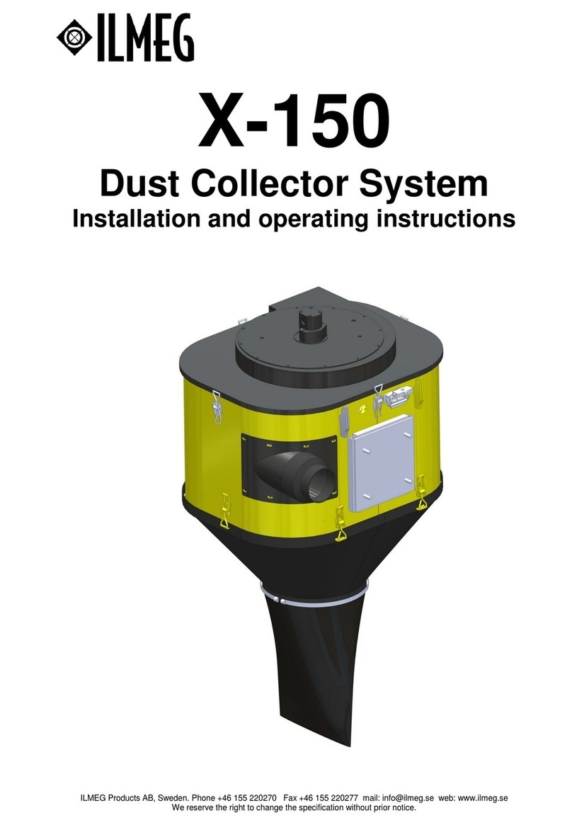
ILMEG X-125 User manual

Warning
If the air coming out of the suction fan contains dust. Stop immediately the X-125 and check for
leakages. Never operate with dust coming out of the suction fan since the suction fan will be worn out.
This can cause severe damages.
Warning
Always turn the X-125 off while moving the equipment. Quick movements of the X-125 can cause
excessive forces on the suction fan. This can cause severe damages
Warning
The X-125 contains rotating and moving parts. When servicing the X-125 make sure the hydraulic
power is switched off, the pneumatic pressure is evacuated and the electric circuit is switched off.
Caution
Components are heavy. Please use lifting devises where necessary to avoid accidents and damages.
Further safety instructions
The X-125 can only be used for what it is intended for
Only qualified and trained personnel may operate the machine
Practice how to turn off the machine in case of emergency
The maximal air pressure cannot be exceeded
Always inspect the equipment before use
Never use the equipment if you suspect it is damaged
Always use good practice and sound judgment
Be alert on what you are doing
Never use the equipment when you are tired or under the influence of drugs, alcohol or
anything else that can affect you vision, your reactions or your judgment
Participate in safety training and other trainings applicable
Never hit the equipment and never misuse it
Store the equipment in a safe place and without reach of children
Make sure that all equipment is maintained in the right way
Make sure that warning signs and decals is readable and maintained.
Make sure that unauthorized personnel never comes within the working area of the equipment
Keep the workspace free from foreign objects
Never point compressed air against yourself or anybody else. To avoid damages, never use
compressed air to clean your clothes form dust and other dirt.
Safety regulations
These instructions contain important sections dealing with safety.
Special attention must be paid to all framed safety text that begins with a warning symbol (triangle)
followed by a signal word, as shown below.
Warning denotes a hazard or hazardous procedure which CAN lead to serious or life
threatening injuries if the warning is not observed.
Caution denotes a risk or risky procedure which CAN lead to personal injury or damage
to equipment if the warning is not observed.
Also observe the following general safety rules:
Before starting the machine, read through these instructions carefully.
Also read through the safety instructions before putting the machine to use.
For reasons of product safety, the machine must not be modified.
Use approved personal protective equipment.
Use ILMEG Genuine Parts only.
Always replace worn or damaged signs.

Specification X-125 Dust Collector System
Specification:
Max hole size: 127 mm (5”)
Filter area: 8 m²
Number of filters: 2
Oil flow requirement: 22 l/min
Oil pressure requirement: 200 bar
Width x depth x height: 740 x 957 x 1062
Approx weight: 160 kg
Filter cleansing system: Reversed air through filters in sequences while drilling.
Rec. working pressure: 7 Bar (100PSI)
Installation
Mechanical installation
Make sure the mechanical bracket used for the X-125 is sufficient to carry the full weight of the dust
collector in rock drilling applications. Correct mounting is as close to the feed beam/ rock drill as
possible to reduce the suction hose length. The suction hose should be as straight as possible.

Hydraulic installation
Contact a hydraulic specialist to design the hydraulic circuit for your application.
The hydraulic hoses for the pressure and return line must have the capacity of 22 l/min and
200 Bar pressure without excessive counter pressure. Recommended size is ؽ” or Ø13
mm.
The drain line size is recommended to be Ø ¼” or Ø 6mm and connected directly to tank. No
backpressure is allowed. With too high back pressure in the drain line the hydraulic motor axle
gasket will be damaged and leakage will occur.
Warning
Always use proper quality of hydraulic hoses and fittings to reduce risk of leakage. Hydraulic pressure
can cause severe damages.
Caution
Hydraulic oil leakages have a negative effect on the environment.
Attach the pressure line to the port marked P and the return line to the port marked T.
On top of the motor the drain line should be fitted.
The maximum speed for the fan is 4000 rpm which corresponds to appr 22 l/min hydraulic flow.
Warning
Do not install more hydraulic flow than specified. Over-speed of the fan can cause severe damages.

Cleansing pulse
Suction Capacity
0
10
20
30
40
50
60
70
80
90
100
1 2 3 4 5 6
Drill rod / Depth
Suction Capacity %
i-clean,
Normal
Air pressure installation for the filter cleaning system
Connect air supply for the filter cleansing function of the dust collector. Recommended pressure is 7
BAR or 100 PSI. To safeguard full filter cleansing effect a Ø1” or Ø25 mm hose is recommended.
Warning
Always use proper quality of pneumatic hoses and fittings to reduce risk of leakage. Pneumatic
pressure can cause severe damages.
The X- 100 cleansing system
i-clean a quantum leap when it comes to suction capacity in drilling applications.
The new filter cleansing function, i-clean, ensures
high suction efficiency, even under severe drilling
conditions. The system cleans each filter
independently and continuously during the drilling
sequence. The suction capacity remains
regardless of drill rod length and rock conditions.
The need for a pre-skimmer is reduced.
During the drilling sequence the closing
valves are open, thus letting air through the
filters creating the required suction. With
certain intervals one valve closes and a short
air pulse is introduced in the closed filter
compartment to clean the filter. After the
cleansing sequence both valves are open
again until the next cleansing sequence
comes in action on the next filter.

Electrical installation
The electric control system controls the cleansing sequence and opens and closes the air valves in
the dust collector
Connect the control box to 24 V DC and connect the drilling signal to the system giving 24 V DC as
“drilling signal “ i.e. the dust collector should suction.
See separate drawings for the electrical installation.
The control system is programmable and during operations the cleaning times can be changed.
How to adjust the cleaning pulses and pauses between the pulses in the
control system:
Open the cover of the control system.
The display shows: Press “A” to set
parameters and “ESC” to go back
By pressing multiple on “A“you will toggle
between the menus.

By pressing once on “A” the menue for
setting the parameters / times during
drilling appears.
Paus means the time between the
cleaning pulse during drilling. (see i-clean
above) Factory setting is:
Pause: 1000 x 10ms = 10 seconds
Delay means tie to close one of the air
valves.
Factory setting 20 x 10 ms = 0,2 seconds
ON Means the cleaning pulses length
Factory setting 6 x 10 ms = 0,06 seconds
By pressing “A” once again you enter the
menu defining parameters when not
drilling. C1 = cleaning pulse length for
filter 1 and C2 = cleaning pulse length for
filter 2.
Factory setting for both is 1 x 100 ms =
0,1 second.
C1-C2 = time between cleaning pulses
Factory setting is 5 x 100 ms = 0,5
seconds
By Pressing “A” once again you enter the
menu number of cleaning pulses after
stop. Factory setting is 4 pulses per filter.
To change parameters
Select menu with the “A” button. Toggle up and down on the screen with “+” or “-“ and select
parameter. Press “OK” and increase or decrease parameter with the “+” or “-“ button. Press “OK”
again to confirm the new parameter.
The new parameter is now active and stored in the memory of the X-100 Control system

Suction hose installation:
The suction hose recommended for the X-125 is Ø5“or Ø125 mm. Mount the suction hose on the
machine avoiding bends on the hose to secure the best suction capacity.
LMEG Products AB, Sweden. Phone +46 155 220270 Fax +46 155 220277 mail: in[email protected] web: www.ilmeg.se
We reserve the right to change the specification without prior notice.
Table of contents
Other ILMEG Dust Collector manuals
Popular Dust Collector manuals by other brands
Grizzly
Grizzly G1030 owner's manual
Scheppach
Scheppach 5906301901 Translation of original manual
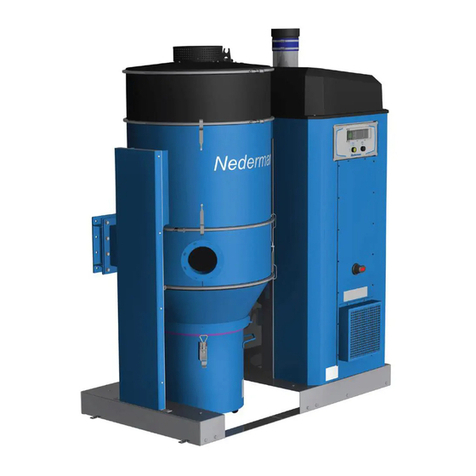
Nederman
Nederman FlexPAK 800 Installation and service manual

National Flooring Equipment
National Flooring Equipment DL6000P OPERATING & SERVICE MANUAL
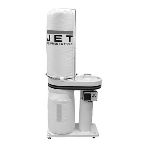
Jet
Jet DC-650A Operating instructions and parts manual

CHICO
CHICO CKU-060AT3-ACC instruction manual
Oneida Air Systems
Oneida Air Systems XSK000114 owner's manual
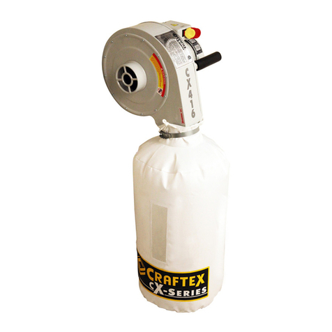
Craftex
Craftex CSX Series user manual
Quatro
Quatro Jet-Stream Operation and maintenance manual

Donaldson Torit
Donaldson Torit Downflo Oval DFO 1-1 Installation and operation manual
Axminster
Axminster T-2000CK user guide
EXAKTOR
EXAKTOR EXOA-2 manual

