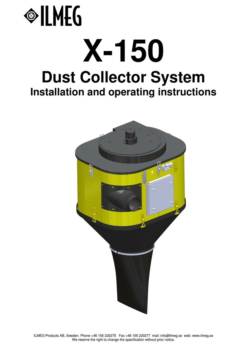
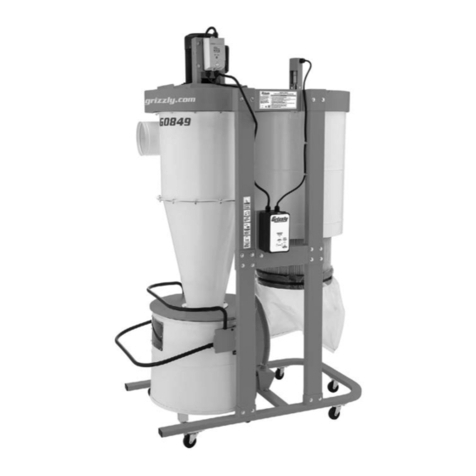
ILMEG X-150 Installation and user guide

Warning
If the air coming out of the suction fan contains dust. Stop immediately the X-150 and check for
leakages. Never operate with dust coming out of the suction fan since the suction fan will be worn out.
This can cause severe damages.
Warning
Always turn the X-150 off while moving the equipment. Quick movements of the X-150 can cause
excessiveforces on the suction fan. This can cause severe damages
Warning
The X-150 contains rotating and moving parts. When servicing the X-150 make sure the hydraulic
power is switched off, the pneumatic pressure is evacuated and the electric circuit is switched off.
Caution
Components are heavy. Please use lifting devices where necessary to avoid accidents and damages.
Further safety instructions
The X-150 can only be used for what it is intended for
Only qualified and trained personnel may operate the machine
Practice how to turn off the machine in case of emergency
The maximal air pressure cannot be exceeded
Always inspect the equipment before use
Never use the equipment if you suspect it is damaged
Always use good practice and sound judgment
Be aware of what you are doing
Never use the equipment when you are tired or under the influence of drugs, alcohol or
anything else that can affect your vision, your reactions or your judgment
Participate in safety training and other trainings applicable
Never hit the equipment and never misuse it
Store the equipment in a safe place and out of reach for children
Make sure that all equipment is maintained in the right way
Make sure that warning signs and decals are readable and maintained.
Make sure that unauthorized personnel never come within the working area of the equipment
Keep the workspace free from foreign objects
Never point compressed air towards yourself or anybody else. To avoid damages, never use
compressed air to clean your clothes from dust and other dirt.
Safety regulations
These instructions contain important sections dealing with safety.
Special attention must be paid to all framed safety text that begins with a warning symbol (triangle)
followed by a signal word, as shown below.
Warning denotes a hazard or hazardous procedure which CAN lead to serious or life
threatening injuries if the warning is not observed.
Caution denotes a risk or risky procedure which CAN lead to personal injury or damage
to equipment if the warning is not observed.
Also observe the following general safety rules:
Before starting the machine, read through these instructions carefully.
Also read through the safety instructions before putting the machine to use.
For reasons of product safety, themachine must not be modified.
Use approved personal protective equipment.
Use ILMEG Genuine Parts only.
Always replace worn or damaged signs.

Service and Maintenance Schedule
To secure maximum productivity and avoid unnecessary downtime due to breakdown and
repair activities, preventive maintenance in accordance with the schedule below is
recommended.
Service interval
Activity
Actions
During operation
Check for dust in the air from the suction fan
Stop immediately and check for
leakages
Daily
Check the seals in the pick-up hood
Change seals if necessary
Daily
Check the suction hose for leakage or damage
Change the hoseif necessary
Daily
Check for vibrations
Inspect the suction fan
Daily
Check for pneumatic leakages
Tighten leakages
Daily
Check the rubber dump valve
Change if broken
Daily
Check the hydraulic hoses and connections
Tighten or change hoses if
necessary
Yearly or after 500
hours
Change filters and wear material
Daily Maintenance
1. Start up the dust collector.
Let it run for a few minutes.
This will clean out any condensed water
from the system and rinse any leftovers
away from the filters before starting up the
next operation.
2. Check that your dust collector sucks properly 2) Checking dump valve
by looking at the rubber dump valve
(or plastic sack) which shall quickly and
strongly be sucked up against dust collector
bottom. (Only applicable where a rubber dump valve
is used.) When using a rotary valve at the bottom of
the dust collector, check the suction in the pickup
hood.
3. Check that the fan wheel is not damaged by feeling
at the filter housing for abnormal vibration.
4. Check that gasket in pickup hood (A) and 3) Feeling for vibrations
Skirt (B) are not worn out
C
5. Check that suction hose (C) is not damaged or bent A
B
4,5) Check suction hose, gasket
and skirt

6. Check that the pneumatic hoses, electrical cables and
connectors are not damaged.
7. Check that no dust is coming out through the fan
while drilling. If dust is coming through, stop the
operation immediately. A leakage in the filter house or
a filter may be damaged and need to be replaced.
Warning
Never operate with dust coming through the 7. Check if dust comes
suction fan since the suction fan will be worn out. through the suction fan
This can cause severe damages.
500 hours service or yearly service
Filter change:
8. Open the lid and secure it with the metal
holder.
9. Loosen the screws for the air inlet (I), turn the
air inlets in their bayonet holdings and fold the
whole hose kit (J) to the side:
K
10. Loosen the screws for the filter lid a few turns (K) and
turn the lid in its bayonet to unlock and J
remove the holders.
11. You can now lift up the filters easily and replace
them. While having no filter in the system check
filter cover (L), inlet/diffuser (M) and wear plate.
If worn out change!
For inlet and wear plate change see separate
instructions.
12. While changing check also sealings. If worn out,
change. I
13. Put the holders and hoses back in reverse order.
L M

Changing inlet/diffuser if worn out.
14. Remove screws (N) holding the inlet. N O
15. Take out the whole inlet/diffuser (O), (it is one unit)
16. Check the gasket, if worn out - change, otherwise
place it properly on the new inlet to prevent any
leakage.
17. Tighten the screws (N) properly on the new
inlet to prevent leakage.
Changing wear plate:
There are two ways to change wear plate, either
through the filter placement or by removing the
filter housing bottom section.
Through filter placement:
18. Remove the old wear plate (M) by loosening the
screw plate (P) inside the filter house. Make a tight
roll of the wear plate and remove it through
the hole where the filter was situated.
19. Make a tight roll of the new wear plate to
insert in the filter housing. Fit the end into
the slot (Q) and put it back under the screw
plate (P) and tighten it properly. Make sure the
rubber side faces inwards.
Through the filter housing bottom section:
20. Same as above but you need to take away
the bottom section by loosening the snap locks (R)
holding the cone (S).
21. When remounting the bottom section, make sure the sealing
is not worn out. If worn out replace. Make sure the
snap locks are properly closed to ensure the system
is air tight.

Trouble shooting
Problem
Possible Cause
Actions
Vibrations on the
dust collector
Stop and check the suction fan
Change the suction fan if
necessary
Suction capacity is
reduced
Check for leakages
Tighten or change components if
necessary
Suction capacity is
reduced
Suction hose is blocked
Clean the suction hose or change
the suction hose
Suction capacity is
reduced
Filters are due to change
Change filters
Suction capacity is
reduced
Filter cleaning function is not working
Check that the solenoid valves for
cleaning are working. Repair if
necessary
Suction capacity is
reduced
Air valves are not working
Check the air supply to the dust
collector
Suction capacity is
reduced
Air valves are not working
Check that the air valves are
opening and closing. Repair if
necessary
Suction capacity is
reduced
Suction fan is not rotating at recommended speed
Hydraulic valves are not working
Suction capacity is
reduced
Suction fan is not rotating at recommended speed
Check the hydraulic motor
Oil leakage from the
motor
Hydraulic oil drain connection blocked
Make sure the drain line has no
back pressure
Oil leakage from
the motor
Motor axle gasket is worn out
Change hydraulic motor
If your dust collector performance is inefficient though maintained daily, check the following:
Externally:
1. Check suction hose for blockage.
Clean any water or dirt from hose.
2. Check rubber dump valve (or plastic bag).
If worn or otherwise damaged change to a new
one.
3. Check that the compressor is giving OIL FREE
AIR at recommended 7 bar (100 Psi) for the filter
cleaning.
4. Check that all hose and cable connections are
fitted correctly.

Internally:
Unlock and lift up the lid. Secure the lid with the metal holder (A).
5. Check valve plate (B) for leakage.
6. Check that pneumatic cylinders (C) are working
properly.
D
7. Check that all cable connections (D) are
fitted correctly.
8. Check that all air hoses (E) and connections
are not worn out or not fitted correctly
A E C B
9. If the solenoid valve allows air to blow F
continuously, the diaphragm in the valve is
broken. G
H
If solenoid valves do not open, i.e. no air is
allowed in to the cleaning system, check hole
F) in diaphragm G). If clogged, blow clean
and refit diaphragm into the solenoid valve.
If valve still not open, change the solenoid H).

Change of the fan impeller on the X-150
Change the hydraulic motor on the X-150
Unscrew the bolts on the top of the fan. Lift
the top with a lifting devise and put it
upside-down on a working table.
Unscrew the two bolts that tighten the
conical bushing.
Insert one of the two fastening bolts in the
extra threaded hole and tighten. Now the
conical centre part is rising, thus the fan
becomes loose on the hydraulic motor axle.

The bushing must be raised minimum 5 mm
to come loose.
Lift the impeller from the motor axle.
If changing the motor:
Unbolt the hydraulic motor and replace with
a new motor.
Assembly:
To achieve the best result it is of greatest
importance that the conical bushings and
the motor axle are clean and not greased.
Therefore use appropriate solvent and
clean the parts.

Install the new impeller on the motor axle
and install the conical bushing with the
smaller diameter down in the position
where the two bolts can later be installed.
Use for instance a brass tool gently to push
the bushing down as much as possible.
Do not use excessive force.
Install the two tightening bolts and tighten
with 20 Nm torque.
NOTE: It is important to tighten the bolts
with 20 Nm torque.
Now the new impeller is installed on the
motor axle.
Check that the seal is in good condition on
top of the fan housing. If needed, replace
with cell rubber material.

Install the fan top on the fan housing and
make sure the top is centred over the nuts
in the fan housing.
Install 4 bolts and tighten them.
Lift the complete fan unit and check from
underneath that the fan is not colliding with
the suction tube in the centre. This is done
by using the hand and follow around the
tube. If the fan is colliding you need to
loosen the 4 bolts and move the top slightly
to make sure that the fan is centred.
Other manuals for X-150
1
Table of contents
Other ILMEG Dust Collector manuals
Popular Dust Collector manuals by other brands
Oneida Air Systems
Oneida Air Systems XSK000114 owner's manual
Craftsman
Craftsman 152.213361 owner's manual
Jet
Jet IAFS-1700 Operating instructions and parts manual
Grizzly
Grizzly g0703 owner's manual

Craftex
Craftex CX418 owner's manual
Donaldson Torit
Donaldson Torit Vibra-Shake VS-550 Installation and operation manual
Delta
Delta 50-760 instruction manual
Metabo
Metabo SPA 2002 operating instructions
General International
General International BT8008 Setup and operation manual
Powermatic
Powermatic PM1900TX-BK3 Instructions and parts manual
Grizzly
Grizzly Extreme Series owner's manual

Woodtec
Woodtec XW043 instruction manual


