IGM LAGUNA PFlux3 User manual

Producer / Hersteller / Výrobce / Výrobca / Gyártó / Producent:
Laguna Tools Inc
2072 Alton Pkwy
Irvine, CA 92606,
USA
Phone: +1 800-234-1976
Website: www.lagunatools.com
Distributor / Distributor / Distributor / Distribútor / Forgalmazó / Dystrybutor:
IGM nástroje a stroje s.r.o.
Ke Kopanině 560, 252 67, Tuchoměřice, Praha-západ
Česká republika
Tel: 220 950 910
www.igm.cz
SF-351AX-L 2019-30
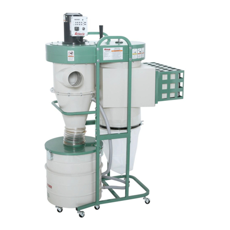
Cyclone Dust Collector
Zyklon-Absauganlage
Cyklonová odsávací jednotka
Cyklónová odsávacia jednotka
Ciklonos elszívó egység
Cyklonowe urządzenie odciągowe
PFlux 3
man_151-PFlux3_A4ob_Cyklonova odsavaci jednotka_EN+DE+CZ+SK+HU+PL_v1.7
EN Operating Instructions
(translation of the original instructions)
DE Gebrauchsanweisung
(Übersetzung der Originalgebrauch
sanweisung)
CZ Návod k obsluze
(překlad původního návodu)
SK Návod na obsluhu
(preklad pôvodného návodu)
HU Használati útmutató
(eredeti használati útmutató fordítása)
PL Instrukcja obsługi
(tłumaczenie oryginalnej instrukcji)

-2-www.igmtools.com
CE-Declaration of Conformity
Product: Cyclone Dust Collector
PFlux3
Type number: SF-351AX-L (400V)
Brand: Laguna
Manufacturer:
Laguna Tools Inc
2072 Alton Pkwy, Irvine, CA 92606, USA
Declare under our sole responsibility that this product is in conformity with the following directives:
- Machinery Directive 2006/42/ES
Designed in conformity with:
** EN ISO 12100: 2010, EN 60204-1: 2006 / AC: 2010
Technical documentation processed by:
TUV Rheinland LGA Products GMBH
Certicate no.: BM50418591 & BM50418592
2019-11 Ivo Mlej, CEO
IGM nástroje a stroje s.r.o., Ke Kopanině 560, 252 67 Tuchoměřice, Česká republika

-3-www.igmtools.com
Contents
1. Declaration of conformity
1.1 Warranty
2. PFlux3 Specications
3. General Safety Rules and Instructions
3.1 Important Safety Instructions
3.2 General Rules
3.3 Additional Safety Intructions
3.4 Power Supply
3.5 Motor Specications
3.6 Grounding Instructions
4. Parts Description
4.1 Functions
5. Assembly
6.1 Unpacking
6.2 Assembling the Unit
6. Maintenance
7. Troubleshooting
1. Declaration of conformity
We declare that this product is in compliance with the directive and the
standard mentioned on the previous page of this manual.
1.1 Warranty
IGM Tools & Machinery strives to always deliver high-quality machinery.
The warranty is governed by the valid terms and conditions of IGM Tools &
Machinery available at www.igmtools.com.
2. Specications
Motor 2200 W
Power 400V / 50Hz / 3 HP
Recommended Breaker Size 16 A, tripping characteristic C (16/3/C)
Airow (traditional method) 3831 m3/hour (2253 CFM)
Airow (realistic method) 2209 m3/hour (1299 CFM)
Max. Static Pressure 285 mm in water
Fan Diameter 390 mm
Inlet Diameter 1x 200 mm nebo 3 x 100 mm
Switch High frequency remote control switch
Noise 76 dB(A) na 3 m
Drum Collection 209 l, octagonal drum
Packing Size (ŠxDxV) 1170 x 690 x 2030 mm
Weight 160 kg
Shipping Weight 190 kg
Filter
Filtering Area: 9,5 m2
Cartridge Filter diameter 400 mm x height 900 mm
Filtration Size HEPA - 99.2 %, 0.4 Micron
Drum Collection Bag Layat Size 960 x 960 mm
3. General Safety Rules and Instructions
3.1 Important Safety Instructions
Read and understand all warnings and operating instructions before using
this equipment. Failure to follow all instructions listed below, may result in
electric shock, re, and/or serious personal injury or property damage.
Woodworking can be dangerous if safe and proper operating procedures
are not followed. As with all machinery, there are certain hazards involved
with the operation of the product. Using the machine with respect and
caution will considerably lessen the possibility of personal injury. However,
if normal safety precautions are overlooked or ignored, personal injury
to the operator may result. Safety equipment such as guards, push
sticks, hold-downs, feather boards, goggles, dust masks and hearing
protection can reduce your potential for injury. But even the best guard
won’t make up for poor judgment, carelessness or inattention. Always use
common sense and exercise caution in the workshop. If a procedure feels
dangerous, don’t try it. Figure out an alternative procedure that feels safer.
REMEMBER: Your personal safety is your responsibility.
This machine was designed for certain applications only. We strongly
recommend that this machine not be modied and/or used for any
application other than that for which it was designed. If you have any
questions relative to a particular application, do not use the machine until
you have rst contacted the manufacturer to determine if it can or should
be performed on the product.
If you have any questions relative to its application do not use the product
until you have contacted the manufacturer and we have advised you.
When using an electrical appliance, basic precautions should always be
followed, including the following:
READ ALL INSTRUCTIONS BEFORE USING (THIS APPLIANCE)
To reduce the risk of re, electric shock, or injury:
• Do not leave appliance when plugged in. Unplug from outlet when not in
use and before servicing.
• Do not use outdoors or on wet surfaces.
• Do not allow to be used as a toy. Close attention is necessary when
used by or near children.
• Use only as described in this manual. Use only manufacturer’s
recommended attachments.
• Do not use with damaged cord or plug. If appliance is not working as it
should, has been dropped, damaged, left outdoors, or dropped into water,
return it to a service centre.
• Do not pull or carry by cord, use cord as a handle, close a door on cord,
or pull cord around sharp edges or corners. Do not run appliance over
cord. Keep cord away from heated surfaces.
• Do not unplug by pulling on cord. To unplug, grasp the plug, not the cord.
• Do not handle plug or appliance with wet hands.
• Do not put any object into openings. Do not use with any opening
blocked; keep free of dust, lint, hair, and anything that may reduce air ow.
• Keep hair, loose clothing, ngers, and all parts of body away from
openings and moving parts.
• Turn off all controls before unplugging.
• Use extra care when cleaning on stairs.
EN - English
Operating Instructions (translation of the original instructions)
Dear Woodworker,
Thank you for your purchase and welcome to the Laguna Tools group of discerning woodworkers. We understand that you have a
choice of where to purchase your machines and appreciate the condence you have in the Laguna Tools brand.
Every machine manufactured by Laguna Tools has been carefully designed and well thought through from a woodworker’s perspective.
Through hands-on experience, Laguna Tools is constantly working hard to make innovative, precision products. Products that inspire
you to create works of art, are a joy to run and work on, and encourage your performance.

-4-www.igmtools.com
• Do not use to pick up ammable or combustible liquids, such as
gasoline, or use in areas where they may be present.
• Connect to a properly grounded outlet only. See Grounding Instructions
SAVE THESE INSTRUCTIONS
• Read and understand the warnings posted on the machine and in this
manual. Failure to comply with all of these warnings may cause serious
injury.
• Replace the warning labels if they become obscured or removed.
• This 3HP Portable Cyclone Dust Collector is designed and intended for
use by properly trained and experienced personnel only. If you are not
familiar with the proper and safe operation of this type of dust collector, do
not use until proper training and knowledge have been obtained.
• Do not use this machine for other than its intended use. If used for other
purposes, LAGUNA TOOLS INC., disclaims any real or implied warranty
and holds itself harmless from any injury that may result from that use.
• Always wear approved safety glasses/face shields while using this
machine.
• Before operating this dust collector, remove tie, rings, watches and other
jewelry, and roll sleeves up past the elbows. Remove all loose clothing
and conne long hair. Non-slip footwear or anti-skid oor strips are
recommended. Do not wear gloves.
• Wear ear protectors (plugs or muffs) during extended periods of
operation.
• Some dust created by power sanding, sawing, grinding, drilling and other
construction activities contain chemicals known to cause cancer, birth
defects or other reproductive harm. Some examples of these chemicals
are:
• Lead from lead based paint.
• Crystalline silica from bricks, cement and masonry products.
• Arsenic and chromium from chemically treated lumber.
Your risk of exposure varies, depending on how often you do this type
of work. To reduce your exposure to these chemicals, work in a well-
ventilated area and work with approved safety equipment, such as face or
dust masks that are specically designed to lter out microscopic particles.
• Do not operate this machine while tired or under the inuence of drugs,
alcohol or any medication.
• Make certain the switch is in the OFF position before connecting the
machine to the power source.
• Make certain the machine is properly grounded.
• Make all machine adjustments or maintenance with the machine
unplugged from the power source.
• Form a habit of checking to see that all extra equipment such as
adjusting keys, wrenches, scrap, stock, and cleaning rags are removed
away from the machine before turning on.
• Keep safety guards in place at all times when the machine is in use. If
removed for maintenance purposes, use extreme caution and replace the
guards immediately when maintenance is complete.
• Make sure the dust collector is on a at even surface and the wheels
locked in place before use.
• Check damaged parts. Before further use of the machine, a guard or
other part that is damaged should be carefully checked to determine
that it will operate properly and perform its intended function. Check for
alignment of moving parts, binding of moving parts, breakage of parts,
mounting and any other conditions that may affect its operation. A guard or
other part that is damaged should be properly repaired or replaced.
• Provide for adequate space surrounding work area and non-glare,
overhead lighting.
• Keep the oor around the machine clean and free of scrap material, oil
and grease.
• Keep visitors a safe distance from the work area. Keep children away.
• Make your workshop child proof with padlocks, master switches or by
removing starter keys.
• Give your work undivided attention. Looking around, carrying on a
conversation and “horse-play” are careless acts that can result in serious
injury.
• Maintain a balanced stance at all times so that you do not fall or lean
against the dust collector. Do not overreach or use excessive force to
perform any machine operation.
• Use the right tool at the correct speed and feed rate. Do not force a tool
or attachment to do a job for which it was not designed. The right tool will
do the job better and safer.
• Use recommended accessories; improper accessories may be
hazardous.
• Maintain machinery with care. Follow instructions for lubricating and
changing accessories.
• Turn off the machine before cleaning. Use a brush or compressed air to
remove dust or debris — do not use your hands.
• Do not stand on the machine. Serious injury could occur if the machine
tips over.
• Never leave the machine running unattended. Turn the power off and do
not leave the machine until it comes to a complete stop.
3.2 General safety rules
WARNING: FAILURE TO FOLLOW THESE RULES MAY RESULT IN
SERIOUS PERSONAL INJURY.
CHECK DAMAGED PARTS. Before further use of the unit, properly repair
or replace any part that is damaged.
FOR YOUR OWN SAFETY, READ AND UNDERSTAND THE
INSTRUCTION MANUAL BEFORE OPERATING THE MACHINE.
Learn the unit’s application and limitations as well as the specic hazards
peculiar to it.
KEEP WORK AREA CLEAN. Cluttered areas and benches invite
accidents.
DON’T USE IN DANGEROUS ENVIRONMENT. Don’t use this unit in
damp or wet locations, or expose it to rain. Keep work area well-lighted.
KEEP CHILDREN AND VISITORS AWAY. All children and visitors should
be kept a safe distance from work area.
DISCONNECT UNIT before servicing.
CHECK DAMAGED PARTS. Before further use of the unit, properly repair
or replace any part that is damaged.
FAILURE TO FOLLOW THESE RULES MAY RESULT IN SERIOUS
INJURY.
3.3 Additional Safety Instructions
Additional safety for dust collectors
Intended use. This dust collector is only intended for collecting wood dust
and chips from woodworking machines. Do not use this dust collector to
collect metal, dirt, pebbles, drywall, asbestos, lead paint, silica, liquids,
aerosols, or any ammable, combustible, or hazardous materials.
Hazardous dust. Dust created while using machinery may cause cancer,
birth defects, or long-term respiratory damage. Be aware of dust hazards
associated with each work piece material, and always wear a NIOSH-
approved respirator to reduce your risk.
Dust allergies. Dust from certain woods may cause an allergic reaction in
people and animals. Make sure you know what type of wood dust you will
be exposed to in case there is a possibility of an allergic reaction.
Wear respirator. Fine dust that is too small to be caught in the lter will
be blown into the ambient air during operation. Always wear a NIOSH-
approved respirator during operation and for a short time after to reduce
your risk of permanent respiratory damage.
Emptying dust. When emptying dust from the collection container, wear
a respirator and safety glasses. Empty dust away from ignition sources
and into an approved container.

-5-www.igmtools.com
Disconnecting power supply. Turn the switch off, disconnect the
dust collector from the power supply, and allow the impeller to come to
a complete stop before leaving the machine unattended or doing any
service, cleaning, maintenance, or adjustments.
Suspended dust particles and ignition sources. Do not operate the
dust collector in areas were explosion risks are high. Areas of high risk
include, but are not limited to, areas near pilot lights, open ames, or other
ignition sources.
Fire suppression. Only operate the dust collector in locations that contain
a re suppression system or have a re extinguisher nearby.
Impeller hazards. Do not place your hands or tools near the open inlet
during operation for any reason. The powerful suction could easily cause
accidental contact with the impeller, which will cause serious personal
injury or damage to the machine. Always keep small animals and children
away from open dust collection inlets.
Avoiding sparks. Do not allow steel or rocks to strike the impeller—this
may produce sparks. Sparks can smolder in wood dust for a long time
before a re is detected. If you accidentally cut Into wood containing tramp
metal (nails, staples, spikes, etc.), immediately turn off the dust collector,
disconnect it from power, and wait for the impeller to stop—then empty the
collection container into an approved airtight metal container.
Operating location. To reduce respiratory exposure to ne dust, locate
permanently installed dust collectors away from the working area, or in
another room that is equipped with a smoke detector. Do not operate the
dust collector in rainy or wet locations—exposure to water may create a
shock hazard or decrease the life of the machine.
Static electricity. Plastic dust lines generate high amounts of static
electricity as dust chips pass through them. Although rare, sparks caused
by static electricity can cause explosions or re. To reduce this risk, make
sure all dust lines are thoroughly grounded by using a grounding wire.
Regular cleaning. Regularly check/empty the collection bags or drum to
avoid the buildup of ne dust that can increase the risk of re. Make sure
to regularly clean the surrounding area where the machine is operated—
excessive dust buildup on overhead lights, heaters, electrical panels, or
other heat sources will increase the risk of re.
Warning: If precautions are not heeded, it may result in minor injury and/or
possible machine damage.
Warning: If precautions are not heeded, it may result in serious injury or
possibly even death.
SAVE THESE INSTRUCTIONS.
Refer to them often and use them to instruct others.
3.4 Motor Specications
Your machine is wired for 400 volts, 50 HZ alternating current. Before
connecting the machine to the power source, make sure the switch is in
the “OFF” position.
3.5 Grounding Instructions
DANGER: THIS MACHINE MUST BE GROUNDED WHILE IN USE TO
PROTECT THE OPERATOR FROM ELECTRIC SHOCK.
1. This appliance must be connected to a grounded metal, permanent
wiring system; or an equipment-grounding conductor must be run with the
circuit conductors and connected to the equipment-grounding terminal or
lead on the appliance.
The installer, such as a qualied electrician, cut (or bend over) and
insulate the grounding conductor from a eld wiring supply cable.
In the event of certain types of malfunctions or breakdowns, grounding
provides a path of least resistance for electric current—in order to reduce
the risk of electric shock.
Improper connection of the equipment-grounding wire can result in a
risk of electric shock. The wire with green insulation (with or without
yellow stripes) is the equipment-grounding wire. If repair or replacement
of the power cord or plug is necessary, do not connect the equipment-
grounding wire to a live (current carrying) terminal. Check with a qualied
electrician or service personnel if you do not understand these grounding
requirements, or if you are in doubt about whether the tool is properly
grounded. If you ever notice that a cord or plug is damaged or worn,
disconnect it from power, and immediately replace it with a new one.
Electrical Circuit Requirements
You should use a separate electrical circuit for the Laguna CFlux. The
circuit should be protected by a 16A circuit breaker with a tripping
characteristic C (16/3 / C). The power cable of the machine is factory
tted with 400V industrial plug. The machine must be connected to an
appropriate industrial socket or the machine can be connected to a
terminal board and the wiring corresponding to the recommended fuse.
ATTENTION! WIRING MAY BE CARRIED OUT BY A QUALIFIED
ELECTRICIAN ONLY.
Recommended circuit breaker: 16A (16/3/C), tripping characteristic C.
WARNING: MAKE SURE THE SOCKET IS EARTHED. IF YOU ARE
NOT SURE, HAVE THE SOCKET CHECKED BY A QUALIFIED
ELECTRICIAN.
4. Parts Description
4.1 Functional Description
High frequency remote control switch
Pic. 1
Hand held remote controller
Pic. 2
PROGRAMMING THE REMOTE CONTROL
1. Ensure the machine is ON before programming the remote control.
2. Press the BLACK set button on the bottom of the remote switch until
you hear two beeps.
3. Press the Remote set button on your hand held controller
simultaneously with the BLACK button until you hear three beeps to
complete the set up.
3HP Mobile Dust Cyclone Manual
10
IN ALL CASES, MAKE CERTAIN THE RECEPTACLE IN QUESTION IS
PROPERLY GROUNDED. IF YOU ARE NOT SURE, HAVE A QUALIFIED ELECTRICIAN CHECK
THE RECEPTACLE.
240 VOLT Single-Phase Operation
The motor supplied with your machine is a 240 volt motor. It is shipped ready-to-run
for 240volt operation.
FUNCTION
High frequency remote control switch
Hand held remote controller
ON/OFF Switch
On board circuit breaker
Octagon drum detection
HEPA Filter detection
Receiver SET button
OFF button
ON button
*Remote set button
*Used to match up a new hand held
controller with the remote switch
HEPA Filter detection
Receiver SET button
Octagon drum detection
On board circuit breaker
ON/OFF Switch
3HP Mobile Dust Cyclone Manual
10
IN ALL CASES, MAKE CERTAIN THE RECEPTACLE IN QUESTION IS
PROPERLY GROUNDED. IF YOU ARE NOT SURE, HAVE A QUALIFIED ELECTRICIAN CHECK
THE RECEPTACLE.
240 VOLT Single-Phase Operation
The motor supplied with your machine is a 240 volt motor. It is shipped ready-to-run
for 240volt operation.
FUNCTION
High frequency remote control switch
Hand held remote controller
ON/OFF Switch
On board circuit breaker
Octagon drum detection
HEPA Filter detection
Receiver SET button
OFF button
ON button
*Remote set button
*Used to match up a new hand held
controller with the remote switch
ON button OFF button
*Remote set button
*Used to match up a new hand held
controller with the remote switch

-6-www.igmtools.com
Pic. 3
5. Assembly
5.1 Unpacking
Your 3HP Mobile Dust Cyclone comes packed in a single box. Before
attempting to assemble this machine, follow these directions for
unpacking:
1. Carefully cut the banding straps and remove them from the box.
2. Cut along the tape line at the top of the box.
3. Remove all parts from the top of the styrofoam and set aside.
4. Remove the styrofoam packing material from the top of the machine.
5. Carefully take out the machine components from the box and set aside.
6. Using the diagram below, ensure that all parts are present and in good
condition.
Pic. 4
Description
A. Motor
B. Remote controller
C. Dust chute
D. Canister shield (front and back)
E. Top upright supports (3)
F. Canister cover plate
G. Base frame
H. HEPA Canister lter
I. Canister shield (side)
J. Front and back drum panel
K. Side drum panel
L. Octagon drum lid
M. Cyclone funnel
N. Cyclone barrel
O. Intake cylinder
P. Octagon drum foot peddle
Q. Canister end cap with 4” port
R. Lower upright supports (3)
S. Vacuum suction ring
T. Upright support reinforcement plate (3)
U. Foot peddle bar (left and right)
V. Foot peddle assembly ttings
V1. Lower triangular support plate (2)
V2. Foot peddle bar support (2)
V3. Lower support plate (2)
W. Inlet adapter
X. Hardware box
Y. Operating and Parts Manual
Report any missing or damaged parts to your dealer or distributor. Prior to
tool assembly and use, read this manual thoroughly to familiarize yourself
with proper assembly, maintenance and safety procedures.
5.2 General Tool Assembly
This step requires two adults. This 3HP Mobile Dust Cyclone is heavy,
be careful when lifting and handling it! Failure to comply may cause
serious injury and/or damage to the machine and/or property!
Tools Required
10 mm wrench / 12 mm wrench / 14 mm wrench
Phillips screwdriver. 4 mm hex wrench / 5 mm hex wrench
To assemble your dust cyclone, follow these steps:
For your own safety, do not connect the machine to the power source until
the machine is completely assembled. Please also make sure that you
read and understand the entire instruction manual.
ASSEMBLY TIME ESTIMATE 5-6 hours
Step 1: Turn the unit upside down. Make sure you use a cushion under
the canister top side to even out the unit to the same height as the motor.
Do not have the unit lopsided. Remove the base which has been fastened
to the (3) top upright supports.
Pic. 5
Step 2: Secure the (4) 3” wheels to the underside of the base (16)
5/16”*3/4” hex bolts and (16) 5/16”*od18*2T at washers.
Pic. 6
Step 3: Turn the base around with it standing on the (4) 4” wheels and
secure the three lower upright support panels using (6) 3/8”*3/4” hex bolts
and (6) 3/8”*OD23*2t at washers.
Each lower upright support panels numbered for its specic location.
A – shown with one dot is located on the canister side.
B – shown with two dots with extension on left is located on the front side
C – shown with two dots with extension on right is located on opposite end.
Pic. 7
Step 4: Install the foam tape to the upper and lower rims of the three
components listed, Cyclone funnel, Cyclone barrel, and Intake cylinder.
3HP Mobile Dust Cyclone Manual
13
UNPACKING
Your 3HP Mobile Dust Cyclone comes packed in a single box.Before attempting to
assemble this machine, follow these directions for unpacking:
1. Carefully cut the banding straps and remove them from the box.
2. Cut along the tape line at the top of the box.
3. Remove all parts from the top of the styrofoam and set aside.
4. Remove the styrofoam packing material from the top of the machine.
5. Carefully take out the machine components from the box and set aside.
6. Using the diagram below,ensure that all parts are present and in good condition.
DESCRIPTION (QUANTITY) Figure 1
A. Motor
B. Remote controller
C. Dust chute
D. Canister shield (front and back)
E. Top upright supports (3)
F. Canister cover plate
G. Base frame
H. HEPA Canister filter
I. Canister shield (side)
J. Front and back drum panel
K. Side drum panel
L. Octagon drum lid
M. Cyclone funnel
N. Cyclone barrel
Report any missing or damaged parts to your dealer or distributor. Prior to tool
assembly and use, read this manual thoroughly to familiarize yourself with proper
assembly, maintenance and safety procedures.
G
J
K
M
N
L
P
Q
R
T
U
V
V
V1
V2
V3
Hardware
box
Manual
O. Intake cylinder
P. Octagon drum foot peddle
Q. Canister end cap with 4”port
R. Lower upright supports (3)
S. Vacuum suction ring
T. Upright support reinforcement plate (3)
U. Foot peddle bar (left and right)
V. Foot peddle assembly fittings
V1. Lower triangular support plate (2)
V2. Foot peddle bar support (2)
V3. Lower support plate (2)
W. Inlet adapter
X. Hardware box
Y. Operating and Parts Manual
X
Y
A
B
C
D
E
F
H
I
O
W
K
S
Manuál
Nářadí
3HP Mobile Dust Cyclone Manual
11
PROGRAMMING THE REMOTE CONTROL
1. Ensure the machine is switch ON before programming the remote control.
2. Press the BLACK set button on the bottom of the remote switch until you hear two beeps.
3. Press the Remote set button on your hand held controller simultaneously with the BLACK
button until you hear three beeps to complete the set up.
Receiver set button
Receiver set button
3HP Mobile Dust Cyclone Manual
15
Step Two: Secure the (4) 3” wheels to the underside of the base (16) 5/16”*3/4”
hex bolts and (16) 5/16”*od18*2T flat washers.
Step Three:Turn the base around with it standing on the (4) 4” wheels and
secure the three lower upright support panels using (6) 3/8”*3/4”hex bolts
and (6) 3/8”*OD23*2t flat washers.
Each lower upright support panels numbered for its specific location.
A – shown with one dot is located on the canister side.
B – shown with two dots with extension on left is located on the front side
C –shown with two dots with extension on right is located on opposite end.
A
C
B
A
B
C

-7-www.igmtools.com
Pic. 8
Step 5: Attach the intake cylinder to the dust chute using (4) 5/16”*5/8” hex
spring bolts. Then, attach the cyclone barrel onto the dust chute using (12)
5/16”*3/4” hex bolts and (12) 5/16”*OD18*2t at washers followed by
attaching the cyclone funnel to the barrel using (12) 5/16”*3/4” hex bolts,
(24) 5/16”*OD18*2t at washers and (12) 5/16” hex nuts.
Pic. 9
Step 6: Take the vacuum suction tube for the cyclone barrel. This can be
located in the top Styrofoam packaging. Attach foam tape around the
inner edges of the plate facing the longer side of the tube as shown below.
Make sure to attach the foam tape on the inner edges below the bolt
holes. Attach the vacuum suction tube with the end top pointing upwards
to the dust chute using the four bolts provided.
Pic. 10
Step 7: Secure the base with (3) lower upright support panels to the
unit using (6) 5/16”*3/4” hex bolts and (6) 5/16”*OD18*2t at washers.
Pic. 11
Step 8: Secure the (3) upright support reinforcement plates using (12)
5/16”*3/4” hex bolts and (12) 5/16”*OD18*2t at washers.
Pic. 12
Step 9: With the help of another person, lift the unit up carefully to the
right side up with the motor on top and the wheels at the bottom.
Pic. 13
Step 10: Secure the side canister lter shield (I) in place using (4)
1/4”*3/4” hex bolts and (4) 1/4”*OD19*2t at washers.
Pic. 14
3HP Mobile Dust Cyclone Manual
17
Step Six: Take the vacuum suction tube for the cyclone barrel. This can be
located in the top Styrofoam packaging. Attach foam tape around the inner edges
of the plate facing the longer side of the tube as shown below. Make sure to
attach the foam tape on the inner edges below the bolt holes. Attach the vacuum
suction tube with the end top pointing upwards to the dust chute using the four
bolts provided.
Step Seven:Secure the base with (3) lower upright support panels to the
unit using (6) 5/16”*3/4”hex bolts and (6) 5/16”*OD18*2t flat washers.
Foam tape on inner side
facing longer side of tube
Vacuum tube pointing up
inside the cyclone barrel.
Foam tape on inner side
facing longer side of tube Vacuum tube pointing up
inside the cyclone barrel.

-8-www.igmtools.com
Step 11: Attach the canister lter cover plate to the dust chute using (12)
3/16”*1/2” sheet metal thread bolts.
Pic. 15
Step 12: Open the canister lter shield and secure the HEPA canister lter
onto the dust chute by fastening the band clamp on the top part of the
HEPA canister lter. Make sure the band clamp is tightly fastened. It does
not matter which side the clamp faces.
Pic. 16
Step 13: Attach the canister lter end cap to the canister lter using the (4)
latches. Cover the 4” hook up with the 100 mm (4”) rubber plug.
Pic. 17
Step 14: Secure the lower triangular support plate to the base using (4)
5/16”*3/4” hex bolts and (4) 5/16”*OD18*2t at washers. Follow the same
steps for the opposite side.
Pic. 18
Step 15: Locate the two foot pedal bars provided. There is a left side and
right side. To identify the correct side, look for the protruding nut, circled
in red below. It should be facing upwards when you place the bars on the
oor.
Pic. 19
Step 16: Slide the Foot peddle bar into the opening on the lower upright
support panel. Make sure the end of the bar is on the inside of the
triangular support plate. Follow the same steps for the opposite side.
Pic. 20
Step 17: Secure the foot peddle support to the lower upright support
panel using(4) 5/16”*1/2” carriage bolts, (4) 5/16”*OD18*2t at washers
and (4) 5/16” hex nuts. Then secure the foot peddle bar to this support
using (4) 5/16”*1-3/4” hex bolts, (8)5/16”*OD18*2t at washers and (4)
5/16” hex nuts. Follow the same steps for the opposite side.
3HP Mobile Dust Cyclone Manual
21
Step Fourteen: Secure the lower triangular support plate to the base using (4)
5/16”*3/4” hex bolts and (4) 5/16”*OD18*2t flat washers. Follow the same steps
for the opposite side.
Step Fifteen: Locate the two foot pedal bars provided. There is a left side and
right side. To identify the correct side, look for the protruding nut, circled in red
below. It should be facing upwards when you place the bars on the floor.
LEFT
RIGHT
LEFT RIGHT

-9-www.igmtools.com
Pic. 21
Step 18: Secure the base of the foot pedal bar to the triangular support
plate by holding the lower support plate vertically up against the foot pedal
bar and securing the U channel provided onto the foot pedal bar using
(2)5/16”*1-3/4” hex bolts, (4) 5/16”*OD18*2t at washers and (2) 5/16” hex
nuts from the inside out. Follow the same steps for the opposite side.
Pic. 22
Step 19: Attach the cover plate over the foot peddle assembly. Secure
using (6) 1/4”*3/4” hex bolts and (6) 1/4”*OD19*2t at washers. Follow the
same steps for the opposite side.
Pic. 23
Step 20: Attach the two ends of the Octagon foot pedal to the nut on the
foot pedal bar.
Pic. 24
Step 21: Secure the topping to the nut on the foot peddle bar. Follow
this step on the opposite side.
Pic. 25
Step 22: Secure the topping with (2) M8*30mm hex bolts.
Pic. 26
Step 23: Align the bolt hole on the movable supporting brace on the
foot peddle bar with the bolt hole on the octagon foot peddle.
3HP Mobile Dust Cyclone Manual
23
Step Eighteen: Secure the base of the foot pedal bar to the triangular support
plate by holding the lower support plate vertically up against the foot pedal bar
and securing the U channel provided onto the foot pedal bar using (2)5/16”*1-3/4”
hex bolts, (4) 5/16”*OD18*2t flat washers and (2) 5/16” hex nuts from the inside
out. Follow the same steps for the opposite side.
Step Nineteen: Attach the cover plate over the foot peddle assembly. Secure
using (6) 1/4”*3/4” hex bolts and (6) 1/4”*OD19*2t flat washers. Follow the
same steps for the opposite side.
U Channel
Hex bolt head on
inner side
U Channel
Hex bolt head
on inner side

-10-www.igmtools.com
Pic. 27
Step 24: Secure the movable supporting brace on the foot pedal bar
with the octagon foot pedal using (2) 3/8”*21mm hex bolts. Make sure the
bolt head is on the inside of the octagon foot pedal. Adjust the tightness
of this bolt accordingly. If this bolt is too tight, the Octagon foot peddle will
not work smoothly. When too loose it will not pick up the Octagon drum.
Pic. 28
Step 25: Apply foam tape to the cone ange before attaching the drum
lid. Secure the Octagon drum lid to the cyclone funnel using (8) 5/16”*3/4”
hex bolts, (16) 5/16”*OD18*2t at washers and (8) 5/16” hex nuts. Make
sure to rst attach all the bolts on before tightening the bolts. The lid will
turn when the bolts have not been tightened for alignment. Failure to
do will result in the drum lid not being able to align with the drum.
Pic. 29
Step 26: Attach the full drum detection sensor to the opening on the
drum lid located behind the cyclone funnel. When securing the sensor
make sure the end of the sensor is not longer then the drum lid rim. If it
extends longer passed the rim, the detection will not function correctly.
Pic. 30
Step 27: To adjust the distance of the sensor to detect the dust waste level
use the white plastic pin that was provided in the hardware box.
Pic. 31
Step 28: Using the white plastic pin, insert the sharp point into the top
end of the proximity sensor that is on top of the drum lid. You will nd a
small hole to on top where you can turn clockwise or anti-clockwise.
• Clockwise: Lower dust waste level in drum (Less full drum)
• Anti-clockwise: Higher dust waste level in drum (Fuller drum)
Pic. 32
Step 29: Assemble the Octagon drum. Take the (4) 3” wheels and secure
to Octagon drum base panel using (8) 3/8”*OD23*2t at washers and (4)
3/8” hex nuts. Use the at wrench provided to fasten tightly. Set this aside
to use later.
3HP Mobile Dust Cyclone Manual
27
Step Twenty Six: Attach the full drum detection sensor to the opening on the
drum lid located behind the cyclone funnel. When securing the sensor make sure
the end of the sensor is not longer then the drum lid rim. If it extends longer
passed the rim, the detection will not function correctly.
Step Twenty Seven: To adjust the distance of the sensor to detect the dust
waste level use the white plastic pin that was provided in the hardware box.
Inner view of
drum lid rim
Bottom end
of sensor
3HP Mobile Dust Cyclone Manual
26
Step Twenty Four: Secure the movable supporting brace on the foot pedal bar
with the octagon foot pedal using (2) 3/8”*21mm hex bolts. Make sure the bolt
head is on the inside of the octagon foot pedal. Adjust the tightness of this bolt
accordingly. If this bolt is too tight, the Octagon foot peddle will not work
smoothly. When too loose it will not pick up the Octagon drum.
Step Twenty Five: Apply foam tape to the cone flange before attaching the drum
lid. Secure the Octagon drum lid to the cyclone funnel using (8) 5/16”*3/4” hex
bolts, (16) 5/16”*OD18*2t flat washers and (8) 5/16” hex nuts. Make sure to first
attach all the bolts on before tightening the bolts. The lid will turn when the bolts
have not been tightened for alignment. Failure to do will result in the drum lid not
being able to align with the drum.
You will find a tag on the cone with
the following warning. Take note
and remove tag when you have
completed this step.
You will nd a tag on the
cone with the following
warning. Take note and
remove tag when you
have completed this
step.
Bottom end
of sensor
Inner view of
drum lid rim

-11-www.igmtools.com
Pic. 33
Step 30: Take the Octagon drum side panels and assemble together, secure
with (40) M4*12mm sheet metal thread bolts. Take note of the left and right
panels; do not assemble the incorrect sides. Refer to the next step.
Pic. 34
Step 31: The panels have labels R and L on them to show you which
panels should be bolted together to prevent any confusion. Please
assemble them together per photo below.
Pic. 35
Step 32: Both the left and right side lift panels have three bolt holes on
them. Take the matching side plate and secure to the outside of the panel.
(Photo shown is the inside of the panel) using (6) 1/4”*1/2” carriage bolts,
(6) 1/4”*OD19*2t at washers and (6) 1/4” hex nuts.
Step 33: Take the Octagon base panel with wheels and secure on to
the bottom of the drum using M4*12mm sheet metal thread bolts.
Pic. 37
Step 34: Take the plastic bolt end caps to cover all the bolt ends on the
inside of the Octagon drum using (40) plastic end caps. This step is
necessary to prevent any injuries caused by the sharp end of the bolts.
Pic. 38
Step 35: Once completing the assembly, apply silicone to the inside of
the drum including the base to seal and prevent air leakages.
Pic. 39
Step 36: Attach the handles to the top and bottom end on the front panel
with the window display using (4) at head Philip bolt, (4) 5/16”*OD23*2t
at washers and (4) 5/16” hex nuts.
3HP Mobile Dust Cyclone Manual
30
Step Thirty Two: Both the left and right side lift panels have three bolt holes on
them. Take the matching side plate and secure to the outside of the panel.
(Photo shown is the inside of the panel) using (6) 1/4”*1/2” carriage bolts, (6)
1/4”*OD19*2t flat washers and (6) 1/4” hex nuts.
Step Thirty Three: Take the Octagon base panel with wheels and secure on to
the bottom of the drum using M4*12mm sheet metal thread bolts
View of side panels
from inside out.
View of side panels
from inside out.
Pic. 36
3HP Mobile Dust Cyclone Manual
26
Step Twenty Four: Secure the movable supporting brace on the foot pedal bar
with the octagon foot pedal using (2) 3/8”*21mm hex bolts. Make sure the bolt
head is on the inside of the octagon foot pedal. Adjust the tightness of this bolt
accordingly. If this bolt is too tight, the Octagon foot peddle will not work
smoothly. When too loose it will not pick up the Octagon drum.
Step Twenty Five: Apply foam tape to the cone flange before attaching the drum
lid. Secure the Octagon drum lid to the cyclone funnel using (8) 5/16”*3/4” hex
bolts, (16) 5/16”*OD18*2t flat washers and (8) 5/16” hex nuts. Make sure to first
attach all the bolts on before tightening the bolts. The lid will turn when the bolts
have not been tightened for alignment. Failure to do will result in the drum lid not
being able to align with the drum.
You will find a tag on the cone with
the following warning. Take note
and remove tag when you have
completed this step.
Silicone
Caution, before tightening the
screws, make sure that the
lid is aligned with the center
of the hood.

-12-www.igmtools.com
Pic. 40
Step 37: Attach the rubber gasket to the top inner edges of the
Octagon drum. The wider end of the gasket goes up. You will need tin
snips to trim any excess rubber gasket after completing the seal.
Pic. 41
Step 38: Place the vacuum suction ring inside before inserting the
plastic bag in the Octagon drum.
Pic. 42
Step 39: Insert the plastic bag inside the Octagon drum. Open and
spread out the plastic bag to the corners and edges.
Pic. 43
Step 40: Lift the foot peddle bar. Align the Octagon drum window to the
center point of the drum lid and push the drum in. Lower the foot peddle
bar to seal the drum tight for normal machine operation.
Pic. 44
Step 41: Make sure when aligning the drum that both the left and right
side lift plates are over the topping on the foot peddle bar assembly before
lifting the foot peddle bar up. When not aligned, the drum will not be fully
sealed and will interfere with the air ow.
Pic. 45
Step 42: Remove the control panel by loosening the six bolts holding it to
the panel. Secure the two handles to the control panel using (4) M4*6mm
philip hd bolts.
3HP Mobile Dust Cyclone Manual
33
Step Thirty Eight:Place the vacuum suction ring inside before inserting the
plastic bag in the Octagon drum.
Step Thirty Nine: Insert the plastic bag inside the Octagon drum. Open and
spread out the plastic bag to the corners and edges
Vacuum suction ring
3HP Mobile Dust Cyclone Manual
34
Step Forty: Lift the foot peddle bar. Align the Octagon drum window to the center
point of the drum lid and push the drum in. Lower the foot peddle bar to seal
the drum tight for normal machine operation.
Step Forty One: Make sure when aligning the drum that both the left and right
side lift plates are over the topping on the foot peddle bar assembly before lifting
the foot peddle bar up. When not aligned, the drum will not be fully sealed and
will interfere with the air flow.
1
2
3
Vacuum suction ring
Rubber gasket

-13-www.igmtools.com
Pic. 46
Step 43: Apply foam tape to the hole on the dust chute before securing
the pressure switch using (4) M4*12MM sheet metal thread bolts.
Pic. 47
Step 44: Locate the D1-1/4”*230mm black ex hose and two D1-1/4”
hose clamps in the hardware box. Connect the one end of the ex hose
to the vacuum suction tube which is located on the top end of the cyclone
cone. Connect the other end of the ex hose to the octagon drum lid
vacuum tube which is located on the back end of the drum lid closest to
the canister lter. Secure both ends with the hose clamps provided.
Pic. 48
Step 45: If you do not want to use a plastic bag inside the octagon
collection drum, you need to block off the negative pressure. There is a
little pack containing the items needed to do this. You will also need take
the (4) 1/4”*1/2” carriage bolts, (4) 1/4”*OD19*2t at washers and (4) 1/4”
hex nuts that were securing the vacuum suction pipe to assemble the
cover plates. The vacuum suction pipe on the drum will be removed for
this. It will not have a purpose if you block off the negative pressure.
Pic. 49
Step 46: Remove the vacuum suction pipe from the drum by loosening the
(4) 1/4”*1/2” carriage bolts, (4) 1/4”*OD19*2t at washers and (4) 1/4” hex
nuts mentioned in the previous step. There will be 2 sets from the top and
2 sets from the bottom of the vacuum suction pipe.
Pic. 50
Step 47: Take the one of the cover plates, (2) 1/4”*1/2” carriage bolts,
(2) 1/4”*OD19*2t at washers and (2) 1/4” hex nuts and secure the cover
plate to the opening on the top of the drum. For the bottom holes do the
same, but rst use foam tape to cover the square opening before bolting
on the cover plate.
Pic. 51
Step 48: Remove the ex hose and clamps from the cyclone cone in
step forty one. Locate the plug provided inside the hardware box and
attach over the vacuum suction tube as shown in the picture on the right
below.
3HP Mobile Dust Cyclone Manual
36
Step Forty Four: Locate the Ø1-1/4”*230mm black flex hose and two Ø1-1/4”
hose clamps in the hardware box. Connect the one end of the flex hose to the
vacuum suction tube which is located on the top end of the cyclone cone.
Connect the other end of the flex hose to the octagon drum lid vacuum tube
which is located on the back end of the drum lid closest to the canister filter.
Secure both ends with the hose clamps provided.
Step Forty Five: If you do not want to use a plastic bag inside the octagon
collection drum, you need to block off the negative pressure. There is a little pack
containing the items needed to do this. You will also need take the (4) 1/4”*1/2”
carriage bolts, (4) 1/4”*OD19*2t flat washers and (4) 1/4”hex nuts that were
securing the vacuum suction pipe to assemble the cover plates. The vacuum
suction pipe on the drum will be removed for this. It will not have a purpose if you
block off the negative pressure.
Cyclone Cone vacuum suction tube Drum lid vacuum suction tube
Cover plates
Foam tape
Plug
Cover plates
Plug Foam tape
3HP Mobile Dust Cyclone Manual
37
Step Forty Six: Remove the vacuum suction pipe from the drum by loosening the
(4) 1/4”*1/2”carriage bolts, (4) 1/4”*OD19*2t flat washers and (4) 1/4”hex nuts
mentioned in the previous step. There will be 2 sets from the top and 2 sets from
the bottom of the vacuum suction pipe.
Step Forty Seven: Take the one of the cover plates, (2) 1/4”*1/2”carriage bolts,
(2) 1/4”*OD19*2t flat washers and (2) 1/4”hex nuts and secure the cover plate to
the opening on the top of the drum. For the bottom holes do the same, but first
use foam tape to cover the square opening before bolting on the cover plate.
Cover plates
Cover plates

-14-www.igmtools.com
Pic. 52
Step 49: Install the splitter to the inlet using (3) M4*12mm sheet metal
thread bolts. All the assembly steps have been completed.
Pic. 53
6. Maintenance procedures
CLEANING THE FILTER
To ensure proper operation of this Mobile Dust Cyclone, the HEPA canister
lter must have adequate air ow. This means the lter must be regularly
maintained by carefully blowing the lter clean using compressed air and
an air gun to release built-up particulates trapped between the lter pleats.
For heavy duty users, it is recommended to use compressed air on a
regular basis to maintain maximum ltration efciency and longer life span
of the lter.
1. Keep your cyclone switched on and operating; open both sides of the
Canister lter shield doors. Connect the D4” ex hose from the cyclone to
the D4” hook up on the canister end cap.
Pic. 54
2. While the cyclone is collecting the dust from inside the canister end cap;
use compressed air and an air gun and blow the outer surface of the
canister.
3. After cleaning the lter with the compressed air gun, follow the steps in
3HP Mobile Dust Cyclone Manual
38
Step Forty Eight: Remove the flex hose and clamps from the cyclone cone in
step forty one. Locate the plug provided inside the hardware box and attach over
the vacuum suction tube as shown in the picture on the right below.
Step Forty Nine: Install the splitter to the inlet using (3) M4*12mm sheet metal
thread bolts. All the assembly steps have been completed.
Cyclone Cone vacuum suction tube Drum lid vacuum suction tube
the next section to remove the end cap to empty out any dust left inside.
EMPTYING THE CANISTER END CAP
Periodically check the canister end cap, if it is more than one third full, it is
recommended that you empty it.
NOTE: If the canister end cap gets too full, the dust particulates may be
recirculated back into the canister lter obstructing air ow and exposing
the user to potentially harmful particulates.
1. Release the (4) latches around the canister end cap to remove.
2. Empty and re-attach using the latches.
EMPTYING THE DRUM
Periodically inspect the contents of the drum and empty as needed. To
inspect the contents of the drum:
1. Raise the drum foot peddle bar to lower the drum to the oor.
2. Roll it away from the machine, inspect and empty as needed.
ROUTINE INSPECTION
It is a good idea to routinely inspect any quality woodworking tool in order
to keep it in optimum condition. This includes inspecting all hardware for
tightness, ensuring the lter is clean, and cleaning debris and grime from
any surfaces and moving parts..
Cyclone Cone vacuum suction tube Drum lid vacuum suction tube

-15-www.igmtools.com
7. Troubleshooting guide
Machine does not start or a breaker trips.
Possible Cause
1. Power supply switched OFF or is faulty.
2. Wall fuse/circuit breaker is blown/tripped.
3. Faulty remote control.
4. Remote receiver is faulty.
5. Incorrectly wired motor connection.
6. On-board circuit breaker is tripped.
7. Wiring is open/has high resistance.
8. Faulty power switch.
9. Motor is at fault.
Possible Solution
1. Ensure power supply is ON and has the correct voltage.
2. Ensure adequate circuit size; install inlet restrictor, replace weak breaker.
3. Replace batteries; ensure unobstructed line-of-sight and signal range.
4. Inspect receiver circuit board; replace if faulty.
5. Rewire or call certied service technician or electrician.
6. Allow motor to cool, improve ventilation, press reset button.
7. Check for broken wires or poor connections, repair as necessary.
8. Replace switch.
9. Test/repair/replace.
Excessive vibration or noise during operation.
Possible Cause
1. Loose component.
2. Loose or broken motor mount.
3. Motor fan hitting fan cover.
4. Bad motor bearings.
Possible Solution
1. Inspect and tighten all bolts/nuts.
2. Tighten or replace as needed.
3. Check fan and cover; replace as needed.
4. Rotate shaft manually, check for grinding or loose shaft, replace bearings
if needed.
Loud, repetitive noise, or excessive vibration coming from
cyclone
Possible Cause
1. Machine is on uneven surface.
2. Damaged/Unbalanced impeller.
3. Loose connections.
4. Impeller is loose.
5. Motor fan hitting fan cover.
Possible Solution
1. Stabilize on a at surface.
2. Inspect impeller for dents, bends, loose ns. Replace if needed.
3. Check and re-tighten all fasteners.
4. Replace the motor and impeller.
5. Check fan and cover; replace as needed.
Dust cyclone does not adequately collect dust or chips;
poor performance.
Possible Cause
1. Canister end cap is full.
2. Filter is dirty.
3. Restricted duct line.
4. Suction route is too long or has too many sharp bends.
5. Wet lumber is clogging ducts.
6. Leaks in the duct work or too many open ports.
7. Inadequate velocity in the main suction line.
8. Wrong size ducting/ports used.
Possible Solution
1. Empty canister end cap.
2. Clean lter.
3. Clean inlet splitter.
4. Move machine closer to the point of suction, and rerun ducts to eliminate
sharp bends.
5. Use lumber with less than 20% moisture content.
6. Repair all duct leaks and close any ports not being used.
7. Increase velocity by opening 1 or 2 more blast gates to different branch
lines.
8. Re-size and re-install ducts and ttings.
Sawdust being blown into the air from the dust cyclone.
Possible Cause
1. Band clamp or end cap is not secure.
2. Loose or damaged seals.
Possible Solution
1. Re-install ensuring a tight t.
2. Replace seals and gaskets.

-16-www.igmtools.com
CE-Konformitätserklärung
Produkt: Zyklon-Absauganlage
PFlux3
Typnummer: SF-351AX-L (400V)
Marke: Laguna
Hersteller:
Laguna Tools Inc
2072 Alton Pkwy, Irvine, CA 92606, USA
Hiermit erklären wir in unserer alleinigen Verantwortung, dass dieses Produkt den folgenden Richtlinien entspricht:
- Maschinenrichtlinie 2006/42/EG
Entworfen in Übereinstimmung mit:
** EN ISO 12100: 2010, EN 60204-1: 2006 / AC: 2010
Technische Dokumentation erstellt von:
TUV Rheinland LGA Products GMBH
Číslo certikátu: BM50418591 & BM50418592
2019-11 Ivo Mlej, CEO
IGM nástroje a stroje s.r.o., Ke Kopanině 560, 252 67 Tuchoměřice, Česká republika

-17-www.igmtools.com
Inhaltsverzeichnis
1. Konformitätserklärung
1.1 Gewährleistung
2. Spezikation des Produkts
3. Allgemeine Arbeitssicherheit
3.1 Wichtige Sicherheitshinweise
3.2 Allgemeine Sicherheitsregeln
3.3 Zusätzliche Sicherheitsmaßnahmen
3.4 Motor
3.5 Anweisungen zur Erdung
4. Allgemeine Beschreibung der Maschine
4.1 Funktionen der Maschine
5. Zusammenbau der Maschine
5.1 Auspackung
5.2 Montage
6. Instandhaltung
7. Störungsbehebung
1. Konformitätserklärung
Wir erklären, dass dieses Produkt im Einklang mit der auf der vorherigen
Seite dieser Gebrauchsanweisung genannten Richtlinie und Norm.
1.1 Gewährleistung
Die IGM nástroje a stroje s.r.o. strebt danach, stets ein hochwertiges
und leistungsfähiges Produkt zu liefern. Die Inanspruchnahme der
Gewährleistung richtet sich nach den jeweils geltenden Geschäfts- und
Gewährleistungsbedingungen der IGM nástroje a stroje s.r.o.
2. Spezikation des Produkts
Motor 2200 W
Stromversorgung 400 V/50Hz / 3 Phasen
Empfohlener Schutzschalter 16 A, Abschaltcharakteristik C (16/3/C)
Luftströmung (traditionelle Messung) 3831 m3/Stunde (2253 CFM)
Luftströmung (aktuelle Messung) 2209 m3/Stunde (1299 CFM)
Max. statischer Druck 285 mm im Wasser
Lüfter-Durchmesser 390 mm
Absaugstutzen-Durchmesser 1x 200 mm oder 3 x 100 mm
Ein-/Aus-Schalter Hochfrequenz-Fernbedienung
Schalldruck 76 dB(A) auf 3 m
Abfallbehältergehalt 209 l, achtseitiger Behälter
Transportabmessung (BxLxH) 1170 x 690 x 2030 mm
Gewicht 160 kg
Transportgewicht 190 kg
Filter
Gelterter Bereich: 9,5 m2
Filterpatrone Durchmesser 400 mm x Höhe 900 mm
Filtration HEPA 99.2 % Partikeln von 0.4 Mikron
Abfallsackgröße 960 x 960 mm
3. Allgemeine Arbeitssicherheit
3.1 Wichtige Sicherheitshinweise
LESEN SIE ALLE DIE MASCHINE BETREFFENDEN HINWEISE UND
WARNUNGEN, BEVOR SIE DIE MASCHINE VERWENDEN. Die
Nichtbeachtung aller nachstehend aufgeführten Anweisungen kann zu
Stromschlägen, Brand oder schweren Personen- oder Sachschäden
führen.
Holzbearbeitung kann gefährlich sein, wenn sichere und
ordnungsgemäße Betriebsverfahren nicht befolgt werden. Wie bei allen
Maschinenanlagen gibt es beim Betrieb bestimmte Risiken. Wenn die
Maschine mit Respekt und Vorsicht verwendet wird, verringert sich die
Möglichkeit von Personenschäden erheblich. Wenn jedoch normale
Sicherheitsvorkehrungen übersehen oder ignoriert werden, kann dies zu
Verletzungen des Bedieners der Maschine führen. Sicherheitsausrüstung
wie Schutzabdeckungen, Schiebestöcke, Klemmen, Druckkämme,
Schutzbrillen, Staubmasken und Gehörschutz helfen, mögliche
Verletzungen zu vermeiden. Selbst die besten Sicherheitsmaßnahmen
können jedoch vor schlechtem Urteilsvermögen, Nachlässigkeit oder
Unaufmerksamkeit keinen Schutz bieten. Verwenden Sie in der Werkstatt
immer gesunden Menschenverstand und sein Sie vorsichtig. Wenn Sie
ein Verfahren gefährlich nden, führen Sie es nicht aus. Finden Sie ein
alternatives Verfahren, das Sie sicherer nden. BEDENKEN SIE: Ihre
persönliche Sicherheit liegt in Ihrer Verantwortung.
Die Maschine wurde ausschließlich zur bestimmungsgemäßen
Verwendung entworfen. Es wird nachdrücklich empfohlen, diese Maschine
keineswegs anzupassen oder sie zu anderen Zwecken zu verwenden,
als zu denen sie entworfen wurde. Wenn Sie Fragen zu einer bestimmten
Anwendung haben, verwenden Sie die Maschine erst, wenn Sie sich
zuerst an den Hersteller gewendet haben, um festzustellen, ob diese
Anwendung mit dem Produkt durchgeführt werden kann oder sollte.
Wenn Sie Fragen zum Gebrauch der Maschine haben, verwenden
Sie das Produkt erst, wenn Sie den Hersteller kontaktiert und von ihm
Auskünfte erhalten haben.
Bei Verwendung der Maschine sollen stets grundlegende Maßnahmen
beachtet werden, einschließlich der folgenden:
LESEN SIE ALLE ANWEISUNGEN, BEVOR SIE DIE MASCHINE
VERWENDEN Um das Brand-, Stromschlag- oder Verletzungsrisiko zu
vermeiden:
• Eingeschaltete Maschine niemals allein lassen. Wenn die Maschine
nicht verwendet wird, trennen Sie sie von der Steckdose.
• Maschine weder draußen noch auf feuchten Oberächen verwenden.
• Lassen Sie nicht zu, dass die Maschine als Spielzeug verwendet wird.
Bei Verwendung der Maschine in der Nähe von Kindern ist besonders
Vorsicht geboten.
• Maschine nur so verwenden, wie in diesem Handbuch beschrieben wird.
Ausschließlich das vom Hersteller empfohlene Zubehör verwenden.
• Wenn das Netzkabel oder der Netzstecker beschädigt sind, Maschine
nicht verwenden. Wenn die Anlage nicht so funktioniert, wie sie soll,
beschädigt ist, fallen, im Freien gelassen oder ins Wasser fallen lassen
wurde, senden Sie sie an ein Servicecenter zurück.
• Nicht am Netzkabel ziehen oder tragen, das Netzkabel nicht als Griff
verwenden, eine Tür über das Netzkabel nicht schließen und das
Netzkabel über scharfe Kanten oder Ecken nicht ziehen. Maschine auf
das Netzkabel nicht setzen. Netzkabel von heißen Oberächen fern
halten.
• Den Netzstecker aus der Steckdose nicht am Netzkabel ziehen. Fassen
Sie beim Herausziehen den Netzstecker, nicht das Netzkabel.
• Berühren Sie den Stecker oder die Anlage nicht mit nassen Händen.
• Keine Gegenstände in die Öffnungen stecken. Nicht verwenden, wenn
DE - Deutsch
Bedienungsanleitung (Übersetzung der Originalbedienungsanleitung)
Sehr geehrter Kunde,
Vielen Dank für Ihren Kauf und willkommen in der Familie der Besitzer der PFluxl Laguna Maschinen. Wir sind uns dessen bewusst,
dass Sie derzeit auf dem Markt unzählige Marken von Holzbearbeitungsmaschinen nden und wir schätzen es, dass Sie sich gerade
für die Marke Laguna Tools von IGM entschieden haben.
Jede Laguna Tools Maschine wurde sorgfältig entworfen, um den Bedürfnissen des Kunden entgegenzukommen. Dank praktischer
Erfahrung arbeitet Laguna Tools ständig daran, innovative Präzisionsprodukte zu schaffen. Produkte, die Sie zur Schaffung von
Kunstwerken inspirieren, Freude an Arbeit bieten und Ihre Leistung unterstützen.

-18-www.igmtools.com
eine beliebige Öffnung verstopft ist; frei von Staub, Schmutz, Haaren und
allem, was den Luftstrom beeinträchtigen könnte, halten.
• Haare, lose Kleidung, Finger und alle Körperteile von Öffnungen und
beweglichen Teile fern halten.
• Alle Bedienelemente ausschalten, bevor die Anlage von
Stromversorgung getrennt wird.
• Versichern Sie sich, dass die Anlage an einer stabilen Oberäche steht,
bevor Sie sie reinigen.
• Nicht in Bereichen verwenden, wo sich Brennstoffe oder brennbare
Flüssigkeiten wie etwa Benzin benden oder benden können.
• Nur an eine ordnungsgemäß geerdete Steckdose anschließen. Siehe
Anweisungen zur Erdung.
DIESE ANWEISUNGEN GUT AUFBEWAHREN
• Lesen Sie die Hinweise an der Maschine und in dieser
Bedienungsanleitung. Die Nichteinhaltung jeglicher dieser Warnungen
kann zu schweren Verletzungen führen.
• Warnschilder, die unleserlich sind oder sich ablösen, ersetzen.
• Diese tragbare Zyklon-Absauganlage ist zur professionellen Verwendung
von entsprechend geschultem und erfahrenem Personal vorgesehen.
Wenn Sie mit dem jeweiligen Betriebsverhalten der Absauganlage nicht
vertraut sind, verwenden Sie sie nicht, bevor Sie eine angemessene
Ausbildung und Kenntnisse erlangt haben.
• Die Anlage ausschließlich bestimmungsgemäß verwenden. Wenn die
Anlage anders als bestimmungsgemäß verwendet wird, schließen die IGM
nástroje a stroje s.r.o. sowie die Laguna Tools Inc. jegliche Gewährleistung
aus und halten sich von jeglicher Haftung für Verletzungen, die bei solcher
Verwendung entstehen können, frei.
• Beim Arbeiten stets angemessene Schutzbrille/Gesichtsschutz tragen.
• Vor Verwendung der Anlage, Krawatten, Ringe, Armbanduhren und
Schmuck entfernen und Ärmel über Ellbogen hochkrempeln. Vergewissern
Sie sich, dass Sie keine lose Kleidung tragen und binden Sie lange
Haare zusammen. Rutschfeste Schuhe oder Gleitschutzvorrichtungen im
Arbeitsbereich sind empfohlen. Beim Arbeiten keine Handschuhe tragen.
• Bei einer längeren Arbeit Ohrstöpsel oder Gehörschutz verwenden.
• Einige Stäube, die beim Schleifen, Sägen, Schneiden, Bohren und
anderen Tätigkeiten entstehen, enthalten Chemikalien, die Krebs und
Geburtsschäden oder andere reproduktive Schäden verursachen.
Einige Beispiele für diese Chemikalien sind:
• Blei aus bleihaltigen Farben.
• Kristalline Kieselsäure aus Ziegeln, Zement und anderen
Bauprodukten.
• Arsen und Chrom aus chemisch behandeltem Holz.
Das Risiko, dass Sie eingehen, variiert je nachdem, wie oft Sie die
jeweilige Tätigkeit durchführen. Um dieses Risiko zu eliminieren, in gut
gelüfteten Räumen arbeiten und zugelassene Sicherheitsausrüstung
verwenden, wie etwa Gesichts- oder Staubmasken, die speziell zum
Herausltern mikroskopischer Partikel entwickelt wurden.
• Verwenden Sie die Anlage nicht, wenn Sie müde sind oder unter Einuss
von Drogen, Alkohol oder anderen Medikamenten stehen.
• Vergewissern Sie sich vor dem Anschluss an Stromversorgung, dass der
Schalter aus ist (in Position OFF steht).
OFF).
• Vergewissern Sie sich, dass die Maschine ordnungsmäßig geerdet ist.
• Vergewissern Sie sich, dass die Anlage von Stromversorgung getrennt
ist, bevor Sie Einstellungen und Wartungsarbeiten vornehmen.
• Machen Sie es sich zur Gewohnheit, zu überprüfen, dass alle
zusätzlichen Geräte wie etwa Einstellschlüssel, Schraubenschlüssel,
Abfall, gebrauchtes Holz und Putzlappen entfernt sind, bevor Sie die
Anlage einschalten.
• Beim Arbeiten Schutzeinrichtungen niemals entfernen. Wenn Sie die
Schutzeinrichtungen wegen Wartung entfernen, ist äußerste Vorsicht
geboten und die Schutzeinrichtungen sind nach Beendigung der
Wartungsarbeiten sofort zurück einzubauen.
• Stellen Sie sicher, dass die Absauganlage auf einer ebenen Oberäche
steht und die Räder arretiert sind, bevor sie die Anlage verwenden.
• Maschinenteile auf Beschädigung überprüfen. Beschädigte
Schutzeinrichtungen auf richtige und ungestörte Funktionsfähigkeit
überprüfen, bevor die Anlage weiter verwendet wird. Prüfen Sie die
Ausrichtung und Befestigung beweglicher Teile sowie beschädigte
Teile der Verankerung der Anlage sowie weitere Bedingungen, die die
ordnungsmäßige Funktionsfähigkeit der Maschine beeinträchtigen
könnten. Beschädigte Schutzmittel oder Schutzeinrichtungen sind vor
jeder Verwendung der Maschine ordnungsmäßig zu reparieren oder
auszutauschen.
• Sorgen Sie für ausreichend Platz um den Arbeitsbereich und eine
blendfreie Beleuchtung des Arbeitsbereichs.
• Den Boden rund um die Maschine sauber und frei von Altmaterial und Öl
und Fett halten.
• Besucher in einem sicheren Abstand zum Arbeitsbereich halten.
Außerhalb der Reichweite von Kindern aufbewahren.
• Sichern Sie die Werkstatt vor Kindern mit Schlössern, Zentralschaltern
oder indem Sie Startschlüssel sicher lagern.
• Schenken Sie der Arbeit Ihre ungeteilte Aufmerksamkeit. Ungenügende
Aufmerksamkeit, Konversation oder „Späße“ beim Arbeiten können zu
schweren Verletzungen führen.
• Achten Sie beim Arbeiten auf eine ausgeglichene Haltung, damit Sie
nicht fallen oder sich gegen die Absauganlage lehnen. Arbeit nicht hastig
durchführen und keine übermäßige Kraft anwenden, egal für welche
Operation.
• Verwenden Sie das richtige Werkzeug mit der richtigen Geschwindigkeit
und Vorschubgeschwindigkeit. Werkzeuge oder Zubehör nicht für Arbeiten
verwenden, für die sie nicht bestimmt sind. Das richtige Werkzeug wird
die gewünschte Arbeit besser und sicherer ausführen.
• Empfohlenes Zubehör verwenden; unsachgemäßes Zubehör kann
gefährlich sein.
• Wartung der Anlage mit Sorgfalt ausführen. Anweisungen für Schmieren
und Zubehörwartung einhalten.
• Vor Reinigung Maschine ausschalten. Zur Entfernung von Sägemehl
und Abfall eine Bürste oder Druckluft verwenden - nicht mit bloßen
Händen reinigen.
• Auf die Maschine nicht treten. Umkippen der Maschine kann zu
schweren Verletzungen führen.
• Maschine niemals unbeaufsichtigt laufen lassen. Wenn die Maschine
ausgeschaltet wird, gehen Sie nicht sofort weg, sondern warten Sie bis
sie vollständig zum Stillstand gekommen ist.
3.2 Allgemeine Sicherheitsregeln
WARNUNG: DIE NICHTBEACHTUNG DIESER REGELN KANN ZU
SCHWERVERLETZUNGEN FÜHREN.
MASCHINENTEILE AUF BESCHÄDIGUNG ÜBERPRÜFEN. Die Anlage
ordnungsmäßig reparieren oder alle beschädigten Teile austauschen,
bevor sie weiter verwendet wird.
LESEN SIE DIE BEDIENUNGSANLEITUNG, BEVOR SIE DIE
MASCHINE VERWENDEN, UM EIGENE SICHERHEIT ZU
GEWÄHRLEISTEN. Machen Sie sich vertraut mit der Verwendung,
Beschränkungen und Gefahren, die sich aus der Verwendung der
Maschine ergeben können.
ARBEITSBEREICH SAUBER HALTEN. Eine unordentliche Werkstatt
oder Unordnung in der Nähe der Maschine können zu einem Unfall
führen.
NICHT IN EINER GEFÄHRLICHEN UMGEBUNG VERWENDEN. Die
Absauganlage nicht in einer feuchten oder nassen Umgebung verwenden
und sie keinem Regen aussetzen. Der Arbeitsbereich muss gut beleuchtet
sein.
KINDER UND BESUCHER DES ARBEITSBEREICHS AUSSERHALB
VON REICHWEITE DER MASCHINE HALTEN. Halten Sie alle
Kinder und unerfahrenes Personal in einem sicheren Abstand vom
Arbeitsbereich.

-19-www.igmtools.com
VOR WARTUNG MASCHINE VON STROMVERSORGUNG TRENNEN.
MASCHINENTEILE AUF BESCHÄDIGUNG ÜBERPRÜFEN. Die Anlage
ordnungsmäßig reparieren oder alle beschädigten Teile austauschen,
bevor sie weiter verwendet wird.
DIE NICHTBEACHTUNG DIESER REGELN KANN ZU
SCHWERVERLETZUNGEN FÜHREN.
3.3 Zusätzliche Sicherheitsmaßnahmen
WEITERE SICHERHEITSMASSNAHMEN FÜR DIE ABSAUGANLAGE
Bestimmungsgemäße Verwendung. Die Absauganlage ist
ausschließlich zum Sammeln von Sägemehl und Spänen von
Holzbearbeitungsmaschinen bestimmt. Verwenden Sie diese Anlage nicht,
um Metalle, Leim, Steine, Gipskarton, Asbest, Bleifarben, Kieselsäuren,
Flüssigkeiten, Aerosole oder andere brennbare, entzündliche oder
gefährliche Werkstoffe abzusaugen.
Gefährliche Stäube. Bei Verwendung der Maschinen entstandene stäube
können Krebs, Geburtsschäden oder eine langfristige Beschädigung
von Atemwegen verursachen. Seien Sie sich der mit Verwendung jedes
Werkstoffs verbundenen Staubgefahren bewusst. Tragen Sie stets ein
angemessenes Atemschutzgerät, um das Risiko zu reduzieren.
Stauballergien. Staub aus bestimmten Hölzern kann bei Menschen und
Tieren eine allergische Reaktion hervorrufen. Vergewissern Sie sich, dass
Sie wissen, welcher Art von Holzstaub Sie ausgesetzt werden, falls die
Möglichkeit einer allergischen Reaktion besteht.
Atemschutzgerät verwenden. Feinstaub, der zu klein ist, um im Filter
aufgefangen zu werden, wird während des Betriebs in die Umgebungsluft
geblasen. Tragen Sie beim Betrieb - auch für kurze Zeit - stets ein
angemessenes Atemschutzgerät, um das Risiko einer dauerhaften
Beschädigung der Atemwege zu vermeiden.
Abfallsäcke und Behälter entleeren. Tragen Sie beim Entfernen von Staub
aus dem Sammelbehälter stets ein Atemschutzgerät und eine Schutzbrille.
Staub stets fern von Zündquellen und in dafür vorgesehene Behälter
entsorgen.
Von Stromversorgung trennen. Schalter ausschalten und Absauganlage
von der Stromversorgung trennen und Motor vollständig zum Stillstand
kommen lassen, bevor Sie die Maschine unbeaufsichtigt lassen oder
jegliche Service-, Reinigungs-, Wartungs- oder Einstellungsarbeiten
durchführen.
Schwebende Staubpartikel und Zündquellen. Absauganlage nicht in
Bereichen mit hohem Explosionsrisiko betreiben. Bereiche mit hohem
Risiko umfassen, ohne darauf beschränkt zu sein, Bereiche in der Nähe
von Zündammen, offenen Flammen oder anderen Zündquellen.
Brandschutzmaßnahmen. Die Absauganlage nur an Orten
betreiben, die mit einem Feuerlöschsystem ausgestattet sind oder wo
Brandschutzmaßnahmen wie etwa Feuerlöscher verfügbar sind.
Mit Schaufellüfter verbundene Gefahren. Während des Betriebs Hände
oder Werkzeuge niemals in die Nähe der Absaugöffnung bringen - aus
welchem Grund auch immer. Das starke Saugen könnte leicht einen
versehentlichen Kontakt mit dem Schaufellüfter verursachen, was zu
schweren Verletzungen oder Beschädigung der Maschine führen kann.
Kleine Tiere und Kinder stets von der Absaugöffnung halten.
Funken vermeiden. Lassen Sie niemals zu, dass Stahl oder Steine den
Lüfter berühren - dadurch können Funken gebildet werden. Die Funken
können lange Zeit in Holzstaub schwelen, bevor ein Feuer überhaupt
erkannt wird. Wenn Sie versehentlich in Holz schneiden, das metallische
Fremdkörper enthält (Nägel, Heftklammern, usw.), die Absauganlage
sofort ausschalten, von Stromversorgung trennen und warten, bis der
Lüfter zum Stillstand gekommen ist. Anschließend den Sammelbehälter in
einen zugelassenen luftdichten Metallbehälter entleeren.
Betriebsstandort. Um das Risiko von Feinstaubaussetzung zu
reduzieren, dauerhaft aufgestellte Absauganlagen außerhalb des
Arbeitsbereichs oder in einem anderen mit Staubdetektor ausgestatteten
Raum platzieren. Die Absauganlage nicht in feuchten oder nassen
Bereichen verwenden - ein Kontakt der Maschine mit Wasser oder einer
feuchten Umgebung kann zu Stromschlägen führen oder die Lebensdauer
der Maschine beeinträchtigen.
Statische Elektrizität. Kunststoffstaubführungen erzeugen statische
Elektrizität, wenn dadurch Holzspäne geführt werden. Obwohl durch
statische Elektrizität verursachte Funken selten sind, können sie
Explosion oder Brand verursachen. Um dieses Risiko zu vermeiden,
ist dafür zu sorgen, dass alle Staubleitungen mit einem Erdungsdraht
angemessen geerdet sind.
Regelmäßige Reinigung. Sammelsäcke und Behälter regelmäßig
überprüfen/entleeren, um das Ansammeln von Feinstaub zu vermeiden
- es kann das Brandrisiko erhöhen. Arbeitsbereich, wo die Maschine
verwendet wird, regelmäßig aufräumen - übermäßige Staubansammlung
an Deckenleuchten, Heizungen, Schalttafeln oder anderen Wärmequellen
erhöht das Brandrisiko.
WARNUNG: VERNACHLÄSSIGUNG VON
VORBEUGUNGSMASSNAHMEN KANN ZU LEICHTEN
VERLETZUNGEN ODER BESCHÄDIGUNG DER MASCHINE FÜHREN.
WARNUNG: VERNACHLÄSSIGUNG VON
VORBEUGUNGSMASSNAHMEN KANN ZU SCHWERVERLETZUNGEN
ODER SOGAR ZUM TOD FÜHREN.
DIESE ANWEISUNGEN GUT AUFBEWAHREN.
Greifen Sie darauf zurück, falls erforderlich und verwenden Sie
diese, um andere Personen anzuweisen.
3.4 otor
Die Maschine ist für 16 A (16/3/C), 50 Hz Wechselstrom bestimmt.
Vergewissern Sie sich vor dem Anschluss der Maschine an
Stromversorgung, dass sich der Schalter in AUS-Position bendet.
3.5 Anweisungen zur Erdung
WARNUNG: DIE MASCHINE MUSS BEIM BETRIEB GEERDET SEIN,
DAMIT DIE BEDIENER VOR STROMSCHLÄGEN GESCHÜTZT SIND.
Diese Maschine muss dauerhaft geerdet sein. Schließen Sie die
Maschine nur an einen ordnungsgemäß geerdeten Stromkreis an.
Im Falle einer Störung oder einer Fehlfunktion bietet die Erdung einen
Weg mit dem geringsten Widerstand gegen elektrischen Strom, wodurch
das Risiko eines Stromschlags verringert wird. Die Maschine ist mit einem
Netzkabel ausgestattet, das über einen Schutzleiter und einen Stecker
mit Erdungskonnektor (Abb. 2) verfügt. Der Netzstecker darf nur an eine
geeignete und geerdete Steckdose angeschlossen werden, die allen
örtlichen Vorschriften und Verordnungen entspricht.
Ändern Sie den Netzstecker nicht, wenn er nicht in die Steckdose
passt. Wenden Sie sich an eine qualizierte Elektrofachkraft, die eine
angemessene Steckdose installieren wird. Ein unsachgemäßer Anschluss
des Erdungsleiters kann zu einem Stromschlag führen. Wenn das Kabel
oder der Netzstecker repariert werden müssen, wenden Sie sich an eine
qualizierte Elektrofachkraft.
Wenn Sie sich bezüglich der richtigen Schaltung nicht sicher sind, wenden
Sie sich an eine qualizierte Elektrofachkraft. Bei Verwendung eines
Verlängerungskabels nur ein Kabel mit drei Leitern und entsprechender
Erdung verwenden. Beschädigte oder verschlissene Kabel sind sofort
auszutauschen.
Anforderungen an Versorgungskreis
Für die Laguna PFlux Maschine sollte ein separater Stromkreis verwendet
werden. Der Stromkreis sollte mit einem 16 A Leistungsschutzschalter
Abschaltcharakteristik C (16/3/C) geschützt werden. Versorgungskabel
ist defaultmäßig mit einem 400V Industriestecker ausgestattet. Die
Maschine muss an eine entsprechende Industriesteckdose oder kann
die Maschine an eine Klemmenleiste und Leitungen entsprechend der
empfohlenen Sicherung angeschaltet werden.
ACHTUNG! DIE ANSCHALTUNG DARF NUR VON EINER
QUALIFIZIERTEN ELEKTROFACHKRAFT DURCHGEFÜHRT
WERDEN.
Empfohlener Schutzschalter: 16 A (16/3/C), Abschaltcharakteristik C.
WARNUNG: VERGEWISSERN SIE SICH, DASS DIE STECKDOSE
ORDNUNGSMÄSSIG GEERDET IST.
WENN SIE NICHT SICHER SIND, LASSEN SIE DIE STECKDOSE VON
EINER QUALIFIZIERTEN ELEKTROFACHKRAFT ÜBERPRÜFEN.

-20-www.igmtools.com
4. Allgemeine Beschreibung der Maschine
4.1 Funktionen der Maschine
Bedienpanel
Abb. 1
Fernbedienung
Abb. 2
A) Um Motorbeschädigung zu vermeiden, gibt es im Schaltschrank
eine Wärmesicherung, die den Stromkreis trenn und somit den
Motor vor Überlastung schützt. Wenn sich der Motor überhitzt oder
übermäßig Strom abnimmt. Wenn die Wärmesicherung getätigt wird,
Maschine einige Minuten abkühlen lassen. Anschließend Reset-Taste
drücken und Maschine wieder starten.
FERNBEDIENUNG EINSTELLEN
1. Versichern Sie sich, dass die Maschine eingeschaltet ist, bevor Sie die
Fernbedienung einstellen.
2. Auf der Fernbedienung schwarze Taste SET drücken, bis Sie zwei
Pieptöne hören.
3. Anschließend die Taste auf der Fernbedienung gleichzeitig mit der
schwarzen Taste drücken, bis Sie drei Pieptöne hören.
Abb. 3
5. Zusammenbau der Maschine
5.1 Auspackung
Ihre mobile Absauganlage wird in einer Kiste verpackt. Lesen Sie
bitte folgende Anweisungen zur Auspackung, bevor Sie die Maschine
zusammenbauen.
1. Bänder vorsichtig abschneiden und wegwerfen.
2. Entlang der Klebebandlinie auf der Kiste schneiden.
3. Alle Teile aus dem oberen Polystyrol-Teil entfernen und auf die Seite
legen.
4. Polystyrol-Verpackungsmaterial von dem oberen Teil der Maschine
entfernen.
5. Alle Teile aus dem oberen Polystyrol-Teil entfernen und auf die Seite
legen.
6. Nach der nachstehenden Abbildung alle Teile auf Beschädigung
überprüfen.
Abb. 4
Beschreibung
A. Motor
B. Fernbedienung
C. Staubtrichter
D. Abdeckung des Abfallbehälters (vorne und hinten)
E. Obere Stützen
F. Zyklondeckel
G. Grundrahmen
H. HEPA Filter
I. Zyklonabdeckung
G. Vorder- und Hinterabdeckung des Abfallbehälters
K. Seitenplatte des Abfallbehälters
L. Deckel des Abfallbehälters
M. Zyklonkegel
N. Zyklontrommel
O. Absaugreduktion
P. Schnellspannhebel des Abfallbehälters
Q. Sammelbehälter mit 100mm Stutzen
R. Untere Stützen (3)
S. Dichtung
T. Stützplatte (3)
U. Stäbe des Hebesystems (rechts und links)
V. Zubehör zur Montage des Hebesystems
V1. Untere Dreieck-Tragplatte (2)
V2. Stütze des Hebesystems (2)
V3. Untere Tragplatte (2)
W. Absaugreduktion
X. Werkzeuge
Y. Bedienungsanleitung
Fehlende oder beschädigte Teile Ihrem Händler oder Distributor
melden. Lesen Sie diese Gebrauchsanweisung, bevor Sie die Maschine
zusammenbauen und verwenden, um sich mit den ordnungsmäßigen
Verfahren zur Montage, Instandhaltung und Sicherheit vertraut zu
machen.
5.2 Montage
Bei diesem Schritt sind zwei erwachsene Personen erforderlich. Der
Motor des Zyklons ist schwer - beim Heben und Manipulation ist Vorsicht
geboten! Die Nichteinhaltung des ordnungsmäßigen Verfahrens kann zu
schweren Verletzungen und/oder zur Beschädigung der Maschine und/
oder Vermögenschäden führen!
Erforderliche Werkzeuge
Maulschlüssel (10 mm / 12 mm / 14mm), Kreuzschraubenzieher
Sechskantschlüssel 4mm / 5mm
Beim Zusammenbauen der Absauganlage ist wie folgt zu verfahren:
Maschine nicht an Stromquelle anschließen, solange sie nicht vollständig
zusammengebaut ist, um eigene Sicherheit zu gewährleisten. Versichern
Sie sich ferner, dass Sie die gesamte Bedienungsanleitung gelesen und
verstanden haben.
GESCHÄTZTE MONTAGEDAUER 5-6 Stunden
Schritt 1: Anlage umdrehen. Anlage so unterlegen, dass sie sich in
gleicher Höhe bendet, wie der Motor. Die Anlage sollte nicht schief
liegen. Grundrahmen der Maschine, der an (3) obere Stützen befestigt ist,
entfernen.
3HP Mobile Dust Cyclone Manual
13
UNPACKING
Your 3HP Mobile Dust Cyclone comes packed in a single box.Before attempting to
assemble this machine, follow these directions for unpacking:
1. Carefully cut the banding straps and remove them from the box.
2. Cut along the tape line at the top of the box.
3. Remove all parts from the top of the styrofoam and set aside.
4. Remove the styrofoam packing material from the top of the machine.
5. Carefully take out the machine components from the box and set aside.
6. Using the diagram below,ensure that all parts are present and in good condition.
DESCRIPTION (QUANTITY) Figure 1
A. Motor
B. Remote controller
C. Dust chute
D. Canister shield (front and back)
E. Top upright supports (3)
F. Canister cover plate
G. Base frame
H. HEPA Canister filter
I. Canister shield (side)
J. Front and back drum panel
K. Side drum panel
L. Octagon drum lid
M. Cyclone funnel
N. Cyclone barrel
Report any missing or damaged parts to your dealer or distributor. Prior to tool
assembly and use, read this manual thoroughly to familiarize yourself with proper
assembly, maintenance and safety procedures.
G
J
K
M
N
L
P
Q
R
T
U
V
V
V1
V2
V3
Hardware
box
Manual
O. Intake cylinder
P. Octagon drum foot peddle
Q. Canister end cap with 4”port
R. Lower upright supports (3)
S. Vacuum suction ring
T. Upright support reinforcement plate (3)
U. Foot peddle bar (left and right)
V. Foot peddle assembly fittings
V1. Lower triangular support plate (2)
V2. Foot peddle bar support (2)
V3. Lower support plate (2)
W. Inlet adapter
X. Hardware box
Y. Operating and Parts Manual
X
Y
A
B
C
D
E
F
H
I
O
W
K
S
Bedienungsanleitung
Werkzeuge
3HP Mobile Dust Cyclone Manual
11
PROGRAMMING THE REMOTE CONTROL
1. Ensure the machine is switch ON before programming the remote control.
2. Press the BLACK set button on the bottom of the remote switch until you hear two beeps.
3. Press the Remote set button on your hand held controller simultaneously with the BLACK
button until you hear three beeps to complete the set up.
Receiver set button
Taste zu Einstellung des
Empfängers
3HP Mobile Dust Cyclone Manual
10
IN ALL CASES, MAKE CERTAIN THE RECEPTACLE IN QUESTION IS
PROPERLY GROUNDED. IF YOU ARE NOT SURE, HAVE A QUALIFIED ELECTRICIAN CHECK
THE RECEPTACLE.
240 VOLT Single-Phase Operation
The motor supplied with your machine is a 240 volt motor. It is shipped ready-to-run
for 240volt operation.
FUNCTION
High frequency remote control switch
Hand held remote controller
ON/OFF Switch
On board circuit breaker
Octagon drum detection
HEPA Filter detection
Receiver SET button
OFF button
ON button
*Remote set button
*Used to match up a new hand held
controller with the remote switch
Indikation
Filterverstopfung
Schalter der Fernbedienung
Indikation voller
Abfallbehälter
Wärmesicherung (A)
Ein-/Aus-Schalter
3HP Mobile Dust Cyclone Manual
10
IN ALL CASES, MAKE CERTAIN THE RECEPTACLE IN QUESTION IS
PROPERLY GROUNDED. IF YOU ARE NOT SURE, HAVE A QUALIFIED ELECTRICIAN CHECK
THE RECEPTACLE.
240 VOLT Single-Phase Operation
The motor supplied with your machine is a 240 volt motor. It is shipped ready-to-run
for 240volt operation.
FUNCTION
High frequency remote control switch
Hand held remote controller
ON/OFF Switch
On board circuit breaker
Octagon drum detection
HEPA Filter detection
Receiver SET button
OFF button
ON button
*Remote set button
*Used to match up a new hand held
controller with the remote switch
EIN-Taste AUS-Taste
*Einstellung der
Fernbedienung
* Um die Fernbedienung mit dem
Fernschalter zu koppeln
This manual suits for next models
1
Table of contents
Other IGM Dust Collector manuals
Popular Dust Collector manuals by other brands

Jet EQUIPMENT & TOOLS
Jet EQUIPMENT & TOOLS DC-1900C owner's manual
Powermatic
Powermatic PM1300 Instructions and parts manual
TSI Instruments
TSI Instruments PAN231 Series Operation and service manual

Urrea
Urrea RP801 User manual and warranty
King Canada
King Canada KC-1105C instruction manual
Grizzly
Grizzly G0508 owner's manual

AQC
AQC MAXIFLO-VC owner's manual
Jet
Jet DC-500P Operating instructions and parts manual

Central Machinery
Central Machinery CENTRAL MACHINERY 98524 Set up and operating instructions

Elektra Beckum
Elektra Beckum Metabo SPA 1701 operating instructions

Numatic
Numatic HZ 190 Original instructions
Grizzly
Grizzly G4832 Installation procedures

