iLumi MESHTEK User manual

USER MANUAL
MeshTek® BLE-Ethernet-WiFi-USB Gateway
User Manual
Revision 1.2
TABLE OF CONTENTS

USER MANUAL
© ilumi Solutions, Inc. www.ilumisolutions.com Page 2 | 19
CHAPTER 1 OVERVIEW.....................................................................................................................................4
1.1 DEFINITIONS .............................................................................................................................................4
1.2 MESHTEK GATEWAY...................................................................................................................................5
CHAPTER 2 FEATURES ......................................................................................................................................6
2.1 GENERAL ..................................................................................................................................................6
2.2 WI-FI......................................................................................................................................................6
2.3 BLE.........................................................................................................................................................6
CHAPTER 3 ELECTRONIC PARAMETERS............................................................................................................7
CHAPTER 4 MESHTEK GATEWAY ARCHITECTURE ............................................................................................9
4.1 BLOCK DIAGRAM .......................................................................................................................................9
CHAPTER 5 GETTING STARTED...................................................................................................................... 10
5.1 SYSTEM REQUIREMENT ............................................................................................................................ 10
5.2 SETUP ................................................................................................................................................... 10
5.3 ADDING A GATEWAY ............................................................................................................................... 10
5.4 DELETING A GATEWAY ............................................................................................................................. 16
5.5 ADDING AND EDITING A NETWORK ............................................................................................................ 17
CHAPTER 6 REVISION HISTORY ..................................................................................................................... 19
TO OUR VALUED CUSTOMERS

USER MANUAL
© ilumi Solutions, Inc. www.ilumisolutions.com Page 3 | 19
It is our intention to provide our valued customers with the best documentation possible to ensure successful use
of your iLumi Solutions, Inc. products. To this end, we will continue to improve our publications to better suit your
needs. Our publications will be refined and enhanced as new volumes and updates are introduced.
Please note: Images used in the manual are for reference purposes only and may be different than actual product.
If you have any questions or comments regarding this publication, please contact the Marketing Communications
Department via Email at support@ilumisolutions.com. We welcome your feedback.
Errata
An errata sheet, describing minor operational differences from the data sheet and recommended workarounds,
may exist for current devices. As device/documentation issues become known to us, we will publish an errata
sheet. The errata will specify the revision of silicon and revision of the document to which it applies.
To determine if an errata sheet exists for a particular device, please check with one of the following:
•Contact MeshTek team
•Contact your local MeshTek sales representative
When contacting a sales office, please specify which device, revision of MeshTek Gateway, user manual and data
sheet (include literature number) you are using.
This document serves as the User Manual and Development Guide for the MeshTek Gateway. The document
includes specifics on the software architecture and how to use the Gateway.

USER MANUAL
© ilumi Solutions, Inc. www.ilumisolutions.com Page 4 | 19
Chapter 1 Overview
The MeshTek Gateway is a Bluetooth Low Energy (“BLE”) to Wi-Fi IoT gateway. It allows users to control and
monitor various MeshTek devices from a mobile app or cloud. The MeshTek Gateway supports both Ethernet and
Wi-Fi for connectivity to the local network and the internet.
MeshTek Gateway is required for installations / setup consisting of more than 20 MeshTek devices (end nodes)
due to limitation of Bluetooth present on iOS / Android phones.
1.1 Definitions
This section defines some terminologies used with MeshTek technology:
•MeshTek Gateway: An OpenWrt unit supporting both BLE and Wi-Fi. Referred to as “Gateway”throughout the
document
•Mesh node: A BLE peripheral that has mesh connection capability
The Bluetooth present on the MeshTek Gateway is the master which initiates a mesh network so that each mesh
node can communicate not only with its neighbors but also other mesh nodes beyond its radio range. Mesh mode
can be enabled and disabled programmatically. When mesh mode is enabled, mesh nodes can send data to each
other through BLE connections.

USER MANUAL
© ilumi Solutions, Inc. www.ilumisolutions.com Page 5 | 19
1.2 MeshTek Gateway
•Representation of end user interface and connectors available on MeshTek Gateway is shown
Connectors / Buttons
Description
USB
Micro-USB, power input (5.0VDC, 1.2A)
RJ-45
10/100Mbps Ethernet
Tactile Switch 1 (Reset)
Button to reset wireless module
Tactile Switch 2
TBD
Top LEDs present on the MeshTek Gateway indicates following status:
LEDs
Status
Blue LED blinking, 1 sec ON/OFF continuously
Ethernet is plugged in and Internet is working
Blue LED blinking, 0.5 sec ON/OFF continuously
Ethernet is not plugged in and Internet is not working
Red LED blinking, 1 sec ON/OFF continuously
Socket connection is successfully established between
Mobile App and Gateway is successfully
Red LED blinking, 0.5 sec ON/OFF continuously
Socket connection not established
Tactile
Switch 1
(Reset)
USB
RJ-45
Tactile
Switch 2
Blue
LED
Red
LED

USER MANUAL
© ilumi Solutions, Inc. www.ilumisolutions.com Page 6 | 19
Chapter 2 Features
2.1 General
•5VDC, 1.2A input via micro USB
•10/100 Ethernet
•Firmware upgrade Over-the-air (“OTA”)
•Multiple data transportation protocols
oTCP/UDP (local network)
oRemote Server / Cloud: SQS with SSL and TLS certification (when Gateway is connected to Internet)
•Operating temperature: -10°C to 50°C
2.2 Wi-Fi-Ethernet
•Wi-Fi module is based on the QCA4531 MIPS 24Kc processor operating at up to 650MHz clock rate
•Wi-Fi Standards: 802.11a/b/g, 802.11n
•MIMO Configuration: 2x2 (2-stream)
•Max output power: +20 dBm
•32 MB Flash and 64 MB DDR2 RAM
•1 x USB 2.0 host (Same port at micro USB)
•1 x Ethernet
2.3 BLE
•MeshTek-H52 Bluetooth 5.0 ready module based on Nordic’s nRF52832 (ARM® Cortex™-M4 CPU 64MHz 32-
bit processor)
•Max output power: +18.9 dBm
•Proven BLE Mesh Technology with over 30,000 MeshTek networks installed in the world
•The only BLE solution with the Auto Firmware OTA Update in a meshed network
•The only self-healing BLE mesh for high data transfer and reliable communication
•Built-in high range antenna with up to 200-meter range with reliable and secure meshing
•Can control up to 150 MeshTek devices / MeshTek enabled nodes

USER MANUAL
© ilumi Solutions, Inc. www.ilumisolutions.com Page 7 | 19
Chapter 3 Electronic Parameters
Recommended Operating Condition
Power Supply (VCC)
5VDC
Operating Temperature
-10°C to 50°C
Absolute Maximum Rating
Power Supply (VCC)
5.5VDC
Storage Temperature
-20°C to 80°C
Wi-Fi RF Performance
Wireless
IEEE 802.11b/g/n
Data Speed
•Data speed (IEEE 802.11b): 1Mbps, 2Mbps, 5.5Mbps,
11Mbps
•Data speed (IEEE 802.11g): 6Mbps, 9Mbps, 12Mbps,
18Mbps, 24Mbps, 36Mbps, 48Mbps,54Mbps
•Data speed (IEEE 802.11n): up to 150Mbps
Frequency Band
•2412MHz~2462MHz (802.11b/802.11g/802.11n(H20))
•2422MHz~2452MHz (802.11n(H40)
Channel Numbers
•11 for 802.11b/802.11g/802.11(H20)
•7 for 802.11n(H40)
Channel Separation
5MHz
Modulation Technology
•IEEE 802.11b: Direct Sequence Spread Spectrum (DSSS)
•IEEE 802.11g/802.11n: Orthogonal Frequency Division
Multiplexing(OFDM)
Transmit Power
+20dBm
Antenna
Ceramic Antenna
Antenna Gain
3dBi
Range
Up to 100 meters (open space)
Security
WPA / WPA2
Note
802.11b/g/n all support 2×2 MIMO

USER MANUAL
© ilumi Solutions, Inc. www.ilumisolutions.com Page 8 | 19
BLE RF Performance
Radio Operating Frequencies
2360MHz~2500MHz
Radio On-Air Data Rate
1Mbps
Transmit Power
+18.9dBm (RF output configured to +18.9dBm using external
PA present on the module)
Receiver Sensitivity @ BLE Mode
96 dBm (Ideal transmitter)
Antenna
Onboard PCB Antenna
Antenna Gain
0dBi
Range
Up to 200 meters (open space)
General Information
Color
White
Size
90mm x 90mm x 28mm
Weight
TBD
Accessory
•1 x 5VDC USB Adapter
•1 x Micro USB Cable (1m)
•1 x Ethernet Cable (1m)

USER MANUAL
© ilumi Solutions, Inc. www.ilumisolutions.com Page 10 | 19
Chapter 5 Getting Started
5.1 System Requirement
Following parts should be available with User for setting up the MeshTek Gateway
•WiFi Router with Ethernet port. Port forwarding on port no. 6060 should be enabled.
•MeshTek Gateway with accessory kit
•iOS device (iOS 10.0 and above)
Note: Internet connection should be available in case user wants to remotely control the MeshTek devices.
5.2 Setup
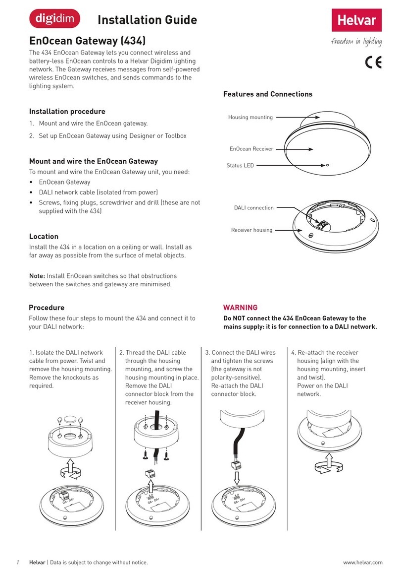
•Connect one end of the Ethernet cable to the Gateway and other end to the WiFi Router
•Enable WiFi and Bluetooth on the iOS device and connect iOS device WiFi to the WiFi Router network
•Download MeshTek app on iOS device and create an account
•Power-on the Gateway
5.3 Adding a Gateway
•User will see the Networks screen. Every Gateway needs to be added as a separate Network. Refer to Section
5.5 on how to Edit and Add a new Network
•Click on the default network “Main” to go to the Dashboard of the Network. Once in Dashboard, the app would
automatically search for the Gateway.

USER MANUAL
© ilumi Solutions, Inc. www.ilumisolutions.com Page 11 | 19
•If User has clicked on the close button then scroll to the right to “More” section and click on “Search for New
Gateway”
•After the Gateway is detected, follow the instructions available on screen. Click on “Next” and provide name
to the Gateway. Click on “Add” button present at the bottom of the screen to move onto the next setup.

USER MANUAL
© ilumi Solutions, Inc. www.ilumisolutions.com Page 12 | 19
APP would check for Local connection and Gateway Internet.
Local (socket) connection needs to be established between the Gateway and the iOS device as the configuration
i.e., User credentials and End node details needs to be synced between the two. (Note: Local connection would
be successful when both the Gateway and iOS device are present on the same local network.)

USER MANUAL
© ilumi Solutions, Inc. www.ilumisolutions.com Page 13 | 19
Internet connection on the Gateway would allow User to control the End nodes via APP remotely (via cloud).
•Gateway is ready for User. Go to the Dashboard screen to see the added Gateway. Click on “Gateway” to check
the added Gateway parameters and status of the connection.
Green dot indicates that the Gateway is online and local connections is successful.

USER MANUAL
© ilumi Solutions, Inc. www.ilumisolutions.com Page 14 | 19
It would turn to Grey when the local connections gets disconnected; it would happen when the Ethernet cable
is removed or when the iOS isn’t connected to the same network.
•As mentioned above, the APP would try to establish local connection and check for the internet before
finishing Gateway pairing process. In case both the Gateway and iOS device are not on same local network
then the APP would prompt User to “Please plug Ethernet cable and try again”. User can decide to click on
“Skip” button to finish the paring process.

USER MANUAL
© ilumi Solutions, Inc. www.ilumisolutions.com Page 15 | 19
After Ethernet cable is plugged in or both the devices are on the same network then go back to the
“Networks” page and the click on the Network in which Gateway was added. Once done, the configuration
would be synced as shown below and now the User would be able to control End nodes via Gateway

USER MANUAL
© ilumi Solutions, Inc. www.ilumisolutions.com Page 16 | 19
5.4 Deleting a Gateway
•Click on the “Gateway” present on the Dashboard and click on the “Delete Group” button present on the
bottom of the screen.
•Once deleted, the Gateway is removed from User’s Account and it becomes available for pairing again.

USER MANUAL
© ilumi Solutions, Inc. www.ilumisolutions.com Page 17 | 19
5.5 Adding and Editing a Network
For larger installations (End nodes > 20) more than one Gateway would be required. User needs to create a new
Network for each Gateway.
•Click on “Add Network” button present on the bottom right of the Networks page. Give the logical name and
description to the Network and click on “Save”.
Table of contents
Other iLumi Gateway manuals
Popular Gateway manuals by other brands
ZyXEL Communications
ZyXEL Communications AMG1312-T Series quick start guide
ACL
ACL VOLANSYS CENTAURI-200 user guide
ZyXEL Communications
ZyXEL Communications P-870HN-51B - V1.0 manual
enphase
enphase CT-100-SPLIT ROW Installation instruction
ECKELMANN
ECKELMANN Combi operating instructions
RTA
RTA 460BS-NNA4 Product user guide


