Neousys IGT-33V User manual

Neousys Technology Inc.
IGT-30 Series Industrial Gateway
User Manual
Revision 1.2

Table of Contents
Table of Contents
Table of Contents...................................................................................................................2
Legal Information...................................................................................................................4
Contact Information...............................................................................................................5
Declaration of Conformity.....................................................................................................5
Copyright Notice....................................................................................................................6
Safety Precautions.................................................................................................................7
Service and Maintenance ......................................................................................................8
ESD Precautions....................................................................................................................8
About This Manual.................................................................................................................9
1. Introduction
1.1 IGT-30 Series Overview............................................................................................10
1.2 IGT-30 Series Hardware Specifications..................................................................11
2. System Overview
2.1 IGT-30 Series Packing List.......................................................................................12
2.2 Enclosure Dimensions.............................................................................................13
2.3 IGT-30D/ IGT-31D Front Panel..................................................................................14
2.4 IGT-33V/ IGT-34C Front Panel..................................................................................15
2.5 IGT-30D/ IGT-31D Top Panel.....................................................................................16
2.6 IGT-33V/ IGT-34C Top Panel.....................................................................................17
3. System LED
3.1 Power & System Status LED ...................................................................................18
3.2 Ethernet Port & LED.................................................................................................19
4. Digital I/O and DC Connector
4.1 Digital Input Connector (X1) & Pin Definition.........................................................20
4.2 Digital Output Connector (X2) & Pin Definition......................................................22
4.3 Serial Port (X3) & Console Port Pin Definition.......................................................23
4.4 DC Connector Definition..........................................................................................24
5. System Setup
5.1 External microSDHC Installation/ Replacement ....................................................26
5.2 Internal microSDHC Card & Battery Installation....................................................27
5.3 mini PCIe Installation ...............................................................................................33
5.4 DIN Rail Installation..................................................................................................41
5.5 Powering-on the System..........................................................................................43
5.5.1 DC Input............................................................................................................43
5.5.2 Power Device Mode..........................................................................................44
6. Initial Login
6.1 Login via Console Port ............................................................................................45
6.2 Login via Ethernet....................................................................................................48
6.3 Utility Script ..............................................................................................................52
7. Digital Input and Output

3
7.1 IGT-30D/31D..............................................................................................................53
7.1.1 Mode of Digital Inputs .......................................................................................53
7.1.2 Wiring of Digital Input........................................................................................54
7.1.3 Wiring of Digital Output.....................................................................................55
7.2 IGT-33C/ 34C.............................................................................................................56
7.2.1 Wiring of Digital Input........................................................................................56
7.2.2 Wiring of Digital Output.....................................................................................56
8. Analog Input
8.1 IGT-33V......................................................................................................................57
8.1.1 Voltage Input.....................................................................................................57
8.1.2 Wiring of Voltage Input......................................................................................57
8.2 IGT-34C......................................................................................................................58
8.2.1 Mode of Current Input.......................................................................................58
8.2.2 Wiring of Current Input......................................................................................58
Appendix A Sysfs Mapping
IGT-30D .................................................................................................................................59
IGT-31D .................................................................................................................................60
IGT-33V..................................................................................................................................61
IGT-34C .................................................................................................................................62
Appendix B Utility Script
Button State Monitor..............................................................................................................63
Analog Input monitor..............................................................................................................64
Digital Input Monitor...............................................................................................................65
User Definable LED ...............................................................................................................65
Digital Output Control/ Monitor...............................................................................................66
RS-232/ 422/ 485 Switch .......................................................................................................67
Appendix C Analog Function

Legal Information
Legal Information
All Neousys Technology Inc. products shall be subject to the latest Standard
Warranty Policy
Neousys Technology Inc. may modify, update or upgrade the software, firmware or
any accompanying user documentation without any prior notice. Neousys
Technology Inc. will provide access to these new software, firmware or
documentation releases from download sections of our website or through our
service partners.
Before installing any software, applications or components provided by a third party,
customer should ensure that they are compatible and interoperable with Neousys
Technology Inc. product by checking in advance with Neousys Technology Inc..
Customer is solely responsible for ensuring the compatibility and interoperability of
the third party’s products. Customer is further solely responsible for ensuring its
systems, software, and data are adequately backed up as a precaution against
possible failures, alternation, or loss.
For questions in regards to hardware/ software compatibility, customers should
contact Neousys Technology Inc. sales representative or technical support.
To the extent permitted by applicable laws, Neousys Technology Inc. shall NOT be
responsible for any interoperability or compatibility issues that may arise when (1)
products, software, or options not certified and supported; (2) configurations not
certified and supported are used; (3) parts intended for one system is installed in
another system of different make or model.

Contact Information / Declaration of Conformity
Contact Information
Headquarters
(Taipei, Taiwan)
Neousys Technology Inc.
15F, No.868-3, Zhongzheng Rd., Zhonghe Dist., New Taipei City, 23586, Taiwan
Tel: +886-2-2223-6182 Fax: +886-2-2223-6183 Email, Website
Americas
(Illinois, USA)
Neousys Technology America Inc.
3384 CommercialAvenue, Northbrook, IL 60062, USA
Tel: +1-847-656-3298 Email, Website
China Neousys Technology (China) Ltd.
Room 612, Building 32, Guiping Road 680, Shanghai
Tel: +86-2161155366 Email, Website
Declaration of Conformity
FCC This equipment has been tested and found to comply with the limits for a Class
Adigital device, pursuant to part 15 of the FCC Rules. These limits are designed
to provide reasonable protection against harmful interference when the
equipment is operated in a commercial environment. This equipment generates,
uses, and can radiate radio frequency energy and, if not installed and used in
accordance with the instruction manual, may cause harmful interference to
radio communications. Operation of this equipment in a residential area is likely
to cause harmful interference in which case the user will be required to correct
the interference at own expense.
CE The product(s) described in this manual complies with all applicable European
Union (CE) directives if it has a CE marking. For computer systems to remain
CE compliant, only CE-complia
nt parts may be used. Maintaining CE
compliance also requires proper cable and cabling techniques.

Copyright Notice
Copyright Notice
All rights reserved. This publication may not be reproduced, transmitted,
transcribed, stored in a retrieval system, or translated into any language or
computer language, in any form or by any means, electronic, mechanical,
magnetic, optical, chemical, manual or otherwise, without the prior written
consent of Neousys Technology, Inc.
Disclaimer This manual is intended to be used as an informative guide only and is subject
to change without prior notice. It does not represent commitment from Neousys
Technology Inc. Neousys Technology Inc. shall not be liable for any direct,
indirect, special, incidental, or consequential damages arising from the use of
the product or documentation, nor for any infringement on third party rights.
Patents and
Trademarks
Neousys, the Neousys logo, Expansion Cassette, MezIOTM are registered
patents and trademarks of Neousys Technology, Inc.
Windows is a registered trademark of Microsoft Corporation.
Intel®, Core™ is a registered trademark of Intel Corporation
NVIDIA®, GeForce®is a registered trademark of NVIDIA Corporation
Texas Instruments (TI) and Sitara are registered trademarks of Texas
Instruments Incorporated.
All other names, brands, products or services are trademarks or registered
trademarks of their respective owners.

Safety Precautions
Safety Precautions
Read these instructions carefully before you install, operate, or transport the system.
Install the system or DIN rail associated with, at a sturdy location
Install the power socket outlet near the system where it is easily accessible
Secure each system module(s) using its retaining screws
Place power cords and other connection cables away from foot traffic. Do not
place items over power cords and make sure they do not rest against data cables
Shutdown, disconnect all cables from the system and ground yourself before
touching internal modules
Ensure that the correct power range is being used before powering the device
Should a module fail, arrange for a replacement as soon as possible to minimize
down-time
If the system is not going to be used for a long time, disconnect it from mains
(power socket) to avoid transient over-voltage

Service and Maintenance/ ESD Precautions
Service and Maintenance
ONLY qualified personnel should service the system
Shutdown the system, disconnect the power cord and all other connections
before servicing the system
When replacing/ installing additional components (expansion card, memory
module, etc.), insert them as gently as possible while assuring proper connector
engagement
ESD Precautions
Handle add-on module, motherboard by their retention screws or the module’s
frame/ heat sink. Avoid touching the PCB circuit board or add-on module
connector pins
Use a grounded wrist strap and an anti-static work pad to discharge static
electricity when installing or maintaining the system
Avoid dust, debris, carpets, plastic, vinyl and styrofoam in your work area.
Do not remove any module or component from its anti-static bag before
installation

About This Manual
9
About This Manual
This manual introduces Neousys IGT-30 series, an industrial grade gateway that can
be deployed in a complex communication network. The manual covers IGT-30 series
connections, LED indicators, initial setup and installation of the system.
Revision History
Version Date Description
1.0 Sep. 2019 Initial release
1.1 Aug. 2020 Added IGT-33V/ IGT-34C
1.2 Sep. 2021
Updated:
IGT-33V analog voltage input wiring
IGT34C current input wiring
IGT-30 Series
10
1. Introduction
Neousys IGT-30 series are rugged industrial grade ARM-based gateway. Based on
Texas Instruments’ Sitara AM335x family and coupled with Debian operating system,
IGT-30 series are in compliance with CE/FCC, shock, vibration, etc. certifications.
IGT-30 Series Overview
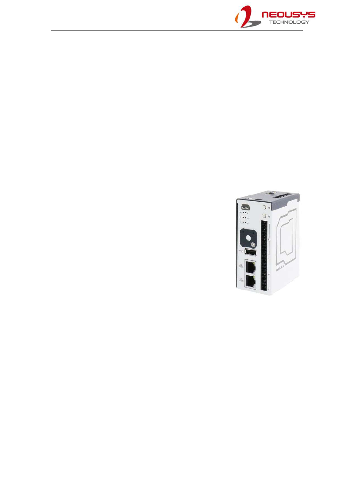
Neousys IGT-30 series, equipped with AM3352 from Texas Instrument's Sitara AM335x
family, is an ARM-based Box PC aimed at Industrial Internet of Things (IIoT) Gateway
and Industry 4.0 applications. As required by any industrial applications, IGT-30 series is
shipped as a ready system preinstalled with Debian and in compliance with common
industrial certifications such as CE/FCC, shock and vibration. It has a power input range
of 12 to 25 VDC and a wide operating temperature from
-25°C to 70°C to ensure IGT-30 continues to function under
harsh industrial conditions.
IGT-30 series supports PoE Powered Device (PD) mode
meaning it can be powered by a LAN cable from a PoE
Power Sourcing Equipment (PSE), and at the same time
transfer data via this cable as well. IGT-30 series has I/Os
that are applicable to a range of industrial grade sensors. It
features one USB2.0 port, two 10/100M LAN ports, one
configurable COM port (RS-232/422/485), one RS-485
(IGT-33V/ 34C only) and a CAN bus port (IGT-31D only). In
addition to the ports mentioned, there are built-in isolated digital input channels that
accept discrete signals from various sensors or buttons/ switches. There are also built-in
isolated digital output channels to control actuators and indicators.
Communication wise, IGT-30 series has a mini PCIe slot and a USIM holder allowing it to
transmit acquired data and system status via 3G, 4G or WiFi (mini PCIe WiFi module).
There are two openings on top of IGT-30 series for users to mount the SMA connector of
the wireless module. In terms of storage, IGT-30 series has dual microSDHC slots, one
internal and one external. This design allows users to separate system/ user data and
can also expedite in OS deployment for mass production. Inherited from its predecessor,
IGT-30 series features six LED indicators and two function buttons that can be
programmed by users. The function buttons can act as controls for IGT-30 series and
exclude the need for external input devices, such as keyboard/ mouse.
IGT-30 Series
11
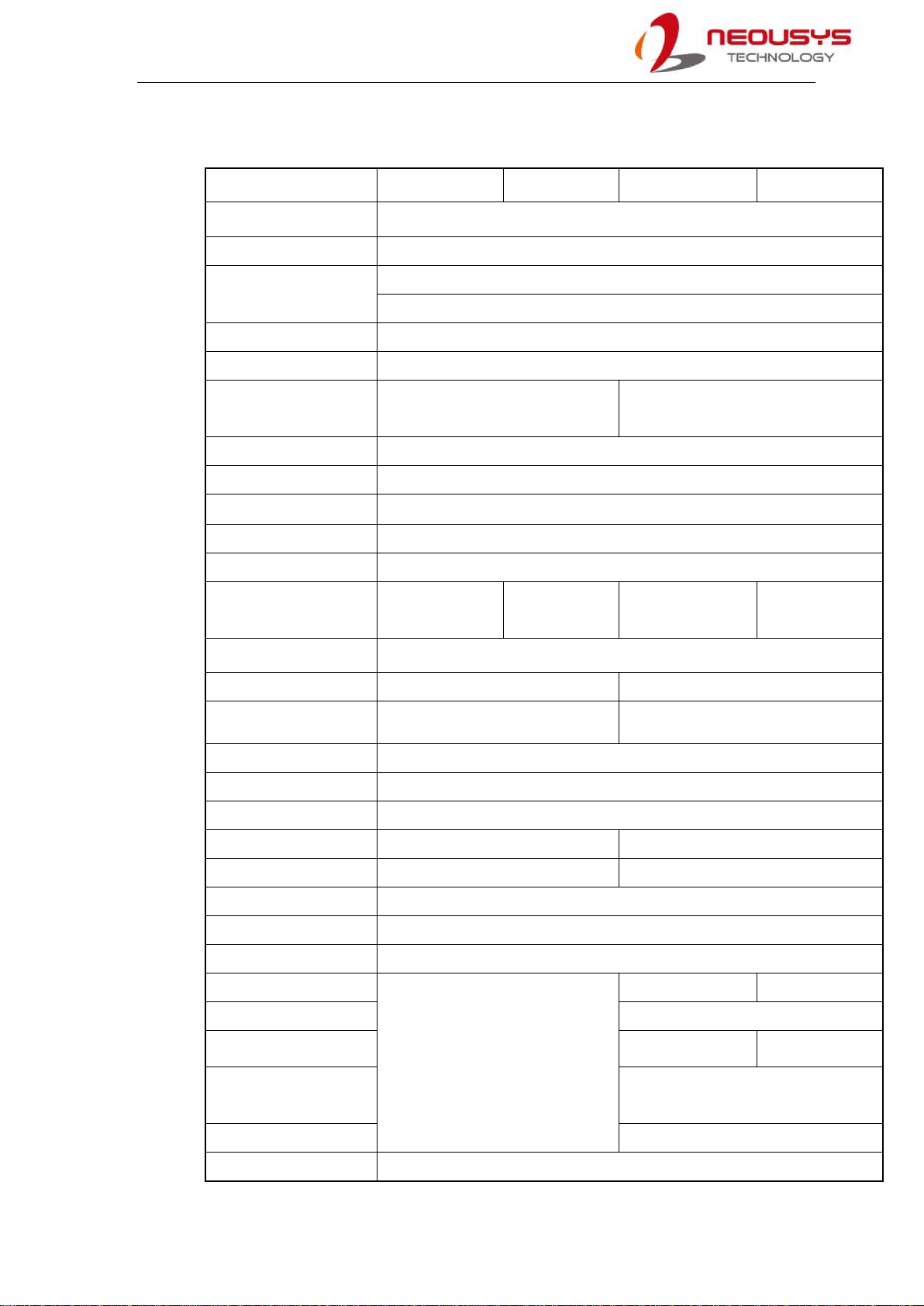
1.1 IGT-30 Series Specifications
IGT-30D IGT-31D IGT-33V IGT-34C
Processor Texas Instrument Sitara AM3352 1GHz Processor
Memory module 1GB DDR3L SDRAM
Ethernet: 1x 10/ 100Mbit LAN
1x 10/ 100Mbit LAN with PoE (PD)
USB port 1x USB2.0
Storage expansion 2x microSDHC (internal x1, external x1)
Serial port 1x software configurable RS-232/ 422/ 485
port
1x software configurable RS-232/ 422/ 485 port
1x RS-485 port
Console port 1x 3-wired RS-232 port
User LED 6x user programmable LED
Function button 2x user programmable function buttons
Power button 1x power button
Reset button 1x reset button
CAN bus NA Isolated CAN bus
2.0 A/ B NA NA
Wireless expansion mini PCIe (USB signal only) + internal SIM slot x1
Digital input 8x digital input channels 2x digital input channels
Input signal type Dry contact/ sinking/ sourcing Dry contact/ sinking
Isolation voltage 3750Vms
Logic “0” voltage 11~24V
Logic “1” voltage 0~1.5V
Digital output 2x output channels 6x output channels
Output signal type Sinking/ sourcing Sinking
Isolation voltage 1500Vms
Rated driving current 500mA
Rated driving voltage 24 VDC/ VAC
Analog Input
N/A
8-ch 4-ch
Resolution 16 bit
Input Range 0-10V/ -5~5V/ -10~10V 4-20mA/ 0-20mA
Accuracy ±0.1%, FSR @ 25°C
±0.3%, FSR @ 0°C, 60°C
Response Frequency 100Hz (10ms) all channels
DC Input Range 12 ~ 25 VDC

IGT-30 Series
12
2. System Overview
Upon receiving and unpacking your IGT-30 series system, please check immediately if
the package contains all the items listed in the following table. If any item(s) are missing
or damaged, please contact your local dealer or Neousys Technology.
2.1 IGT-30 Series Packing List
System
Item IGT-30 series Qty
1 IGT-30 series 1
2 3-pole terminal block 1
3 10-pole terminal block 3
4 Cover plate 1
5 M3 flat screw 1
6 DIN-rail clip set 1
NOTE
The BR2032 battery is not included with the purchase of the system. The battery is user
provided and is responsible for the system’s real-time clock.
IGT-30 Series
13
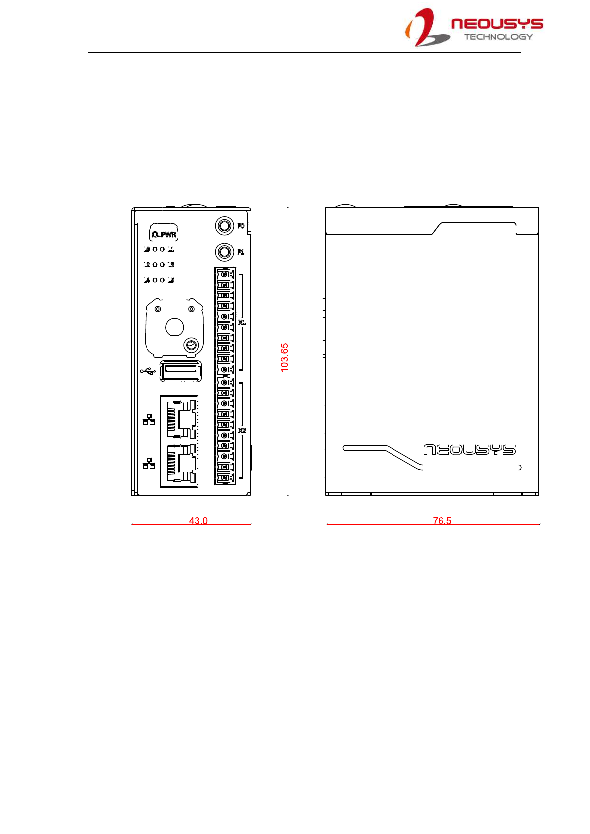
2.2 Enclosure Dimensions
Neousys IGT-30 series enclosure dimensions come in a footprint measuring just 103.65
(H) x 43.0 (W) x 76.5 (D) mm. The compact dimensions make it easy to setup and deploy
in areas where space is limited. It also comes with a DIN clip for DIN-rail mounting
purposes.

IGT-30 Series
14
2.3 IGT-30D/ IGT-31D Front Panel
There is a power status indicator LED, six user-definable LEDs, microSDHC expansion
slot (under cover plate), SIM card slot, USB port, Ethernet port, two user-definable
function buttons, console port, DI/ DO connectors, CAN bus (IGT-31D) and reserved
ports.

IGT-30 Series
15
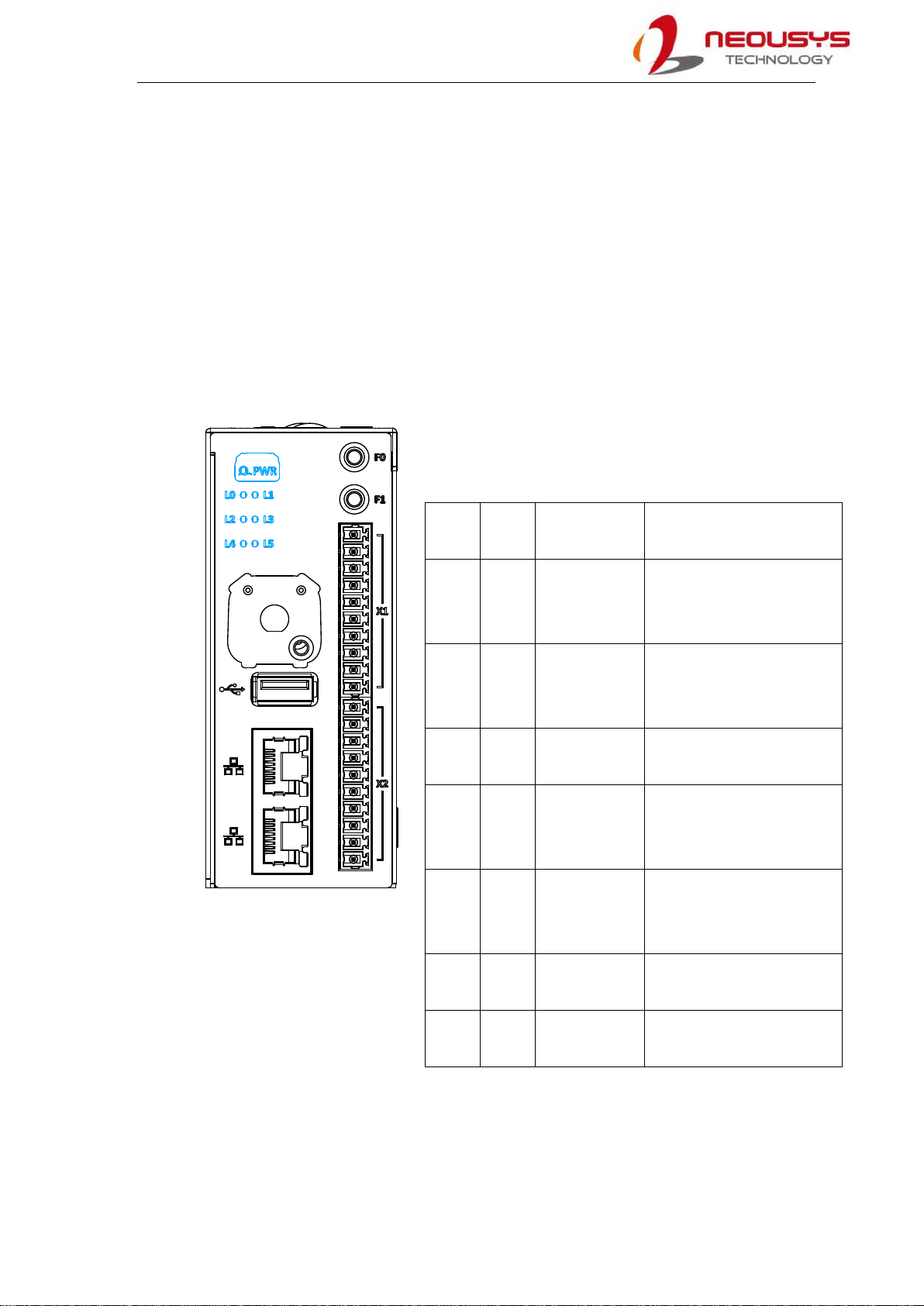
2.4 IGT-33V/ IGT-34C Front Panel
There is a power status indicator LED, six user-definable LEDs, microSDHC expansion
slot (under cover plate), SIM card slot, USB port, Ethernet port, two user-definable
function buttons, console port, DI/ DO connectors and analog input (AI) connectors.
IGT-30 Series
16
2.5 IGT-30D/ IGT-31D Top Panel
Top of the enclosure features a 3-pin DC power connector, 1x RS-232/ 422/ 485, console
port, power button, reset button and an antenna opening.

IGT-30 Series
17
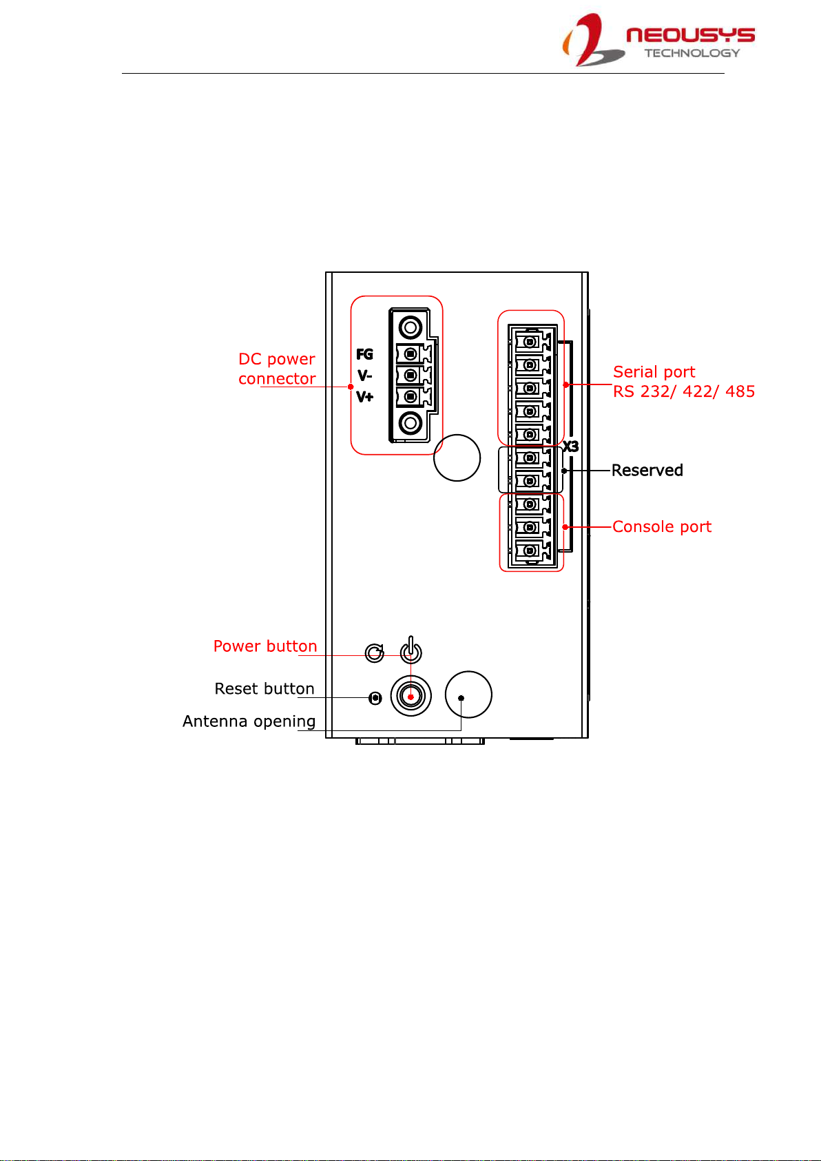
2.6 IGT-33V/ IGT-34C Top Panel
Top of the enclosure features a 3-pin DC power connector, 1x RS-232/ 422/ 485, 1x
RS-485, console port, power button, reset button and an antenna opening.
IGT-30 Series
18
3. System LED
The system has 6 user definable LED indicators for users to program accordingly to their
needs. However, there are some LEDs that come with preset default statuses that will be
mentioned in this chapter. Other LEDs you will find on the system include the Ethernet
port and the power status LED.
3.1 Power & System Status LED
There are seven (7) system status LEDs that include a power
status LED and six (6) user programmable LEDs where some
may have predefined settings.
Label Name Status
description
Preset status
PWR Power Green: System
on
Off: System off
Power status indicator with
green color. On if power on, and
off if power off
L0 LED 0 Amber, User
definable
Amber LED. User-defined
behavior. Configured by default
as system heart-beat
L1 LED 1 Amber, User
definable
Amber LED. User-defined
behavior. No default function.
L2 LED 2 Amber, User
definable
Amber LED. User-defined
behavior. Configured by default
as External SD activity.
L3 LED 3 Amber, User
definable
Amber LED. User-defined
behavior. Configured by default
as Internal SD activity.
L4 LED 4 Amber, User
definable
Amber LED. User-defined
behavior. No default function.
L5 LED 5 Amber, User
definable
Amber LED. User-defined
behavior. No default function.

IGT-30 Series
19
3.2 Ethernet Port & LED
The Ethernet port provides network connectivity. In addition to the console port, it is one
of the two ports that may be used for system’s initialization. The LED status indicator light
functions are described as below.
LED indicator Color Status description
Connection status Amber Steady on: Connection established
Blinking: Data activity
Connection Speed Green Steady on: 100Mbps connection established
Off: 10Mbps connection established

IGT-30 Series
20
4. Digital I/O and DC Connector
There are three I/O connectors on IGT-30 series, each serving a different purpose and
function from one another. They consist of digital input/ output, console and serial port.
There is also a DC connector at the top of the system.
4.1 Digital Input Connector (X1) & Pin Definition
X1 connector on the front panel comprises
of ten pins starting with Pin X1.1 from the
top in numeric order downwards to X1.10.
It is dedicated for digital input functions.
IGT-30D/ IGT-31D X1 Pin Definition
Pin Channel Description Pin Channel Description
X1.1 DI_COM Common point of
digital inputs
X1.6 DI_3 Digital input 3
X1.2 DRY_COM Common point of dry
contact inputs. Modify
corresponding DIP
switches to enable dry
contact input.
X1.7 DI_4 Digital input 4
X1.3 DI_0 Digital input 0 X1.8 DI_5 Digital input 5
X1.4 DI_1 Digital input 1 X1.9 DI_6 Digital input 6
X1.5 DI_2 Digital input 2 X1.10 DI_7 Digital input 7
This manual suits for next models
2
Table of contents
Other Neousys Gateway manuals

Popular Gateway manuals by other brands

JVA
JVA PTE0320 quick start guide

IFM Electronic
IFM Electronic AS-i DP Series Device manual

Motorola
Motorola SVG2500 SURFBOARD DIGITAL VOICE WIRELESS GATEWAY - annexe... Guia do usuário

Motorola
Motorola NETOPIA 2210-02 user manual

MSA
MSA FieldServer FGFD ProtoAir operating manual

scigiene
scigiene RFR-0526-2 user guide


