iLumin SI-2 User manual
SI-2 System Integrator
Installation guide
SI-2-NA


P1
Contents
Introduction 2
Welcome 2
Supplied parts 2
Dimensions 2
Ambient atmosphere requirements 2
Connections 3
iCANnet wiring 3
iCANnet announce button 3
iCANnet termination 3
Serial device connection 4
Operation indicators 4
Programming 5
Adding the SI-2 to iCANsoft 5
The SI-2 conguration window 5
Viewing SI-2 details in iCANsoft 5
RS232 communication settings 6
Startup action 7
Input strings 8
Input actions 9
Output strings 10
Output actions 11
Sequences 12
Diagnostics 13
Appendix 1 14
ASCII Virtual Control Messages 14

P2
Introduction
Welcome
The SI-2 System Integrator provides a vital link point
between any iCANnet network and a third party device
such as an audio visual unit. The compact SI-2 System
Integrator provides a 5-way connector block at one end
for the iCANnet link and a 9-pin D-type female socket
at the other end for the RS232 serial connection to the
third party device.
Using the intuitive iCANsoft application, you can pro-
gram the SI-2 to search for particular actions or mes-
sages received from other control units attached to the
iCANnet network. When a received action or message
matches a stored template, the SI-2 will send a control
message to the device connected via the serial port.
Similarly, the SI-2 also monitors messages being sent
back from the connected serial device and when any of
those messages match those stored within its memory,
a range of actions can be triggered on the iCANnet
network.
The SI-2 System Integrator can store up to 100 input
and output messages together with their related actions.
Additionally, the SI-2 can store up to 16 sequences,
each of which can comprise up to 128 separate steps to
allow multiple actions to be triggered by a single com-
mand.
Supplied parts
Serial connection
to device
Dimensions
iCANnet connection
to network
Ambient atmosphere requirements
Temperature 00C to +400C (320F to 1040F)
Humidity 0 to 95% non-condensing
1.97 in.
(50 mm)
0.6 in.
(15 mm)
0.4 in.
(10 mm)
0.9 in.
(23 mm)
4.88 in.
(124 mm)
4.40 in.
(112 mm)
0.24 in.
(6 mm)
0.24 in.
(6 mm)
Note: All mounting
holes are 4mm (0.15
in.) diameter. The two
outer holes at either
end allow you to
attach the unit using
plastic ties.
P3
Cable type: Cooper LC or CAT 5
Maximum cable length: 1000 ft. (305 m) *
Devices per segment: 100 (without bridge or repeater)
Connections
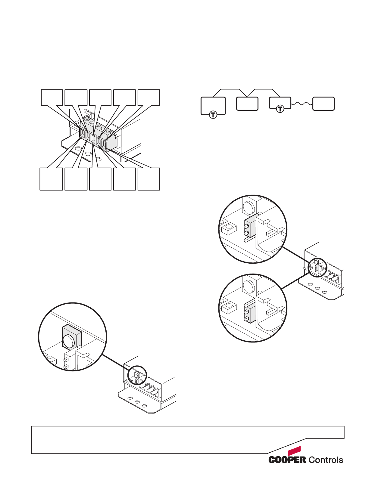
iCANnet wiring
Cable connections to the iCANnet network are made to
a removable 5-way connector block located at one end
of the SI-2 unit:
Termination off
Termination on
iCANnet termination
The iCANnet link is a ‘daisy chain’ protocol that requires
termination on the devices located at either end of the
iCANnet chain.
The SI-2 unit is supplied with termination enabled as
standard. If it is not connected as an end device in the
iCANnet chain, you need to disable termination.
Note: The connection to the serial device is treated
separately and has no impact on whether or not the SI-2
should be terminated.
To disable SI-2 termination, move the jumper from the
lower two pins to the upper two pins, as shown here:
iCAN
Device
iCAN
Device
Serial
Device
SI-2
iCANnet announce button
The SI-2 unit features a small button adjacent to the
green connector which can be used to add the device to
an iCANnet network. When pressed, the SI-2 will send
an announcement message across the iCANnet net-
work. Please see the section ‘Adding the SI-2 to
iCANsoft’ for more details.
0V
(black)
0V
(Green
pair)
CAN-L
(blue)
CAN-L
(Blue)
DRAIN
(gray)
DRAIN
(Brown
pair)
+12V
(red)
+12V
(orange
pair)
CAN-H
(white)
CAN-H
(Blue/
white)
Cooper
LC cable
CAT 5
cable
* A maximum segment distance of 3200 ft. (1000 m) is possible if an
additional 12V power supply is used.
Table of contents


