Image Industries QuikLinx SW750 User manual
Operation Manual
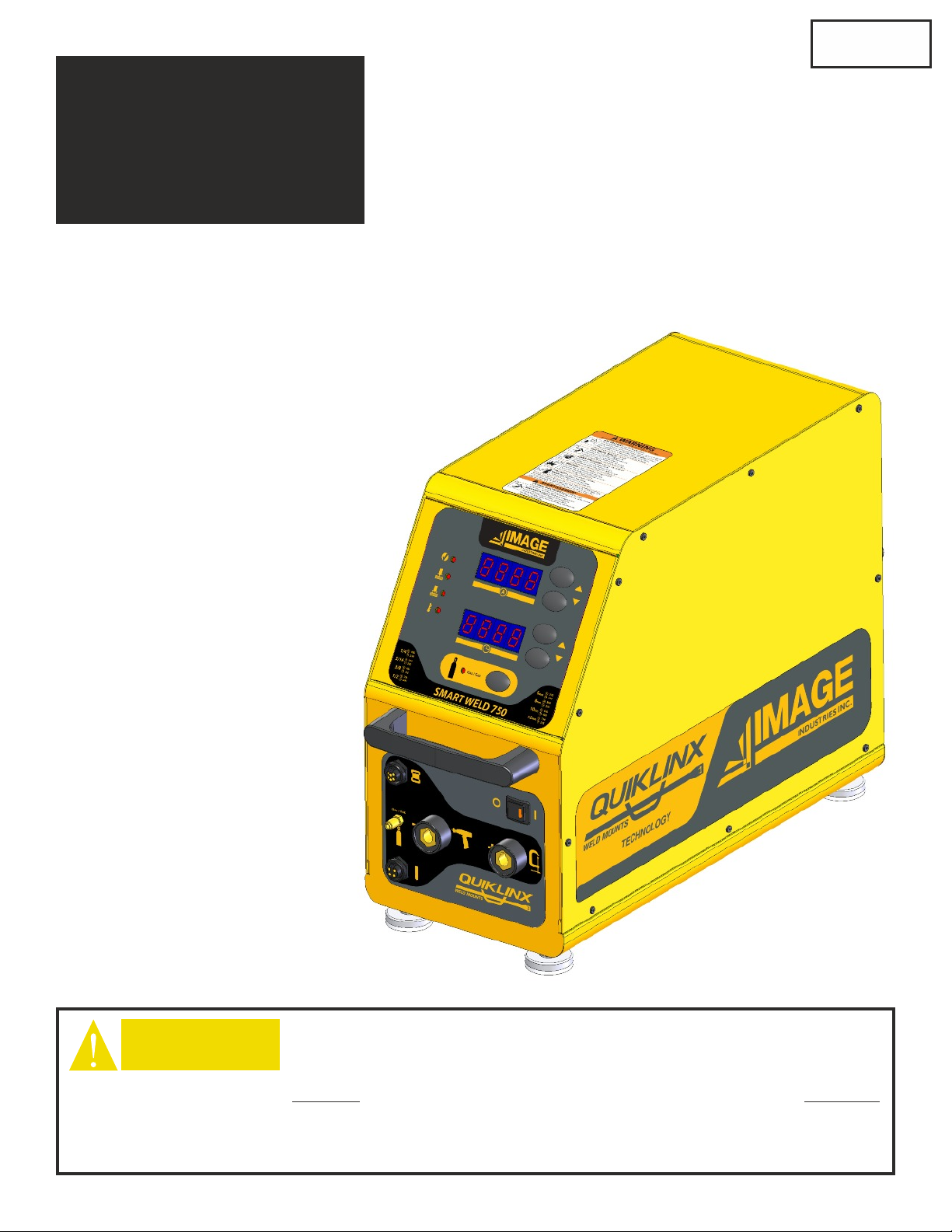
QuikLinx Drawn Arc Stud Welding Power Source
SW750 Single Output
For firmware version 2.0 and later
For serial number C6SA001 and higher
Mfg. after 07-01-2016
CAUTION THESE INSTRUCTIONS ARE FOR EXPERIENCED OPERATORS. If you are not fully
familiar with the principles of operation and safe practices for arc welding equipment, we urge you to
read AWS SP - “Safe Practices” available from the American Welding Society.
DO NOT permit untrained persons to install, operate, or maintain this equipment. DO NOT
attempt to install or operate this equipment until you have read and fully understand these
instructions. If you do not fully understand these instructions, contact your supplier for further
information. Be sure to read the Safety Precautions before installing or operating this equipment.
BE SURE THIS INFORMATION REACHES THE OPERATOR. EXTRA COPIES ARE AVAILABLE THROUGH YOUR SUPPLIER.
CAUTION
P/N 10840-A
August 2017
Price $10.00

Unpacking
11
WARNING
The unit is shipped bolted to a pallet with 3/8-16 bolts. Use a 9/16 or adjustable wrench to unbolt the
power source from the pallet.
There is a foot kit (4 feet) included with the shipment in a separate box.
These feet MUST be installed. The power source takes in cool air from
the the bottom pan. If no feet are installed the unit will not properly cool
and can overheat. The feet install into the same 4 holes used to secure
the power source to the pallet.
The feet may be screwed in until they stop or at any level the user chooses to adjust height.

Table of Contents
2
SECTION 1: Safety Precautions 3
SECTION 2: Installation & Set Up 9
SECTION 3:Normal Operation 15
Advanced Features 18
SECTION 4: Special Techniques 21
SECTION 5: Trouble Shooting 25
SECTION 6: System Maintenance 26
SECTION 7: Exploded Diagram 27
SECTION 8: Parts List 33
SECTION 9: Schematic Diagram 34
W A R R A N T Y
Image warrants that the goods sold will be free from defects in workmanship and material. This warranty is
expressly in lieu of other warranties, expressed or implied or for fitness for a particular purpose. The liability shall
arise only upon return of the defective goods at Buyer’s expense after notice to Image. The warranty shall be
limited to replacement with like goods or, at Image’s option, to refunding the purchase price or repair. Image will
not accept receipt of equipment returned unless buyer has previously afforded Image’s personnel a reasonable
opportunity to inspect and repair said equipment. Image will warrant for 1 year from date of shipment. Image shall
not be liable for any consequential damages including improper set up by customer.
Section 1 Safety Precautions
33
US ERS RESPO NSIBI LITY
This equipment will perform in conformity with the description contained in this manual and accompanying labels and/or
inserts when installed, maintained and repaired in accordance with the instructions provided. This equipment must be checked
periodically. Defective equipment should not be used. Parts that are broken, missing, worn, distorted or contaminated
should be replaced immediately. Should such repair or replacement become necessary, the manufacturer recommends
that a telephone or written request for service advice be made to the Authorized Distributor from whom purchased.
This equipment or any of it’s parts should not be altered without the prior written approval of the manufacturer. The user
of this equipment shall have the sole responsibility for any malfunction which results from improper use, faulty maintenance,
damage, improper repair or alteration by anyone other than the manufacturer or a service facility designated by the
manufacturer.
This symbol appearing throughout this manual means
ATTENT ION! BE ALERT!
Your safety is involved.
The following definitions apply to DANGER, WARNING, CAUTION
found throughout this manual.
DANGER
Used to call attention to immediate hazards
which, if not avoided, will result in
immediate, serious personal injury or loss
of life.
Used to call attention to potential hazards
which could result in personal injury or lost
of life.
Used to call attention to hazards which
could result in minor personal injury.
DANGER
CAUTION
WARNING
WARNING: These Safety Precautions are for your protection.
They summarize precautionary information from the references
listed in the Additional Safety Information section. Before
performing any installation or operating procedures, be sure to
read and follow the safety precautions listed below as well as all
other manuals, material safety data sheets, labels, etc. Failure to
observe Safety Precautions can result in injury or death.
WARNING

Safety Precautions
Section 1
4
ARC RAYS CAN BURN EYES AND SKIN -
The arc, like the sun, emits ultraviolet and infrared (visible and
invisible) and other radiation and can injure skin and eyes. Sparks
and hot metal can fly off the weld. Training in the proper use of
the processes and equipment is essential to prevent accidents.
Therefore:
1) Always wear safety glasses with side shields in any work area, even if wearing a
welding helmet, face shields and goggles are also required.
2) Always use a face shield fitted with the correct shade of filter to protect your
face and eyes when welding or watching (See ANSI Z49.1 and Z87.1 listed
in Safety Standards). Cover sparks and rays of the arc when operating or
observing operations.
3) Use protective non-flammable screens or barriers to protect others from
flash and glare. Warn bystanders not to watch the arc and not to expose
themselves to the rays of the electric-arc or hot metal.
3) Wear flameproof gauntlet type gloves, heavy long-sleeve shirt, cuffless trousers,
high topped shoes, and a welding helmet or cap for hair protection, to protect
against arc rays and hot sparks or hot metal. A flameproof apron may also be
desirable as protection against radiated heat and sparks.
4) Hot sparks or metal can lodge in rolled up sleeves, trousers cuffs or pockets.
Sleeves and collars should be kept buttoned, and open pockets eliminated from
the front of clothing.
6) Use goggles over safety glasses when chipping slag or grinding. Chipped slag
may be hot and can fly far. Bystanders should also wear goggles over safety
glasses.
EL EC TRI CA L S HO CK -
Contact with live electrical parts and ground can cause severe
injury or death. The electrode (the weld stud and chuck) and
work circuit (ground) are electrically live whenever the output is
on. The input power circuit and the machine internal circuits are
also live whenever power is on. Improperly installed or
improperly grounded equipment is a hazard.
1) Disconnect input power before installing or servicing this equipment. Lock-
out/tagout input power according to OSHA 29 CFR 1910.147 (see Safety
Standards).
2) Do not touch live electrical parts. Do not touch the electrode (stud) if you
are in contact with the work, ground, or another electrode from a different
machine.
3) Be sure the power source frame (chassis) is connected to the ground system
of the input power.
4) When making input connections, attach proper grounding conductors first and
then double-check connections.
5) Always verify the supply ground - check and be sure that input power cord
ground wire is properly connected to ground terminal in disconnect box or
that cord plug is connected to a properly grounded receptacle outlet.
6) Refer to ANSI/ASC Standard Z49.1 (listed on page 6) for specific grounding
recommendations. Do not mistake the work lead for a ground cable.
7) Clamp work cable with good metal-to-metal contact (spring and/or magnetic
clamps are not recommended) to work piece as near the weld as practical.
8) DO NOT use welding current in damp areas, if movement is confined, or if
there is danger of falling.
9) Properly install and ground this equipment according to this Owner’s Manual
and national, state and local codes.
10) Connect the work cable to the work piece. A poor or missing connection can
expose you or others to a fatal shock.
11) Keep everything dry, including clothing, work area, cables, torch/electrode
holder and power source.
12) Wear dry, hole-free insulated gloves & body protection before turning on
power.
13) Insulate yourself from work and ground using dry insulating mats or covers big
enough to prevent any physical contact with the work or ground.
14) Don’t stand directly on metal or the earth while working in tight quarters or a
damp area; stand on dry boards or an insulating platform and wear rubber-
soled shoes.
15) Turn off all equipment when not in use.
16) Use well-maintained equipment. Frequently inspect input power cord and out-
put weld cables for damage or bare wiring. Replace worn or damaged cables
immediately; bare wiring can kill. Repair or replace damaged parts at once.
Maintain this unit according to the manual.
17) Do not use worn, damage, undersized or poorly spliced cables.
18) Do not drape cables over your body.
19) If earth grounding of the work piece is required, use a separate cable.
20) Wear a safety harness if working above floor level.
21) Keep all panels and covers securely in place.
22) Insulate work clamp when not connected to work piece to prevent contact
with any metal object.
23) Don’t connect multiple electrodes or work cables to a single weld output
terminal.
SIGNIFICANT DC VOLTAGE exists after removal of the input power on
inverters. Turn off inverter, disconnect input power, and discharge input
capacitors according to instructions in Maintenance Section before touching
any parts.
EL EC TRI C AND M A G NETI C FIE LD S -
Electric and Magnetic Fields may be dangerous. Electric current
flowing through any conductor causes localized Electric and
Magnetic Fields (EMF). Welding and cutting current creates EMF
around welding cables and welding machines.
Therefore:
1) Welders having pacemakers should consult their physician before welding.
EMF may interfere with some pacemakers.
2) Exposure to EMF may have other health effects which are unknown.
3) Welders should use the following procedures to minimize exposure to EMF:
A) Route the electrode and work cables together. Secure them with tape
when possible.
B) Never coil the torch or work cable around your body.
C) Do not place your body between the torch and work cables. Route
cables on the same side of your body.
D) Connect the work cable to the work piece as close as possible to the
area being welded.
E) Keep welding power source and cables as far away from your body as
possible.
FLYING METAL CAN INJURE EYES -
1) Welding, chipping, wire brushing and grinding can cause
sparks and flying metal. As welds cool, they can throw off
slag.
2) Wear approved safety glasses with side shields even under
your welding helmet.
BUILD UP OF GAS CAN INJURE OR KILL -
1) Shut off shielding gas supply when not in use.
2) Always ventilate confined spaces or use approved air-
supplied respirator.

Section 1 Safety Precautions
55
CY LI NDE R HAN DL ING -
Shielding gas cylinders contain gas under high pressure. If
damaged or mishandled a cylinder can explode and violently
release gas. Sudden rupture of cylinder, valve, or relief
device can injure or kill. Since gas cylinders are normally
part of the welding process, be sure to treat them carefully.
Therefore:
1) Protect compressed gas cylinders from excessive heat, mechanical shocks,
slag, open flames, sparks and arcs.
2) Keep cylinders away from any welding or other electrical circuits
3) Never drape a welding tool over a gas cylinder
4) Never allow a welding electrode (weld stud) to touch any cylinder
1) Use the proper gas for the process and use the proper pressure reducing
regulator, hoses and fittings designed to operate from the specific
compressed gas cylinder. Do not use adaptors. Maintain hoses and fittings
and other associated parts in good condition.
2) Always secure cylinders in an upright position by chain or strap to suitable
hand trucks, undercarriages, benches, walls, post, or racks. Never secure
cylinders to work tables or fixtures where they may become part of an
electrical circuit.
3) When not in use, keep cylinder valves closed. Have valve protection cap in
place if regulator is not connected. Secure and move cylinders by using
suitable hand trucks. Avoid rough handling of cylinders.
4) Locate cylinders away from heat, sparks, and flames. Never strike an arc or
weld on a cylinder; it will explode.
6) Turn face away from valve outlet when opening cylinder valve.
5) For additional information, refer to CGA Standard P-1, “Precautions for Safe
Handling of Compressed Gases in Cylinders”, which is available from
Compressed Gas Association, 1235 Jefferson Davis Highway, Arlington, VA
22202
FU ME S A ND GA SE S -
Welding produces fumes and gases. Breathing these fumes
and gases can be hazardous to your health, particularly in
confined spaces. Do not breathe fumes and gases. Shielding
gases can cause asphyxiation. Therefore:
1) Keep your head out of the fumes. Do not breathe the fumes.
2) If inside, ventilate the area and/or use exhaust at the arc to remove welding
fumes and gases.
3) If ventilation is poor, use an approved air-supplied respirator.
4) Read the Material Safety Data Sheets (MSDS) and the manufacturer’s
instructions for metals, consumables, coatings, cleaners and degreasers.
5) Work in a confined space only if it is well ventilated, or while wearing an
air-supplied respirator. Always have a trained watch-person nearby. Welding
fumes and gases can displace air and lower the oxygen level causing injury or
death. Be sure the breathing air is safe.
6) Don’t weld in locations near degreasing, cleaning or spraying operations. The
heat & rays of an arc can react with vapors to form highly toxic & irritating
gases.
7) Don’t weld on coated metals, such as galvanized, lead or cadmium plated
steel, unless the coating is removed from the weld area, the area is well
ventilated, and if necessary, while wearing an air-supplied respirator. The
coatings and any metals containing these elements can give off toxic fumes if
welded.
8) Do not weld, cut, or gouge on materials such as galvanized steel, stainless
steel, copper, zinc, lead, beryllium or cadmium unless positive mechanical
ventilation is provided. Do not breathe fumes from these materials.
9) If your develop momentary eye, nose, or throat irritation while operating, this
is an indication that ventilation is not adequate. Stop work and take necessary
steps to improve ventilation in the work areas. Do not continue to operate if
physical discomfort persists.
10) Refer to ANSI/ASC Standard Z49.1 for specific ventilation recommendations.
WELDING CAN CAUSE FI RE S A ND
EX PL OSI ON S -
Welding on closed containers, such as tanks, drums or pipes, can
cause them to blow up. Sparks can fly off from the welding arc.
The flying sparks, hot work piece, and hot equipment can cause
fires and burns. Accidental contact of electrode to metal objects
can cause sparks, explosion, overheating or fire. Check and be
sure the area is safe before doing any welding. Therefore:
1) Protect yourself and others from flying sparks and hot metal.
2) Do not weld where flying sparks can strike flammable material.
3) Remove all combustible materials a minimum of 35ft away from the welding
arc or cover the materials with a protective nonflammable covering.
Combustible materials include wood, cloth, sawdust, liquid and gas fuels,
solvents, paints and coatings, paper, etc.
4) Hot sparks or hot metal can fall through cracks or crevices in floors or wall
openings and cause a hidden smoldering fire or fires on the floor below. Make
certain that such openings are protected from hot sparks and metal.
5) Do not weld, cut, or perform other hot work until the work piece has been
completely cleaned so that there are no substances on the work piece which
might produce flammable or toxic vapors.
6) Be aware that welding on a ceiling, floor, bulkhead or partition can cause fire
on the hidden side.
7) Do not weld on closed containers such as tanks, drums or pipes unless they
are properly prepared according to AWS F4.1.
8) Connect work cable to the work as close to the welding area as practical to
prevent welding current from traveling long, possibly unknown paths and
causing electric shock and fire hazards.
9) Do not use welder to thaw frozen pipes.
10) Remove electrode (weld stud) from the stud weld tool when not in use.
11) Remove any combustibles, such as a butane lighter or matches from your
person before doing any welding.
12) Have appropriate fire extinguishing equipment handy for instant use, such as
a garden hose, water pail, sand bucket or portable fire extinguisher. Be sure
you are trained for proper use.
13) Do not use equipment beyond its ratings. For example, overloaded welding
cable can overheat and create a fire hazard.
14) After completing operations, inspect the work area to make certain there are
no hot sparks or hot metal which could cause a later fire. Use fire watchers
when necessary.
15) For additional information, refer to NFPA Standard 51B, “Fire Prevention
in Use of Cutting and Welding Processes,” available from the National Fire
Protection Association, Batterymarch Park, Quincy, MA 02269
NOISE CAN DAMAGE HEARING -
Noise from some processes or equipment can damage hearing.
1) Wear approved ear protection if noise level is high
FIRE OR EXPLOSION HAZARD -
1) Do not install or place unit on, over, or near combustible
surfaces.
2) Do not install unit near flammables.
3) Do not overload electrical wiring - be sure power supply
system is properly sized, rated and protected to handle the
unit.

Safety Precautions
Section 1
6
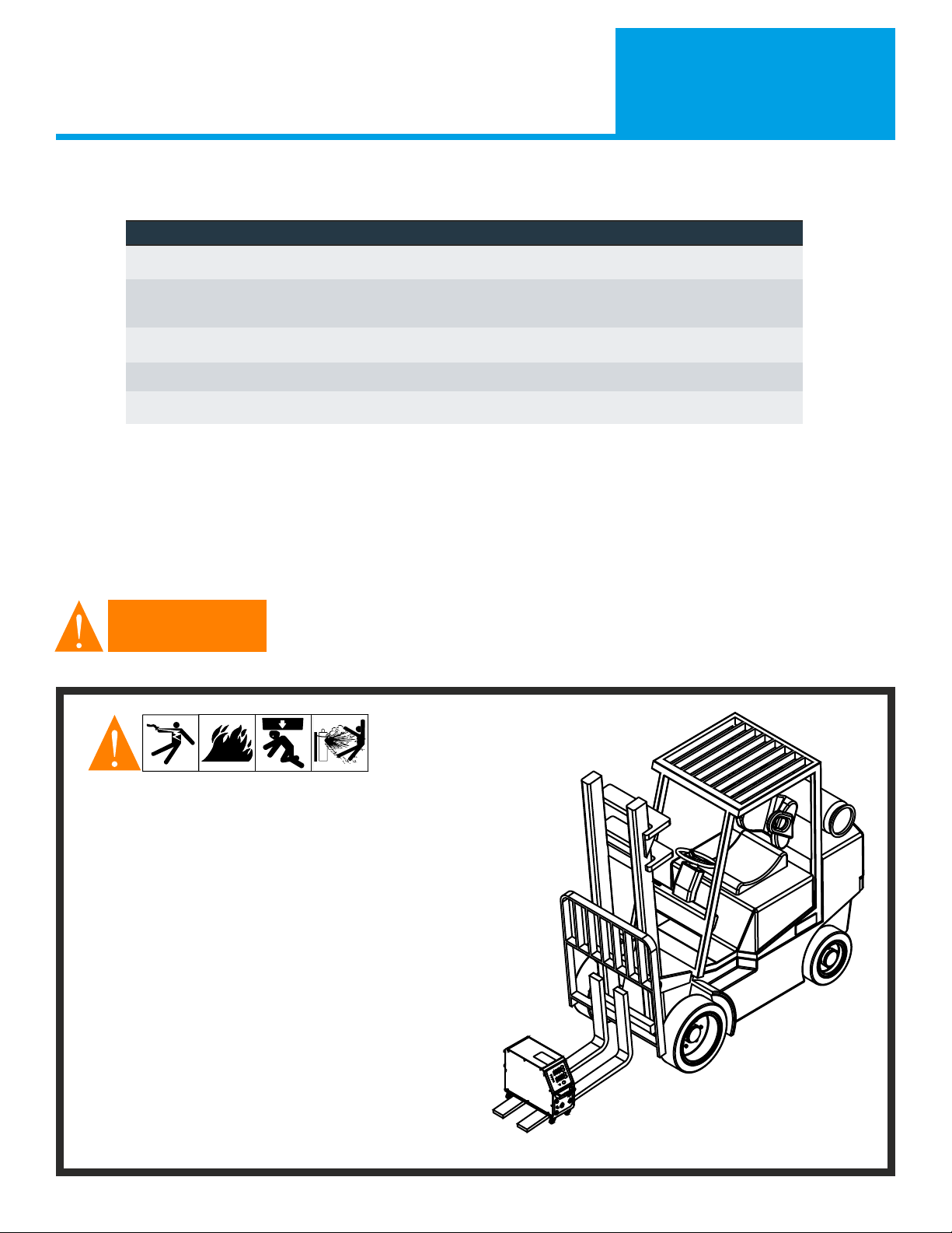
FALLING UNITS CAN CAUSE INJURY -
1) Use lifting aid to lift unit from bottom or handles, NOT
running gear, gas cylinders or any other accessories.
2) Use equipment of adequate capacity to lift and support unit.
3) If using lift forks to move unit, be sure forks are long enough
to extend beyond opposite side of the unit.
OVERUSE CAN CAUSE OVERHEATING -
1) Allow cooling period; follow rated duty cycle.
2) Reduce current or reduce duty cycle before starting to weld
again.
3) Do not block or filter airflow to unit
STATIC (ESD) CAN DAMAGE PC BOARDS -
1) Put on grounded wrist strap BEFORE handling boards or
parts.
2) Use proper static-proof bags and boxes to store, move or
ship PC boards.
MOVING PARTS CAN CAUSE INJURY -
1) Keep hands, hair, loose clothing and tools away from
moving parts such as fans and pinch points such as drive
rolls.
2) Keep all doors, panels, covers and guards closed and
securely in place.
3) Always disconnect electrical power prior to service to
prevent the fan from starting unexpectedly.
WELDING WIRE CAN CAUSE INJURY -
1) Do not press weld tool (gun) trigger until instructed to do
so.
2) Do not point weld tool toward any part of the body, other
people or any metal when threading welding wire.
H.F. RADIATION CAN CAUSE INTERFERENCE -
1) High-Frequency (H.F.) can interfere with radio navigation,
safety services, computers and communications equipment.
2) Have only qualified persons familiar with electronic
equipment perform this installation.
3) The user is responsible for having a qualified electrician
promptly correct any interference problem resulting from the
installation.
4) If notified by the FCC about interference, stop using the equipment at once.
5) Have the installation regularly checked and maintained.
6) Keep high-frequency source doors and panels tightly shut, keep spark gaps at
correct setting, and use grounding and shielding to minimize the possibility of
interference.
ARC WELDING CAN CAUSE INTERFERENCE -
1) Electromagnetic energy can interfere with sensitive electronic
equipment such as computers and computer-driven
equipment such as robots.
2) Be sure all equipment in the welding area is electro-
magnetically compatible.
3) To reduce possible interference, keep weld cables as short as
possible, close together, and down low, such as on the floor.
4) Locate welding operation 100 meters from any sensitive electronic equipment.
5) Be sure this welding machine is installed and grounded according to this
manual.
6) If interference still occurs, the user must take extra measures such as moving
the welding machine, using shielded cables, using line filters, or shielding the
work area.
EMF Information
Considerations about welding and the effects of low frequency Electric and Magnetic
Fields (EMF):
Welding current, as it flows through welding cables, will create electromagnetic
fields. There has been and still is some concern about such fields. However, after
examining more than 500 studies spanning 17 years of research, a special blue ribbon
committee of the National Research Council concluded that: “The body of evidence,
in the committee’s judgement, has not demonstrated that exposure to power-
frequency electric and magnetic fields is a human-health hazard.” However, studies
are still going forth and evidence continues to be examined. Until the final
conclusions of the research are reached, you may wish to minimize your exposure to
electromagnetic fields when welding or cutting. See section on EMF on page 4.
HOT PARTS CAN CAUSE SEVERE BURNS -
1) Do not touch hot parts with bare hands.
2) Allow cooling period before working on welding tool (weld
tool or torch).
EQ UI PME NT MA IN TEN AN CE -
Faulty or improperly maintained equipment can cause injury or
death. Therefore:
1) Always have qualified personnel perform the installation,
troubleshooting, and maintenance work. Do not perform
any electrical work unless you are qualified to do the work.
2) Before performing any work inside a power source, disconnect the power
source from the incoming electrical power using the disconnect switch at the
fuse box before working on the equipment.
3) Maintain cables, grounding wire, connections, power cord, and power supply
in safe working order. Do not operate any equipment in faulty condition.
4) Do not abuse any equipment or accessories. Keep equipment away from: -
heat sources such as furnaces
- wet conditions such as water puddles and inclement weather -
oil or grease
- corrosive atmospheres.
5) Keep all safety devices and cabinet covers in position and in good repair.
6) Use equipment only for its intended purpose. Do not modify it in any
manner.

Section 1 Safety Precautions
77
AD DITIONAL SA FETY INFORMA TION -
For more information on safe practices for electric arc welding refer to the following publications:
American Welding Society
550 N.W. LeJuene Road, Miami, FL 33126, (phone 305-443-9353, website: www. aws.org)
1) ANSI/ASC Z49.1 - Safety in Welding, Cutting and Allied Processes
2) AWS CH5 - Recommended Practices for Stud Welding
3) AWS D1.1 - Structural Welding
2) AWS C5.1 - Recommended Practices for Plasma Arc Welding
3) AWS C5.6 - Recommended Practices for Gas Metal Arc Welding
4) AWS SP - Safe Practices - Reprint, Welding Handbook.
5) ANSI/AWS F4.1, Recommended Safe Practices for Welding and Cutting of Containers and Piping.
National Fire Protection Association
P.O. Box 9101, 1 Battery March Park, Quincy, MA 02269-9101 (phone 617-770-3000, website: www.nfpa.org and sparky.org)
1) NFPA Standard 70 - National Electrical Code
2) NFPA Standard 51B - Standard for Fire Prevention During Welding, Cutting and Other Hot Work
Compressed Gas Association
1735 Jefferson Davis Highway, Suite 1004; Arlington, VA 22202-4102 (phone 703-412-0900, website: www.cganet.com)
1) CGA Pamphlet P-1 - Safe Handling of Compressed Gas Cylinders
Canadian Standards Association
Standards Sales, 178 Rexdale Blvd, Rexdale, Ontario, Canada M9W 1R3 (phone 800-463-6727 in Toronto 416-747-4044, website: www.csa-international.org)
1) CSA Standard W117.2 - Code for Safety in Welding and Cutting
American National Standards Institute
11 West 42nd Street, New York, NY 10036-8002 (phone 212-642-4900, website: www.ansi.org)
1) ANSI Standard Z87.1 - Practice for Occupational and Educational Eye and Face Protection
U.S. Government Printing Office
Superintendent of Documents, P.O. Box 371954, Pittsburgh, PA 15250 (phone 312-353-2220, website: www.osha.gov)
1) Title 29, Code of Federal Regulations (CFR), Part 1910, Subpart Q, & Part 1926, Subpart J - Occupational Safety and Health Standards for General Industry
This power source may or may not contain a battery which may contain hazardous materials. Please follow local
battery disposal procedures when changing batteries or disposing of the power supply.
California Proposition 65 Warnings
Welding or cutting equipment produces fumes or gases which contain chemicals known to the State of Cali-
fornia to cause birth defects and , in some cases, cancer. (California Health & Safety Code Section 25249.5 et
seq.)
Battery posts, terminals and related accessories contain lead and lead compounds, chemicals known to the
State of California to cause cancer and birth defects or other reproductive harm. Wash hands after handling.
For Gasoline Engines:
Engine exhaust contains chemicals known to the State of California to cause cancer, birth defects, or other
reproductive harm.
For Diesel Engines:
Diesel engine exhaust and some of its constituents are known to the State of California to cause cancer, birth
defects, and other reproductive harm.

Safety Precautions
Section 1
8
Symbols and Definitions

Installation & Set Up
Section 2
99
General Description
Specification
Dimensions H: 19.2”; 488 mm (including feet) W: 10.49”; 266 mm L: 26.9”; 683 mm (Including handles)
Weight Not including guns and cables 172lbs (78kg)
North America Supply Voltage 230 V 3 phase 460 V 3 phase 575 V 3 Phase
Welding Capability
Model Inch capacity Metric Capacity QuikLInx
SW750 1/2” 13mm All styles of QuikLinx Clips
Intended Usage
This power source supports welding QuikLinx clips with the autofeed Quicklinx tool.
This power source also supports welding standard arc studs using a standard draw arc weld tool in accordance with
AWS C5H; AWS D1.1; ISO14555 and CSA W59
This power source does NOT support both types of tools at the same time.
Duty Cycle
Power source is rated at a 5% duty cycle. The unit can deliver the full rated
current for 1 full second on; followed by 19 seconds off. While it is possible
to deviate from this specific duty cycle (i.e. short rapid bursts or welds
lasting longer that 1 second) the off time must be adjusted accordingly
or the unit will go into thermal shut down.
Storage and Operating Environment
• The Power Supply or Welding Unit should be located on
a flat, level floor: It should not be tilted more than 15°
in any direction during operation and/or
transportation. Unit may tip if tilted in excess
of the 15° maximum.
• Near the work area to limit welding cable
length (shorter lengths are preferred).
• In a dry area away from moisture.
• Placed to protect it from grinding dust and
other contaminates.
• To provide minimum of 12” clearance on all sides for cooling.
• The factory equipped feet are not removed (again for cooling).
12 inch (300 mm)
12 inch (300 mm) Feet must be in place
for proper cooling.
Installation & Set Up
Section 2
10
Operating Environment Storage Environment
Temperature -20°C to +40°C (15°F to 104°F) -25°C to +55°C (-15°F to 131°F)
Humidity
H%<=50% at 40°C(104°F)
H%<=90% at 20°C(68°F)
H%<=50% at 40°C(104°F)
H%<=90% at 20°C(68°F)
Ambient Air Free from excessive dust, acids, corrosive gasses or substances etc.
Altitude ASL<=1,000m(3,280Ft) ASL<=1,000m(3,280Ft)
Incline 15° Maximum Incline 15° Maximum Incline
Environmental Conditions
Welding power sources shall be capable of delivering their rated output when the following environmental conditions prevail
Handling Instructions
Mass of the SW750 and its various parts require correct methods of handling them, e.g. by fork-lift.
Unit should not be moved with cables attached. Remove all cables before transporting unit (ground, gun, incoming power).
Unit SHOULD NOT be moved with gas cylinders. Detach and move gas cylinders separately.
WARNING
If using lifting forks, extend forks beyond opposite side of
unit. Locate unit near correct input power supply.
Special installation may be required
where gasoline or volatile liquids are present.
See NEC Article 511 or CEC Section 20.
Caution When Moving
Installation & Set Up
Section 2
1111
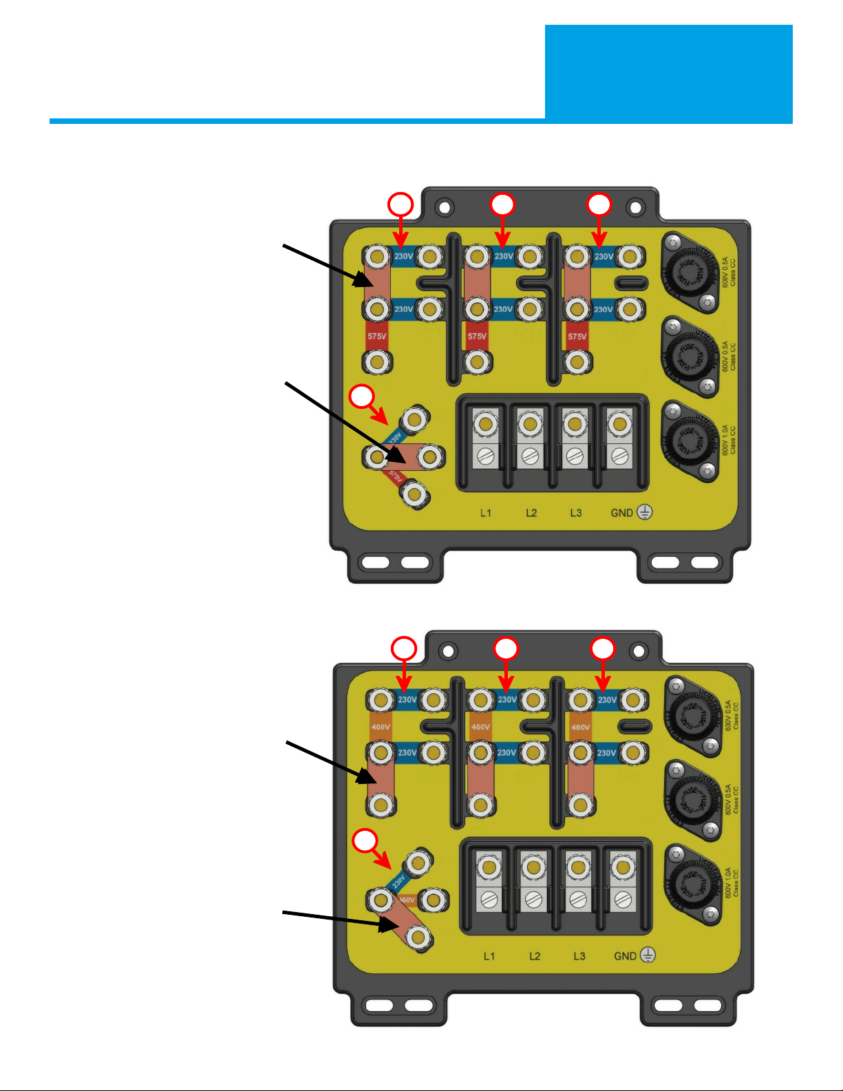
RECOMMENDED WIRING SEQUENCE
1. Set the power source jumper links to match
incoming voltage.
2. Connect the incoming power leads to the welding
power source.
3. Connect the incoming cable to the disconnect box.
4. Connect the weld ground and cables.
SETTING JUMPER LINKS
There are several jumper links that must be set before
connecting electrical power to the welder for both the
main transformer and control transformer. Always verify
jumper settings before connecting electrical power to
any device. Use 7/16 socket wrench or nut driver to
ensure the jumper link nuts are tight.
JUMPER LINK LOCATION
Use a straight blade screwdriver to turn the access panel
latch to the vertical position. The door will be able to
be opened. When finished, close the access panel door
and using a screw driver turn the latch to the horizontal position to lock the door closed.
B
2 Separate Jumper Links for 230V
3 Places A, B, C
A C
D
1 Jumper Link for 230V
1 Place D (Top Position)
Jumper Panel
Access Door
Rear of the
Power Source
Installation & Set Up
Section 2
12
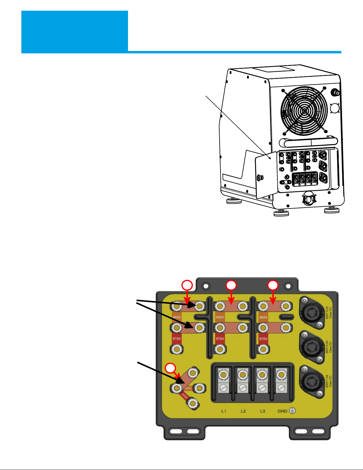
460V JUMPER LINK CONFIGURATION
575V JUMPER LINK CONFIGURATION
B
1 Jumper Link for 460V
(Links may be stacked for storage)
3 Places A, B, C
A C
D
1 Jumper Link for 460V
1 Place D (Mid Position)
B
1 Jumper Link for 575V
(Links may be stacked for storage)
3 Places A, B, C
A C
D
1 Jumper Link for 575V
1 Place D (Lower Position)
Installation & Set Up
Section 2
1313
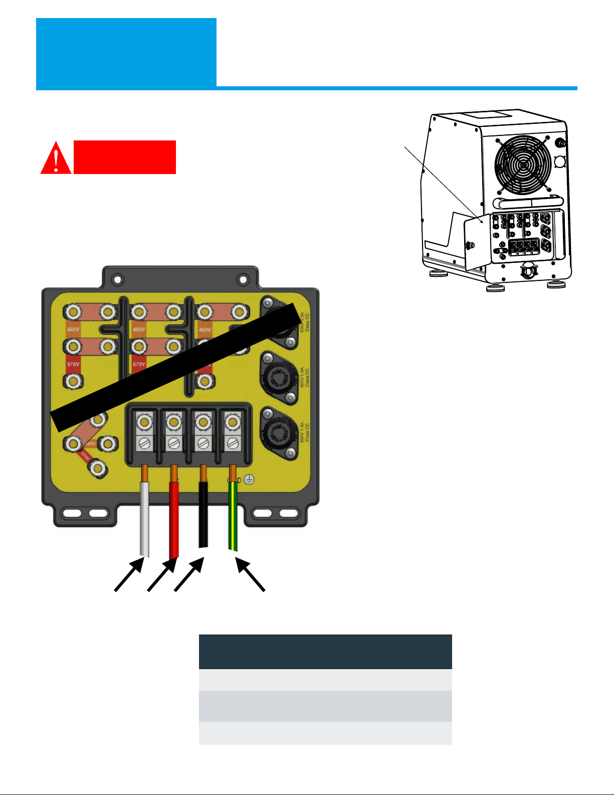
Connecting Incoming Power
To connect incoming electrical power
it is necessary to open the electrical
access panel on the rear of the power
source. Use a straight blade
screwdriver to turn the access panel latch to the vertical position. The
door will be able to be opened. When finished close the access panel
door and using a screw driver turn the latch to the horizontal position
to lock the door in a closed position.
Strip back the outer cable jacketing so there is
approximately 5” (125mm) of insulated leads. Strip
approximately ½” (12mm) of insulation on each
conductor. Thread the 4 leads through the cord grip
on the lower center back of the back of the welder.
Connect the ground lead to the identified ground lug
first.
Use the provided lugs to secure this lead. Connect
the incoming wires to L1, L2 and L3 as shown in the
picture on the left. Use a large flat bladed
screwdriver to secure the incoming leads to the lugs.
These connections should be tight. Tighten cord grip
onto incoming cable jacket.
When complete, close the rear access door, turn the
latch to secure and connect the incoming power
cable to the disconnect box or outlet.
DANGER
L1 L2 L3 Ground
Jumper Links shown in 230V Configuration
Your L1, L2 & L3 colors may vary.
L1, L2 & L3 order (rotation) does not matter
Voltage Recommended
Fusing (Delay Type)
Minimum Copper Line
& Ground Wire Size
90°C THHN Copper
230 60 Amp 6 gauge
460 30 Amp 10 gauge
575 20 Amp 12 gauge
Jumper Panel
Access Door
Rear of the
Power Source
Installation & Set Up
Section 2
14
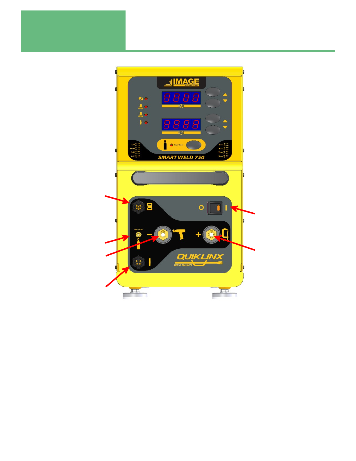
Controls Diagram
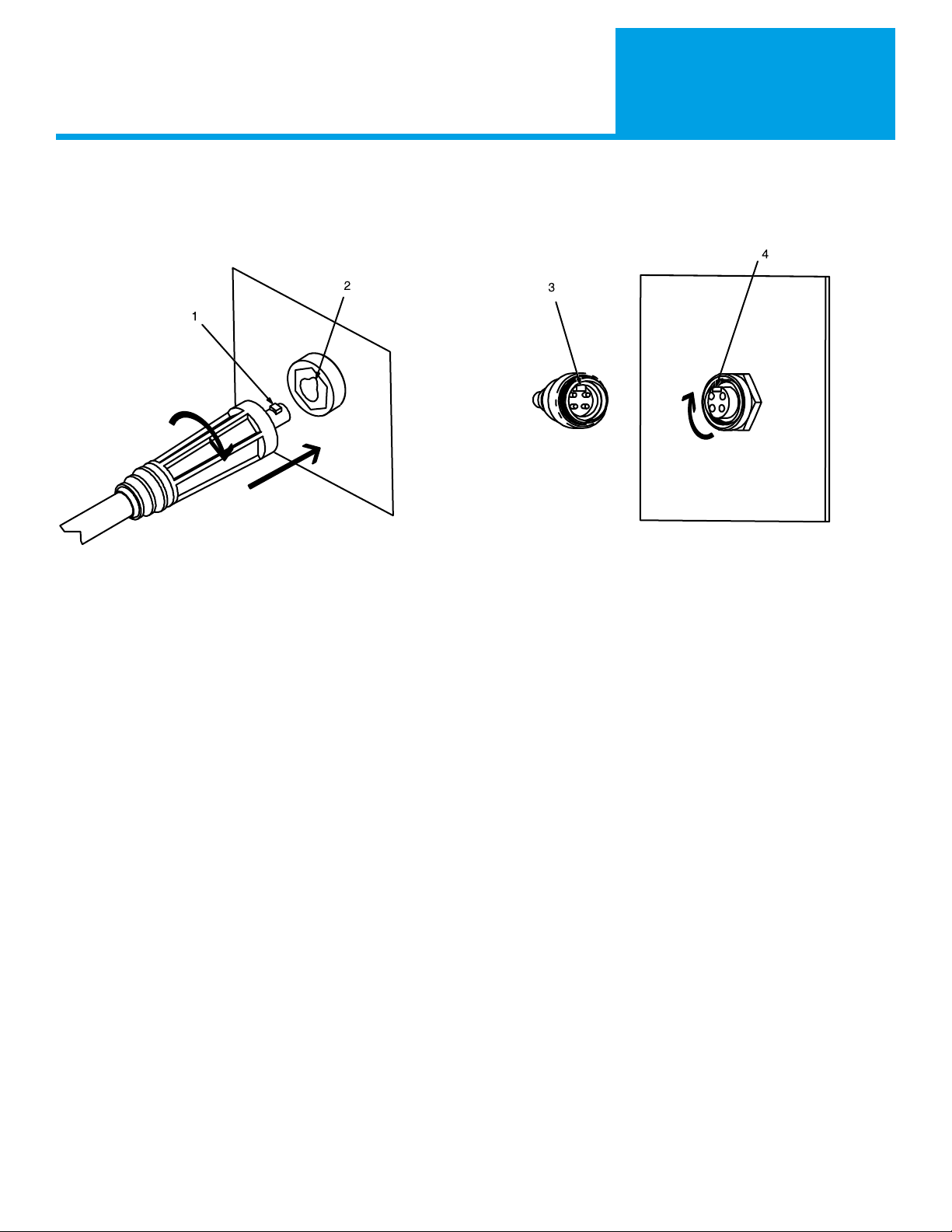
CONNECTING THE GROUND AND WELD CABLES
GROUND AND WELD CABLE
1. Line up the key (item 1) on the connector on the end of the ground cable with the key way (item 2).
2. Push the connector into the receptacle until the rubber of the connector meets the housing of the receptacle.
3. Turn the connector clockwise until it stops.
Repeat with the weld cable. To remove, reverse the steps above.
CONTROL CABLE
4. Line up the key (item 3) on the connector on the end of the gun control cable with the key way (item 4).
5. Push the connector into the receptacle until the threads of the connector meet the threads of the receptacle.
6. Thread the connector clockwise until it stops. Finger tight is sufficient. DO NOT OVER TIGHTEN.
To remove, reverse the steps above.
Key Key
Key way
Weld & Ground Cable Connections
Key way
Control Cable Connections
Normal Operation
Section 3
15
NOTE: This QuikLInx Stud Weld power source is unique in that it can weld both QuikLinx cable management
clips and weld standard threaded weld studs. QuikLinx clips and threaded studs require different weld tools.
Both weld tools CANNOT be connected at the same time
POWER UP
Once all the set up from section 2 has been completed the welder may be powered up.
Press (to the right or towards the 1) and momentarily hold the power switch, located on the right side of the lower portion
of the welder. The power source initiates a self test. This test lasts approximately 5 seconds. During this test routine none
of the welders’s functions, including welding, will operate. This is normal. During self-test the welder will display the
current revision of software installed.
When self test ends, the welder will display the amperage and time values. The display will automatically show the values for
current and time which are saved from the last time the welder was used. Note: values are ONLY saved after a weld.
QuikLinx
Weld Tool (gun)
Control Connector
Power Switch
Ground Cable Connector
Shielding Gas Connector
Weld Tool (gun)
Weld Cable Connector
Standard Stud
Weld Tool (gun)
Control Connector

Section 3 Normal Operation
16
Current Increase (UP)
Current Decrease (Down)
Time Increase (UP)
Time Decrease (Down)
Gas Mode
Gas Mode Indicator
System Check
Contact with work
Trigger Indicator
Thermal Overload
Push Buttons
The push buttons have an acceleration feature built into them. As you press and hold the buttons, the values change by
greater amounts. For example, you would like to set the welder to 750 amps, but the display is showing 50 amps. By
pressing and holding the current up button the display will jump in large steps towards 750 amps.
Use the push buttons to adjust the current and the time to the desired values for the fastener to be welded.
Use gas if appropriate (light will not be lit if off). Gas is discussed later in this manual.

Normal Operation
Section 3
17
WELD SETTINGS
Recommended Power Source Current & Time Settings for standard arc weld studs
These values are also printed on the front panel for easy reference. These are suggested values. Your circumstances may
require that the values be adjusted up or down to achieve ideal results.
Recommended Power Source Current & Time Settings for QuikLinx
The recommended values for welding QuikLinx clips depend on the type of QuikLinx clip and the welding process being used.
Types of Clips
There are 2 types of clips that can be used with the QuikLinx tool:
Unfluxed 10306MAG Used for Short Cycle Welding or Gas Arc
Fluxed 10450MAG Used for more robust applications and harder to weld materials like HSLA or AR400
Note: These are recommended settings. Your specific circumstance and application may require different settings. Always
test and validate your weld before using in a production scenario.
Checking Weld Quality
The weld quality can best be checked with a torque test. Image offers a torque check attachment (Part number 10441)for a
standard torque wrench. We recommend a maximum torque check value of 30 ftlbs. Beyond 30 ftlbs the wings of the
QuikLinx clip begin to distort.
Type Part Number Process Current (A) Time (Sec)
Un-Fluxed 10306MAG Short Cycle 700 0.200
Un-Fluxed 10306MAG Gas Arc 700 0.400
Fluxed 10450MAG Standard 450 0.400
Type Part Number Process Passing
Torque
Un-Fluxed 10306MAG Short Cycle 20 ftlbs
Un-Fluxed 10306MAG Gas Arc 25 ftlbs
Fluxed 10450MAG Standard 30 ftlbs
Stud Size Current (A) Time (Sec) Stud Size Current (A) Time (Sec)
Unit Min 100 0.05 Unit Max 750 1.500
1/4 400 0.250 6 mm 375 0.230
5/16 500 0.320 8 mm 500 0.320
3/8 600 0.375 10 mm 630 0.400
1/2 750 0.600 12 mm 750 .525

Section 3 Normal Operation
18
STUD WELD TOOL SETTINGS
Standard Draw Arc Weld Tool
The time & current setting in the previous section will vary with the stud weld tool’s lift and plunge settings. Typical values
are 3/32” for weld tool lift and 1/8” for weld tool plunge. For this power supply, stud lift is recommended to be at 3/32”.
QuikLinx Weld Tool
For QuikLinx tool set up, please see the QuikLinx Manual that came with the QuikLinx tool.
WELDING
There are several different stud welding processes that this welder can perform. Be sure that your stud weld tool is set up
properly for the process you intend to use. See Section 4 for discussion of different welding processes.
Position the weld tool against the work. Press down on the stud weld tool to make sure the ferrule or spark shield sits firmly
against the work. While holding the weld tool in position, press the trigger. The weld will initiate (gas flow will start if the gas
mode is enabled) and complete. Continue to hold the weld tool against the work for 1/2 sec to allow the molten metal to
cool. Pull the weld tool off of the stud. This completes a weld sequence.
ADVANCED FEATURES
GAS MODE
The stud welding power supply supports gas arc welding. This mode requires a special stud weld gun that is equipped with the
proper accessories for gas arc stud welding. There are 3 different gas modes and each is indicated differently by the gas mode
indicator light:
Note: On power up, if gas mode is on, the unit will purge the gas lines for 5 seconds.
HAMMER MODE
This mode is most useful when welding on dirty, rusty, mill scale or painted surfaces (painted surfaces require a special stud).
The system automatically detects ground. If ground is not found the weld tool lifts and plunges to break through the scale or
paint. It will repeat this lift/plunge (hammer) sequence until ground is detected at which point the stud will weld. After the
set number of hammers, if the weld has not occurred, the system stops and returns to the ready state.
Gas Mode
Gas Mode
Indicator Light
Gas Function
OFF OFF Shielding Gas is not being used
Per Weld FLASHING The gas pre-flows for .5 seconds. The weld completes and the gas post flows for .5 seconds.
The gas then shuts off. This sequence is followed for each weld.
Continuous ON
For the first weld the gas pre-flows for .5 seconds. The weld completes and the gas continues
to flow. On subsequent welds there is no pre-flow, the weld begins immediately. The gas shuts
off after 20 seconds of inactivity.

Normal Operation
Section 3
19
ADVANCED FEATURES CONTINUED
HAMMER MODE CONTINUED
To enable and adjust the hammer mode you must enter the welder’s parameter adjustment mode.
NOTE: Hammer Mode does NOT apply/work with the QuikLinx tool.
Parameter Adjustment Mode
To enter parameter adjustment mode the user needs to enter the following key sequence within 5 seconds:
Current UP
Time DOWN
Current DOWN
Time UP
The upper display will now show: P1
The lower display will show: off
The Top UP/DOWN Buttons (Current) Changes the Parameter P1 to P2 and so on.
The lower UP/DOWN Buttons (Time) Adjust the parameter value, for example, off to on
Parameters Table
Use the Current buttons to select the parameter you are interested in adjusting. Example P1
Use the time buttons to change the value of the parameter. Example from off to on
You may adjust all parameters this way.
When you have finished adjusting parameters, press the gas button. This will enter the SAVE mode.
Use the time buttons to change from no to Yes.
Press the gas button again to write the new parameters to memory.
If you press the gas button with no as the Save parameter the unit will exit the parameter adjustment mode and no changes
will have been saved.
Lift Check
If the hammer mode is off and the system does not detect ground (i.e. the weld tool is air triggered), the weld tool will cycle
once without welding. This is useful for checking lift settings in the weld tool. If gas flow is enabled, gas will flow during lift
check. This can be used on power up to purge the gas line.
NOTE: Gas does NOT flow during a lift check with the QuikLinx tool.
Parameter Meaning
P1 Hammer Mode on/off
P2 Number of Hammers 1-10
DEF Restore Default Parameters; yes/no
LoC Locks the front panel from changing; on/off
Table of contents
Other Image Industries Welding System manuals


