English English
5
GENERAL DESCRIPTION
General Physical Description
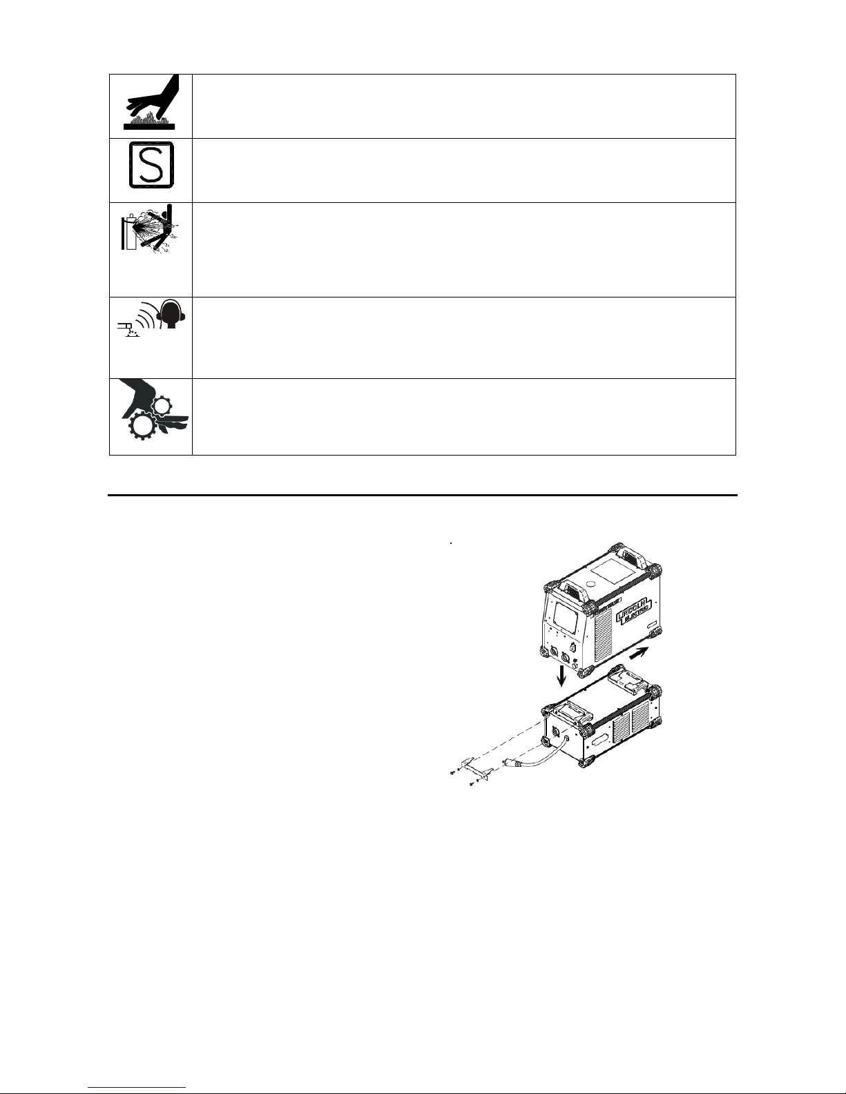
The POWER WAVE® STT® MODULE (CE) is an
accessory enabling compatible power sources to
perform the STT® function without limiting the normal
multi-process rating of the host machine. It is intended
for use with medium range “S”– series Power Wave ®
power sources such as the S350. The module itself is a
low profile pedestal, designed to seamlessly integrate
with compatible power sources and water coolers.
General Functional Description
The POWER WAVE® STT® MODULE (CE) is
essentially a high speed, high capacity output switch,
connected in series with the positive output of the power
source. It communicates module status and identification
information to the power source via the ArcLink®
protocol, and receives a high speed synchronized
switching command via a dedicated digital link.
DUTY CYCLE
The POWER WAVE® STT® MODULE (CE) is rated at
450 amps at a 100% duty cycle. It is further rated to
support 500 amps at a 60% duty cycle and 550 amps at
a 40% duty cycle. The duty cycle is based on a ten-
minute period. A 60% duty cycle represents 6 minutes of
welding and 4 minutes of idling in a ten-minute period.
Note:
The POWER WAVE® STT® MODULE (CE) is capable
of withstanding a peak output current of 750 amps. The
allowable maximum average output current is time
dependant, and ultimately limited by the host power
source.
COMMON WELDING PROCEDURES
MAKING A WELD
Choose the electrode material, electrode size, shielding
gas, and process (GMAW, GMAW-P, GMAW STT etc.)
appropriate for the material to be welded.
Select the weld mode that best matches the desired
welding process. The standard weld set shipped with the
host power source encompasses a wide range of
common processes that will meet most needs. If the STT
modes are not available, or if a special weld mode is
desired, visit www.powerwavesoftware.com or contact
the local Lincoln Electric sales representative.
The power source controls the POWER WAVE® STT®
MODULE (CE) based on the selected weld mode.
For a more detailed description, and specific operating
instructions, consult the power source Instruction
Manual.
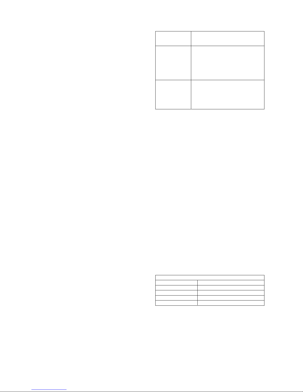
Steady green
System okay. The power source and
wire feeder are communicating
normally.
Blinking green
Occurs during a reset and indicates
the power source is identifying each
component in the system. This is
normal for the first 60 seconds after
power-up, or if the system
configuration is changed during
operation.
Alternating
green and red
Non-recoverable system fault. If the
power source or wire feeder status
LED is flashing any combination of
red and green, errors are present in
the system. Read the error code
before the machine is turned off.
RECOMMENDED PROCESSES AND
EQUIPMENT
RECOMMENDED PROCESSES
The POWER WAVE® STT® MODULE (CE) is
recommended for all process supported by the host
power source including, but not limited to SMAW,
GMAW, GMAW-P, GMAW-STT.
PROCESS LIMITATIONS
The POWER WAVE® STT® MODULE (CE) is
unaffected by the voltage at the load, and therefore
processes are only limited by the current and duty cycle
ratings listed in the specifications for the product. The
POWER WAVE® STT® MODULE (CE) is designed to
protect itself from the excessive transient voltages
associated with highly inductive weld circuits. These high
inductance circuits may result in unsatisfactory
performance, but will not damage the module.
Although the STT Module can be configured to support
negative electrode polarity processes, such as
Innershield, the STT process must be configured to use
positive electrode polarity.
EQUIPMENT LIMITATIONS
The POWER WAVE® STT® MODULE (CE) is intended
for use with compatible medium range “S” – series
POWER WAVE® power sources such as the S350.
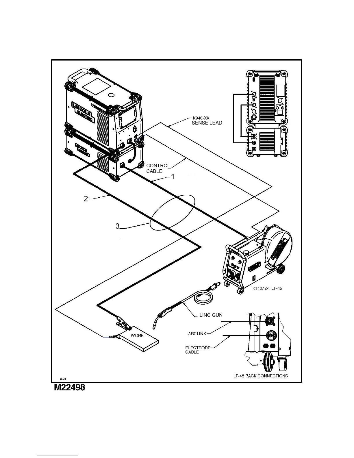
COMMON EQUIPMENT PACKAGES
Basic Package (CE)
K2921-1 STT® Module (CE)
K2823-2 Power Wave® S350 (CE)
K14072-1 LF-45
K10349-PG(W)-XX Interconnecting cable package
K3168-1 Power Wave S500 CE