Imagine DTD-5230 User manual

Delivering the Moment
Installaon and Operaon Manual
Edion B
175-000025-00
DTD-5230, DTD-5231, and
DTD-5233
Digital Time/Date Display Clocks

Publicaon Informaon
© 2014 Imagine Communicaons Corp. Proprietary and Condenal.
Imagine Communicaons considers this document and its contents to be proprietary and condenal. Except for
making a reasonable number of copies for your own internal use, you may not reproduce this publicaon, or any part
thereof, in any form, by any method, for any purpose, or in any language other than English without the wrien consent
of Imagine Communicaons. All others uses are illegal.
This publicaon is designed to assist in the use of the product as it exists on the date of publicaon of this manual, and
may not reect the product at the current me or an unknown me in the future. This publicaon does not in any way
warrant descripon accuracy or guarantee the use for the product to which it refers. Imagine Communicaons reserves
the right, without noce to make such changes in equipment, design, specicaons, components, or documentaon as
progress may warrant to improve the performance of the product.
Trademarks
6800+™, ADC™, CCS Navigator™, Channel ONE™, ChannelView™, ClipSync™, Delay™, D Series™, D Series DSX™, Deliver
the Moment™, Delivering the Moment™, FAME™, Farad™, G8™, G Scribe™, HView™, IconMaster™, IconLogo™, IconSta-
on™, IconKey™, InfoCaster™, InfoCaster Creator™, InfoCaster Manager™, InfoCaster Player™, InstantOnline™, Invenio®,
Live Update™, mCAPTURE™, Magellan™, Magellan CCS Navigator™, Magellan Q SEE™, MulService SDN™, NetPlus™,
NetVX™, NewsForce™, Nexio® G8™, Nexio AMP® ChannelView™, Nexio® Channel ONE™, Nexio® ClipSync™, Nexio®
Delay™, Nexio® Digital Turnaround Processor™, Nexio® Farad™, Nexio® G Scribe™, Nexio® IconKey™, Nexio® IconLogo™,
Nexio® IconMaster™, Nexio® IconStaon™, Nexio® InfoCaster™, Nexio® InfoCaster Creator™, Nexio® InfoCaster Manag-
er™, Nexio® InfoCaster Player™, Nexio® InfoCaster Trac™, Nexio® InstantOnline™, Nexio® mCAPTURE™, Nexio® News-
Force™, Nexio® NXIQ™, Nexio® Playlist™, Nexio® Remote™, Nexio®RTX Net™, Nexio® TitleMoon™, Nexio® TitleOne™,
Nexio® Velocity ESX™, Nexio® Velocity PRX™, Nexio® Velocity XNG™, Nexio® Volt™, OPTO+™, Panacea™, Planum™,
Playlist™, Predator II GRF™, Predator II GX™, Punctuate™, Remote™, RTX Net™, QuiC™, Q SEE™, SD STAR™, Selenio™,
Selenio 6800+™, SelenioNext™, Selenio X50™, Selenio X85™, Selenio X100™, TitleMoon™, TitleOne™, Velocity ESX™,
Velocity PRX™, Velocity XNG™, Versio™, Videotek® SD STAR™, X50™, and X85™ are trademarks of Imagine Communica-
ons or its subsidiaries.
Altude Express®, Connectus®, Enabling PersonalizedTV®, ICE® Broadcast System, ICE Illustrate®, ICE Q® algorithms, ICE-
PAC®, Imagine ICE®, Inscriber®, Inscriber® Connectus®, Invenio®, NEO®, Nexio®, Nexio AMP®, PersonalizedTV®, Router-
Works®, Videotek®, Videotek® ASI STAR®, Videotek® GEN STAR®, and Videotek® HD STAR® are registered trademarks of
Imagine Communicaons or its subsidiaries.
Microso® and Windows® are registered trademarks of Microso Corporaon. HD BNC is a trademark of Amphenol
Corporaon. Some products are manufactured under license from Dolby Laboratories. Dolby and the double D symbol
are registered trademarks of Dolby Laboratories. DTS Neural audio products are manufactured under license from DTS
Licensing Limited. DTS and the Symbol are registered trademarks & the DTS Logos are trademarks of DTS, Inc. © 2008
2010 DTS, Inc. All other trademarks and trade names are the property of their respecve companies.
Contact Informaon
Imagine Communicaons has oce locaons around the world. For locaons and contact informaon see:
hp://www.imaginecommunicaons.com/contact us/
Support Contact Informaon
For support contact informaon see:
▪Support Contacts: hp://www.imaginecommunicaons.com/services/technical support/
▪eCustomer Portal: hp://support.imaginecommunicaons.com
© 2014 Imagine Communicaons Corp. Proprietary and Condenal

Edition B
October 2006
DTD-5230,
DTD-5231, and
DTD-5233
Digital Time/Date Display Clocks
Installation and Operation Manual


DTD-5230, DTD-5231, and DTD-5233 Installation and Operation Manual iii
Contents
Preface
Manual Information .................................................................................v
Purpose ..............................................................................................v
Audience ...........................................................................................v
Revision History ...............................................................................v
Writing Conventions ....................................................................... vi
Obtaining Documents ..................................................................... vi
Unpacking/Shipping Information ......................................................... vii
Unpacking a Product ...................................................................... vii
Product Servicing ........................................................................... vii
Returning a Product ....................................................................... vii
Restriction on Hazardous Substances (RoHS) Compliance ................ viii
Waste from Electrical and Electronic Equipment (WEEE) Compliance ix
Safety .......................................................................................................x
Safety Terms and Symbols in this Manual .......................................x
Chapter 1: Introducing the DTD-523X Clock Series
Overview ..................................................................................................1
Available Models ..............................................................................2
Chapter 2: Installing the DTD-523x
Overview ..................................................................................................3
Installation Requirements ........................................................................4
Rack Mounting .................................................................................4
Cooling ..............................................................................................4
Rear Panel Installation .............................................................................5
Input Switch Functions .....................................................................5
Power Supply ...........................................................................................5

iv DTD-5230, DTD-5231, and DTD-5233 Installation and Operation Manual
Contents
Chapter 3: Operation
Overview ................................................................................................. 7
Setting the Control Mode ........................................................................ 8
Clock Mode ...................................................................................... 9
Timecode Reader Mode ................................................................. 10
Secondary Reference Mode ........................................................... 10
Auxiliary Offset ............................................................................. 11
Date Display ................................................................................... 12
Timecode Generator Mode ............................................................ 12
Brightness Adjustment ................................................................... 13
Clock Setting ......................................................................................... 14
Manual Time Setting ...................................................................... 14
Local Offset Programming ............................................................. 15
Chapter 4: Specifications
Overview ............................................................................................... 17
Input Specifications ........................................................................ 18
Output Specifications ..................................................................... 18
Electrical Specifications ................................................................. 18
Time Base Specifications ............................................................... 19
Control Specifications .................................................................... 19
Mechanical Specifications ............................................................. 20
Appendix A: Servicing Instructions
Overview ............................................................................................... 21
Fuse Replacement ................................................................................. 22
Replacement Procedure .................................................................. 22
Battery Replacement ............................................................................. 23
Battery Use Warnings .................................................................... 23
Replacement Procedure .................................................................. 24
Voltage Selection .................................................................................. 25
Index
Keywords .............................................................................................. 27

DTD-5230, DTD-5231, and DTD-5233 Installation and Operation Manual v
Preface
Manual Information
Purpose
This manual details the features, installation, operation, maintenance,
and specifications for DTD-5230, DTD-5231, and DTD-5233 Digital
Time/Date Display Clocks.
Audience
This manual is written for engineers, technicians, and operators
responsible for installation, setup, maintenance, and/or operation of
DTD-5230, DTD-5231, and DTD-5233 Digital Time/Date Display
Clocks.
Revision History
Table P-1. Revision History of Manual
Edition Date Comments
A March 2002 Full release
B October 2006 Manual reformatted and updated

vi DTD-5230, DTD-5231, and DTD-5233 Installation and Operation Manual
Preface
Writing Conventions
To enhance your understanding, the authors of this manual have
adhered to the following text conventions:
Obtaining Documents
Product support documents can be viewed or downloaded from our
Web site at www.broadcast.harris.com/leitch (go to Support>
Documentation). Alternatively, contact your Customer Service
representative to request a document.
Table P-2. Writing Conventions
Term or
Convention Description
Bold Indicates dialog boxes, property sheets, fields, buttons,
check boxes, list boxes, combo boxes, menus,
submenus, windows, lists, and selection names
Italics Indicates E-mail addresses, the names of books or
publications, and the first instances of new terms and
specialized words that need emphasis
CAPS Indicates a specific key on the keyboard, such as
ENTER, TAB, CTRL, ALT, or DELETE
Code Indicates variables or command-line entries, such as a
DOS entry or something you type into a field
> Indicates the direction of navigation through a hierarchy
of menus and windows
hyperlink Indicates a jump to another location within the
electronic document or elsewhere
Internet address Indicates a jump to a Web site or URL
Note Indicates important information that helps to avoid and
troubleshoot problems

DTD-5230, DTD-5231, and DTD-5233 Installation and Operation Manual vii
Preface
Unpacking/Shipping Information
Unpacking a Product
This product was carefully inspected, tested, and calibrated before
shipment to ensure years of stable and trouble-free service.
1. Check equipment for any visible damage that may have occurred
during transit.
2. Confirm that you have received all items listed on the packing list.
3. Contact your dealer if any item on the packing list is missing.
4. Contact the carrier if any item is damaged.
5. Remove all packaging material from the product and its associated
components before you install the unit.
Keep at least one set of original packaging, in the event that you need to
return a product for servicing.
Product Servicing
DTD-5230, DTD-5231, and DTD-5233 Digital Time/Date Display
Clocks are not designed for field servicing. All upgrades, modifications,
or repairs require you to return the product to the Customer Service
center.
Returning a Product
In the unlikely event that your product fails to operate properly, please
contact Customer Service to obtain a Return Authorization (RA)
number, then send the unit back for servicing.
Keep at least one set of original packaging in the event that a product
needs to be returned for service. If the original package is not available,
you can supply your own packaging as long as it meets the following
criteria:
• The packaging must be able to withstand the product’s weight.
• The product must be held rigid within the packaging.
• There must be at least 2 in. (5 cm) of space between the product and
the container.
• The corners of the product must be protected.

viii DTD-5230, DTD-5231, and DTD-5233 Installation and Operation Manual
Preface
Ship products back to us for servicing prepaid and, if possible, in the
original packaging material. If the product is still within the warranty
period, we will return the product prepaid after servicing.
Restriction on Hazardous Substances (RoHS)
Compliance
Directive 2002/95/EC—commonly known as the European Union (EU)
Restriction on Hazardous Substances (RoHS)—sets limits on the use of
certain substances found in electrical and electronic equipment. The
intent of this legislation is to reduce the amount of hazardous chemicals
that may leach out of landfill sites or otherwise contaminate the
environment during end-of-life recycling. The Directive takes effect on
July 1, 2006, and it refers to the following hazardous substances:
• Lead (Pb)
• Mercury (Hg)
• Cadmium (Cd)
• Hexavalent Chromium (Cr-V1)
• Polybrominated Biphenyls (PBB)
• Polybrominated Diphenyl Ethers (PBDE)
According to this EU Directive, all products sold in the European Union
will be fully RoHS-compliant and “lead-free.” (See our Web site,
www.broadcast.harris.com/leitch, for more information on dates and
deadlines for compliance.) Spare parts supplied for the repair and
upgrade of equipment sold before July 1, 2006 are exempt from the
legislation. Equipment that complies with the EU directive will be
marked with a RoHS-compliant emblem, as shown in Figure P-1.
Figure P-1. RoHS Compliance Emblem

DTD-5230, DTD-5231, and DTD-5233 Installation and Operation Manual ix
Preface
Waste from Electrical and Electronic
Equipment (WEEE) Compliance
The European Union (EU) Directive 2002/96/EC on Waste from
Electrical and Electronic Equipment (WEEE) deals with the collection,
treatment, recovery, and recycling of electrical and electronic waste
products. The objective of the WEEE Directive is to assign the
responsibility for the disposal of associated hazardous waste to either
the producers or users of these products. Effective August 13, 2005,
producers or users will be required to recycle electrical and electronic
equipment at end of its useful life, and may not dispose of the
equipment in landfills or by using other unapproved methods. (Some
EU member states may have different deadlines.)
In accordance with this EU Directive, companies selling electric or
electronic devices in the EU will affix labels indicating that such
products must be properly recycled. (See our Web site,
www.broadcast.harris.com/leitch, for more information on dates and
deadlines for compliance.) Contact your local sales representative for
information on returning these products for recycling. Equipment that
complies with the EU directive will be marked with a WEEE-compliant
emblem, as shown in Figure P-2.
Figure P-2. WEEE Compliance Emblem

x DTD-5230, DTD-5231, and DTD-5233 Installation and Operation Manual
Preface
Safety
Carefully review all safety precautions to avoid injury and prevent
damage to this product or any products connected to it. If this product is
rack-mountable, it should be mounted in an appropriate rack using the
rack-mounting positions and rear support guides provided. It is
recommended that each frame be connected to a separate electrical
circuit for protection against circuit overloading. If this product relies
on forced air cooling, it is recommended that all obstructions to the air
flow be removed prior to mounting the frame in the rack.
If this product has a provision for external earth grounding, it is
recommended that the frame be grounded to earth via the protective
earth ground on the rear panel.
IMPORTANT! Only qualified personnel should perform service
procedures.
Safety Terms and Symbols in this Manual
WARNING
Statements identifying conditions or
practices that may result in personal injury
or loss of life. High voltage is present.
CAUTION
Statements identifying conditions or
practices that can result in damage to the
equipment or other property.

DTD-5230, DTD-5231, and DTD-5233 Installation and Operation Manual 1
Chapter 1
Introducing the DTD-523XClock Series
Overview
The DTD-523x series of digital time/date display clocks (including the
DTD-5230, DTD-5231, and DTD-5233) replaces the following clocks:
•DTD-5200
•DTD-5210
•DTD-5203
Note
Except where noted, the term “DTD-523x” is used in this manual to
refer to the DTD-5230, DTD-5231, and DTD-5233 digital time/date
display clocks.
The DTD-523x series are digitally controlled, self-setting clocks. They
operate in one of two modes: Stand-alone mode via power line
frequency or internal crystal, or with an SMPTE or EBU serial timecode
input as either a clock or a timecode reader.
When provided with an SMPTE or EBU timecode source, the
DTD-523x series of clocks are instantly self-setting. In the event of a
power failure, the DTD-523x clocks maintain the correct time internally
via a battery-backed timekeeping memory. If power is restored without
timecode, the clocks will self-set to the correct time as maintained by
the battery backup, and then continue to operate on internal crystal or
power-line time base.

2 DTD-5230, DTD-5231, and DTD-5233 Installation and Operation Manual
Chapter 1: Introducing the DTD-523X Clock Series
DTD-523x clocks automatically decode either SMPTE or EBU
timecode inputs. Additionally, these clocks function as timecode
generators when operated from their internal crystals. Either SMPTE or
EBU timecode can be generated and used to drive other clocks.
When driven from the MTG-3901 Master Time Generator or
CSD-3901/3902 Clock System Driver, DTD-523x clocks are
compatible with a user-defined auxiliary time offset and date. Some
abilities are as follows:
•Local offset can also be programmed up to 23:59:59.
•Time display can be either 12- or 24-hour format, and can display
HH:MM:SS or MM:SS.FF.
•Dates can be displayed as month:day:year (MM:DD:YY) or
day:month:year (DD:MM:YY).
In the event of a timecode input failure, the colon LEDs flash at the rate
of twice per second. DTD-523x clocks then automatically switch to the
user-selected secondary time base, either power line frequency or
internal crystal. (The power line frequency is automatically determined
during power-up.)
If timecode operation is not required, DTD-523x clocks may be set to
use the secondary time base permanently, and the colon LEDs will not
flash.
If operated as a timecode reader display, DTD-523x clocks continually
track the input code, and then stop when the input fails. The colon
LEDs extinguish when timecode is absent in this mode.
The digital time/date display clocks are available in rack-mount (1 RU)
or desktop versions.
Available Models
The following digital time/date display clock models are available:
•DTD-5230 Digital Time Display (0.8 in./20.3 mm display)
•DTD-5231 Digital Time Display, desktop, time, or date
•DTD-5233 Digital Time Display with dual time or date

DTD-5230, DTD-5231, and DTD-5233 Installation and Operation Manual 3
Chapter 2
Installing the DTD-523x
Overview
This chapter exaplaind the installation process, including unpacking
your equipment, ensuring a safe installation and operating environment,
and connecting a DTD-523x clock.
Note
Except where noted, the term “DTD-523x” is used in this manual to
refer to the DTD-5230, DTD-5231, and DTD-5233 digital time/date
display clocks.
The DTD-523x digital time/date display series of clocks are carefully
inspected, tested, and calibrated before shipment to ensure years of
stable and trouble-free service. Please check the equipment for any
visible damage, which may have been caused during transit.
The following topics are found in this chapter:
•“Installation Requirements” on page 4
•“Rear Panel Installation” on page 5
•“Power Supply” on page 5

4 DTD-5230, DTD-5231, and DTD-5233 Installation and Operation Manual
Chapter 2: Installing the DTD-523x
Installation Requirements
Rack Mounting
The DTD-5230 and DTD-5233 require a standard 1RU rack space.
Dimensions for these rack-mounted clocks are as follows:
Note
The DTD-5231 is a desktop model and does not require rack.
Cooling
The equipment is designed to operate in an ambient temperature range
of 0° to +50° C. No special cooling arrangements are necessary, but
care should be taken to prevent excessive ambient heat rise in closed,
unventilated equipment racks.
Front Panel
Height 1.75 in. (4.4 cm)
Width 19 in. (48.3 cm)
Depth 6 in. (15.2 cm)
PCB Box
Height 1.58 in. (4.01 cm)
Width 8.14 in. (20.68 cm)
Depth 6.5 in. (16.61 cm)

DTD-5230, DTD-5231, and DTD-5233 Installation and Operation Manual 5
Chapter 2: Installing the DTD-523x
Rear Panel Installation
The rear panel has two connectors (see Figure 3-1 on page 3-8).
Depending on the configuration, these connectors either accept or
output serial timecode (SMPTE or EBU). All clocks are shipped
configured for timecode input (slave) operation, unless otherwise
specified when ordering. A label indicates whether the clock is in
Master or Slave configuration.
A standard AC power connector and cord are included.
Input Switch Functions
The DIP switch at the rear of the DTD-523x unit is used to configure
many of the operational parameters of the unit. All switches enable their
corresponding function when in the up position.
See “Setting the Control Mode” on page 8 for details on DIP switch
operation.
Power Supply
The power consumption of the DTD-523x is 6 W at nominally
100-120/200-240 VAC (0.25/0.15 A max.), 50/60 Hz. In order that the
unit operates with maximum stability, it is recommended that the power
be applied 24 hours a day.

6 DTD-5230, DTD-5231, and DTD-5233 Installation and Operation Manual
Chapter 2: Installing the DTD-523x

DTD-5230, DTD-5231, and DTD-5233 Installation and Operation Manual 7
Chapter 3
Operation
Overview
This chapter explains how to operate the DTD-523x series of digital
time/date display clocks.
The following topics are found in this chapter:
•“Setting the Control Mode” on page 8
•“Clock Setting” on page 14
Note
Except where noted, the term “DTD-523x” is used in this manual to
refer to the DTD-5230, DTD-5231, and DTD-5233 digital time/date
display clocks.
8 DTD-5230, DTD-5231, and DTD-5233 Installation and Operation Manual
Chapter 3: Operation
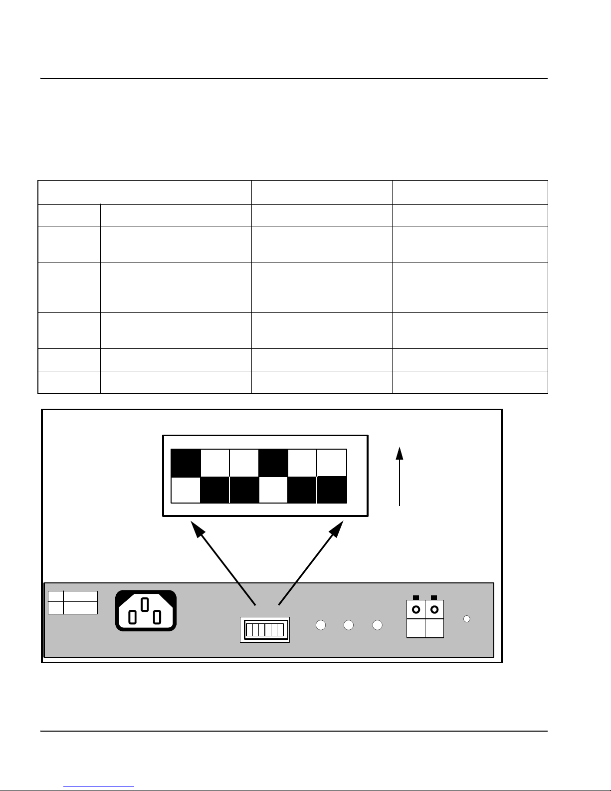
Setting the Control Mode
DTD-523x control modes are selected with rear panel DIP switches.
These switches are described in the table below. Each mode is described
in the pages that follow.
Figure 3-1. DTD-523x DIP Switches
Switch Closed Position (Up) Opened Position (Down)
SW1-1 Display format 12-hour (HH:MM:SS) 24-hour (HH:SS:FF)
SW1-2 Normal and secondary
reference
Normal Run on secondary
(Date if code present)
SW1-3 Auxiliary offset Normal Use auxiliary offset
(MTG-3901, CSD-3901/3902
required)
SW1-4 Secondary reference Internal—Secondary
reference
Line
SW1-5 Timecode output format SMPTE—Output format EBU
SW1-6 Clock mode Clock Timecode
SW1~SW6
RESET MANUAL
INC DEC SET
TIMECODE
GND
TIMECODE
IN/OUT
100-120
200-240
DTD-523x Rear Panel
Detail of DIP Switches
1-1 1-2 1-3 1-4 1-5 1-6
Closed
Opened
100-120 VAC/200-240 VAC
50/60 Hz
0.25/0.15 A max.
This manual suits for next models
2
Table of contents
Other Imagine Clock manuals


