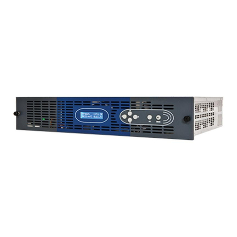
Imagine Videotek VTM-2400 User manual

Delivering the Moment
Videotek™ VTM-2400
Multi-Format HD and SD-SDI Monitor
Edition C
Item # 061782
Installation and Operation
Manual

Publication Information
© 2014 Imagine Communications Corp. Proprietary and Confidential.
Imagine Communications considers this document and its contents to be proprietary and confidential.
Except for making a reasonable number of copies for your own internal use, you may not reproduce
this publication, or any part thereof, in any form, by any method, for any purpose, or in any language
other than English without the written consent of Imagine Communications. All others uses are illegal.
This publication is designed to assist in the use of the product as it exists on the date of publication of
this manual, and may not reflect the product at the current time or an unknown time in the future. This
publication does not in any way warrant description accuracy or guarantee the use for the product to
which it refers. Imagine Communications reserves the right, without notice to make such changes in
equipment, design, specifications, components, or documentation as progress may warrant to improve
the performance of the product.
Trademarks
Videotek® VTM is a trademark of Imagine Communications or its subsidiaries.
Microsoft® and Windows® are registered trademarks of Microsoft Corporation. All other trademarks
and trade names are the property of their respective companies.
Contact Information
Imagine Communications has office locations around the world. For locations and contact information
see: http://www.imaginecommunications.com/contact-us/
Support Contact Information
For support contact information see:
Support Contacts: http://www.imaginecommunications.com/services/technical-support/
eCustomer Portal: http://support.imaginecommunications.com

VTM-2400 Installation and Operation Handbook iii
Operator’s Safety Summary
WARNING: These instructions are for use by qualified personnel only. To reduce
the risk of electric shock, do not perform this installation or any servicing unless you
are qualified to do so. Refer all servicing to qualified service personnel.
Ensuring Safety
The unit should not be exposed to dripping or splashing, and no objects filled with liquids,
such as vases, shall be placed on the unit.
When the unit is to be permanently cabled, connect the protective ground conductor
before making any other connections.
Operate built-in units only when they are properly fitted into the system.
For permanently cabled units without built-in fuses, automatic switches, or similar
protective facilities, the AC supply line must be fitted with fuses rated to the units.
Before switching on the unit, ensure that the operating voltage set at the unit matches
the line voltage, if appropriate. If a different operating voltage is to be set, use a fuse with
the appropriate rating. Refer to the Installation Instructions.
Units of Protection Class I with an AC supply cable and plug that can be disconnected
must be operated only from a power socket with protective ground contact:
−Do not use an extension cable—it can render the protective ground connection
ineffective.
−Do not intentionally interrupt the protective ground conductor.
−Do not break the protective ground conductor inside or outside the unit or loosen the
protective ground connection; such actions can cause the unit to become electrically
hazardous.
Before opening the unit, isolate it from the AC supply, and then ensure that
−Adjustments, part replacements, maintenance, and repairs are carried out by
qualified personnel only.
−Safety regulations and rules are observed to prevent accidents.
−Only original parts are used to replace parts relevant to safety (for example, the
power on/off switches, power transformers, and fuses).
Replaceable fuses can be hazardous when live. Before replacing a fuse, disconnect the AC
power source.

Operator’s Safety Summary
iv VTM-2400 Installation and Operation Handbook
Use caution when cleaning the equipment; isopropyl alcohol or similar solvents can
damage or remove the labels.
Observe any additional safety instructions specified in this manual.
Important Safety Instructions
Read these instructions.
Keep these instructions.
Heed all warnings.
Follow all instructions.
Do not use this apparatus near water.
Clean only with dry cloth.
Do not block any ventilation openings. Install in accordance with the manufacturer’s
instructions.
Do not install near any heat sources such as radiators, heat registers, stoves, or other
apparatus (including amplifiers) that produce heat.
Do not defeat the safety purpose of the polarized or grounding-type plug. A polarized
plug has two blades with one wider than the other. A grounding type plug has two
blades and a third grounding prong. The wide blade or the third prong is provided for
your safety. If the provided plug does not fit into your outlet, consult an electrician for
replacement of the obsolete outlet.
Protect the power cord from being walked on or pinched particularly at plugs,
convenience receptacles, and the point where they exit from the apparatus.
Only use attachments/accessories specified by the manufacturer.
Unplug this apparatus during lightning storms or when unused for long periods of
time.
Refer all servicing to qualified service personnel. Servicing is required when the
apparatus has been damaged in any way, such as power-supply cord or plug is
damaged, liquid has been spilled or objects have fallen into the apparatus, the
apparatus has been exposed to rain or moisture, does not operate normally, or has
been dropped.
The device’s IEC power connector shall remain readily accessible.
WARNING: To reduce the risk of fire or electric shock, do not expose this
apparatus to rain or moisture.

Operator’s Safety Summary
VTM-2400 Installation and Operation Handbook v
Explanation of Symbols
These symbols may appear on Imagine Communications equipment:
Certification Labels and Symbol Locations
On Imagine Communications equipment, certification labels and symbols are located on the
back panel, rear chassis sides, or bottom rear of the chassis. On smaller space-restricted units,
most labels and symbols can be found on the bottom rear of the chassis.

Directives and Compliances
vi VTM-2400 Installation and Operation Handbook
Directives and Compliances
This section provides information concerning Imagine Communications compliance with EU
Directive 2002/95/EC and EU Directive 2002/96/EC.
Restriction on Hazardous Substances (RoHS) Directive 2002/95/EC
Hazardous Substances (RoHS)—sets limits on the use of certain substances found in electrical
and electronic equipment. The intent of this legislation is to reduce the amount of hazardous
chemicals that may leach out of landfill sites or otherwise contaminate the environment
during end-of-life recycling. The Directive, which took effect on July 1, 2006, refers to the
following hazardous substances:
Lead (Pb)
Mercury (Hg)
Cadmium (Cd)
Hexavalent Chromium (Cr-V1)
Polybrominated Biphenyls (PBB)
Polybrominated Diphenyl Ethers (PBDE)
In accordance with this EU Directive, all Imagine Communications products sold in the
European Union will be fully RoHS-compliant and “lead-free.” (See the Imagine
Communications Premier website for more information on dates and deadlines for
compliance.) Spare parts supplied for the repair and upgrade of equipment sold before July 1,
2006 are exempt from the legislation. Imagine Communications equipment that complies
with the EU directive will be marked with a RoHS-compliant symbol, as shown in Figure 1.
Figure 1. RoHS Compliance Symbol
Waste from Electrical and Electronic Equipment (WEEE) Directive
2002/96/EC
The European Union (EU) Directive 2002/96/EC on Waste from Electrical and Electronic
Equipment (WEEE) deals with the collection, treatment, recovery, and recycling of electrical
and electronic waste products. The objective of the WEEE Directive is to assign the
responsibility for the disposal of associated hazardous waste to either the producers or users
of these products. As of August 13, 2005, producers or users are required to recycle electrical
and electronic equipment at end of its useful life, and must not dispose of the equipment in

VTM-2400 Installation and Operation Handbook vii
landfills or by using other unapproved methods. (Some EU member states may have different
deadlines.)
In accordance with this EU Directive, Imagine Communications and other companies selling
electric or electronic devices in the EU will affix labels indicating that such products must be
properly recycled.
(See the Imagine Communications Premier website for more information on dates and
deadlines for compliance.) Contact your local Imagine Communications sales representative
for information on returning these products for recycling. Imagine Communications
equipment that complies with the EU directive will be marked with a WEEE-compliant symbol,
as shown in Figure 2.
Figure 2. WEEE Compliance Symbol

VTM-2400 Installation and Operation Handbook viii
Contents
Operator’s Safety Summary ....................................................................................iii
Ensuring Safety ...........................................................................................................................iii
Important Safety Instructions.......................................................................................................iv
Explanation of Symbols................................................................................................................v
Certification Labels and Symbol Locations ..................................................................................v
Directives and Compliances....................................................................................vi
Restriction on Hazardous Substances (RoHS) Directive 2002/95/EC........................................vi
Waste from Electrical and Electronic Equipment (WEEE) Directive 2002/96/EC.......................vi
Section 1 ♦Introduction...........................................................................................1
Video Standards Supported .........................................................................................................2
Service and Support.....................................................................................................................4
Section 2 ♦Installation.............................................................................................5
Inspecting the Shipment...............................................................................................................5
Rack Mounting the VTM-2400......................................................................................................6
Connecting the VTM-2400...................................................................................................7
Ethernet Setup.....................................................................................................................7
Configuring the VTM/TVM Series with the RCU-2400 Remote Control............................11
Section 3 ♦General Operation...............................................................................12
Terms..........................................................................................................................................12
Introduction to Operating the VTM-2400....................................................................................12
Types of Controls........................................................................................................................15
Selecting a Pane.........................................................................................................................16
Full-Screen Display Selection............................................................................................16
Selecting a Video Input...............................................................................................................16

Contents
VTM-2400 Installation and Operation Handbook ix
Powering Down from the Front Panel........................................................................................ 16
Navigating the Pane Setup Menu.............................................................................................. 16
Reference.......................................................................................................................... 17
Pane Overview .......................................................................................................................... 17
Main Title Bar.................................................................................................................... 18
Icons ............................................................................................................................. 19
Status Bar ......................................................................................................................... 19
The Waveform Display .............................................................................................................. 19
Waveform Front Panel Selections .................................................................................... 23
Moving the Waveform using the Setup Knobs ............................................................. 23
Sweep Button ............................................................................................................... 23
MAG Button .................................................................................................................. 24
Gain Button................................................................................................................... 24
Zoom Button ................................................................................................................. 25
Placing the Waveform Display in Line Select Mode..................................................... 25
Waveform Pane Menu Selections..................................................................................... 26
Filter Selection.............................................................................................................. 28
Parade and Overlay Selections.................................................................................... 28
Format .......................................................................................................................... 28
Blanking........................................................................................................................ 28
Component Sequence.................................................................................................. 29
Center Waveform.......................................................................................................... 29
Waveform Setup........................................................................................................... 29
Utilizing the Vector Display........................................................................................................ 29
Gain Button....................................................................................................................... 31
Zoom Button ................................................................................................................. 32
Placing the Vector Display in Line Select Mode.......................................................... 33
Vector Pane Menu Selections........................................................................................... 33

Contents
x VTM-2400 Installation and Operation Handbook
Standard........................................................................................................................34
Vector Position...............................................................................................................34
Center Vector.................................................................................................................34
Vector Setup..................................................................................................................34
Picture Display............................................................................................................................34
Alarm Status Display ..................................................................................................................35
Audio Display..............................................................................................................................37
Audio Scales......................................................................................................................37
Vertical Audio Displays..................................................................................................38
Expanding the Audio Display.............................................................................................41
Presets........................................................................................................................................41
Storing Presets ..................................................................................................................41
Recalling Presets...............................................................................................................42
Preset 4 (Factory Preset)...................................................................................................42
Section 4 ♦Global Setup Menu Functions............................................................ 43
Navigating the Setup Menu........................................................................................................43
Setup Menu and Alarm Tables...................................................................................................43
Video Format Menu ...........................................................................................................56
Video A and B Configure...............................................................................................56
Waveform Setup Menu......................................................................................................56
Digital Waveform Graticule............................................................................................56
Waveform Intensity........................................................................................................56
Waveform Contrast........................................................................................................56
Persistence....................................................................................................................56
Attack.............................................................................................................................56
Vector Setup Menu ............................................................................................................57
SD I/Q Lines ..................................................................................................................57
Vector Intensity..............................................................................................................57
Vector Contrast..............................................................................................................57

Contents
VTM-2400 Installation and Operation Handbook xi
Persistence................................................................................................................... 57
Attack............................................................................................................................ 57
Audio Setup Menu ............................................................................................................ 57
Configure Inputs ........................................................................................................... 57
Meter Setup .................................................................................................................. 58
AES Validity Bit............................................................................................................. 60
Output Preferences....................................................................................................... 60
Display Setup.................................................................................................................... 60
Display Colors............................................................................................................... 61
Graticule Intensity......................................................................................................... 61
Monitor.......................................................................................................................... 61
Time Code.................................................................................................................... 62
Communications Setup..................................................................................................... 62
RCU Port ...................................................................................................................... 62
IP Configuration............................................................................................................ 62
GPI Output Function..................................................................................................... 63
Unit ID........................................................................................................................... 64
System Setup Menu.......................................................................................................... 64
Panel and Preset Lockout ............................................................................................ 64
Set Time ....................................................................................................................... 67
Time Code Input ........................................................................................................... 67
About................................................................................................................................. 68
Section 5 ♦Alarm Descriptions..............................................................................71
Setting Alarms ........................................................................................................................... 71
Audio Alarms ............................................................................................................................. 71
Peak Audio........................................................................................................................ 71
Loss of Sound................................................................................................................... 71
Video Alarms Digital Descriptions ............................................................................................. 71

Contents
xii VTM-2400 Installation and Operation Handbook
EDH....................................................................................................................................71
CRC HD.............................................................................................................................72
Loss of Carrier ...................................................................................................................72
Digital Gamut .....................................................................................................................72
RGB Upper/Lower .........................................................................................................72
Section 6 ♦Troubleshooting..................................................................................73
Cold Starting the VTM-2400.......................................................................................................73
Cold Start...........................................................................................................................73
Warm Start.........................................................................................................................74
Cold Start after VFlash.......................................................................................................74
Updating with VFlash..................................................................................................................74
Problems, Causes, and Solutions ..............................................................................................74
Appendix A ♦Specifications..................................................................................77
Video Specifications ...................................................................................................................77
Audio Specifications ...................................................................................................................77
Control Specifications.................................................................................................................79
Display Specifications.................................................................................................................79
Time Code Specifications...........................................................................................................79
Magnification Specifications.......................................................................................................80
VFlash Specifications .................................................................................................................81
Remote Control Specifications ...................................................................................................81
Power Requirements..................................................................................................................81
Mechanical Specifications ..........................................................................................................81
Environmental Specifications .....................................................................................................81
Standard Accessories.................................................................................................................82
Options .......................................................................................................................................82

Contents
VTM-2400 Installation and Operation Handbook xiii
Appendix B ♦Pinouts.............................................................................................83
Appendix C ♦RCU-2400 Remote Control Unit......................................................88
Installing the RCU-2400............................................................................................................. 88
Operating the RCU-2400........................................................................................................... 90
Troubleshooting......................................................................................................................... 90
Specifications............................................................................................................................. 91
Power Requirements (External Power Supply)......................................................................... 91
Mechanical Specifications ......................................................................................................... 91
Environmental Specifications .................................................................................................... 91
Standard Accessories................................................................................................................ 92
Pinouts....................................................................................................................................... 93
Appendix D ♦Open Source Software Copyright Information..............................95
FreeType License...................................................................................................................... 95
LibJPEG License ....................................................................................................................... 95
CMU/UCD Copyright Notice...................................................................................................... 95
Networks Associates Technology, Inc. Copyright Notice (BSD)............................................... 96
Cambridge Broadband Ltd. Copyright Notice (BSD)................................................................. 97
Sun Microsystems, Inc. Copyright Notice (BSD)....................................................................... 98
Sparta, Inc. Copyright Notice (BSD).......................................................................................... 99
Cisco/BUPTNIC Copyright Notice (BSD) ................................................................................ 100
Fabasoft R&D Software GmbH & Co. KG Copyright Notice (BSD)......................................... 101
The GNU v2 License ............................................................................................................... 102
GNU General Public License...................................................................................... 102
Version 2, June 1991.................................................................................................. 102
Preamble .................................................................................................................... 102
GNU General Public License...................................................................................... 103
Terms and Conditions for Copying, Distribution and Modification ............................. 103

Contents
xiv VTM-2400 Installation and Operation Handbook
No Warranty.................................................................................................................106
GNU Lesser Public License......................................................................................................107
GNU Lesser General Public License...........................................................................107
Version 2.1, February 1999.........................................................................................107
Preamble .....................................................................................................................107
GNU Lesser General Public License...........................................................................109
Terms and Conditions for Copying, Distribution and Modification ..............................109
No Warranty.................................................................................................................114
Appendix E ♦Glossary......................................................................................... 115
Index ......................................................................................................................125
List of Figures
Figure 1-1. VTM-2400 Front and Back Panels.............................................................................3
Figure 2-1. Mounting the VTM-2400 in a Rack ............................................................................6
Figure 2-2. VTM-2400 Back Panel Connectors............................................................................7
Figure 2-3. VTM-2400 Dedicated PC Connection........................................................................9
Figure 2-4. VTM-2400 Network PC Connection.........................................................................10
Figure 2-5. Connecting the RCU-2400 Remote Control Panel to Multiple VTM-2400 Units......11
Figure 3-1. VTM-2400 Front Panel* ...........................................................................................12
Figure 3-2. Sample Multi-Display ...............................................................................................14
Figure 3-3. Selecting a Pane......................................................................................................16
Figure 3-4. Sample Quad Diagram.............................................................................................18
Figure 3-5. Full-Screen Display Diagram ...................................................................................18
Figure 3-6. Waveform Display Diagram .....................................................................................20
Figure 3-7. RGB and YCBCRGraticule ......................................................................................22
Figure 3-8. RGB and YCBCRZoom 0 mV Graticule...................................................................22
Figure 3-9. RGB and YCBCRZoom 700 mV Graticule...............................................................22
Figure 3-10. Moving the Waveform............................................................................................23

Contents
VTM-2400 Installation and Operation Handbook xv
Figure 3-11. Establishing the Sweep Scale............................................................................... 24
Figure 3-12. Establishing the Gain ............................................................................................ 25
Figure 3-13. Establishing Line Select........................................................................................ 26
Figure 3-14. Vector Display Diagram ........................................................................................ 29
Figure 3-15. Vector SD with I/Q................................................................................................. 31
Figure 3-16. Vector HD 75% + 100% Graticule......................................................................... 31
Figure 3-17. Establishing the Vector Gain................................................................................. 32
Figure 3-18. Establishing Line Select........................................................................................ 33
Figure 3-19. Picture Display Diagram........................................................................................ 35
Figure 3-20. Alarm Status Display Diagram.............................................................................. 36
Figure 3-21. Two Bar Graph Display with Lissajous Diagram................................................... 39
Figure 3-22. Four Bar Graph with Lissajous Display Diagram .................................................. 40
Figure 4-1. Display Color Selection........................................................................................... 61
Figure 4-2. Enter Password Screen .......................................................................................... 64
Figure 4-3. Enter New Time Screen.......................................................................................... 67
Figure 4-4. About Screen........................................................................................................... 68
Figure B-1. Analog Audio IN/OUT 37-Pin, Male, D-Sub Connector for Audio Option............... 83
Figure B-2. XGA OUT 15-Pin, Female, D-Sub Connector........................................................ 85
Figure B-3. GPI/TALLY Connector............................................................................................ 86
Figure B-4. GPI/TALLY Breakout Board.................................................................................... 86
Figure B-5. Remote RJ-11 Control Connector .......................................................................... 87
Figure B-6. VFlash RJ-45 Connector ........................................................................................ 87
Figure C-1. RCU- 2400 Front and Back Panel Views ............................................................... 88
Figure C-2. Connecting the RCU to Multiple VTM-2400s ......................................................... 89
Figure C-3. RCU-2400 to Main Unit RJ-11 Connector.............................................................. 93
List of Tables
Table 2-1. Parts Required to Rack Mount the VTM-2400 using the DRC-2 ............................... 6
Table 2-2. Description of Back Panel Connectors....................................................................... 7

Contents
xvi VTM-2400 Installation and Operation Handbook
Table 3-1. Front Panel Description.............................................................................................12
Table 3-2. Description of Quad Screen Display.........................................................................14
Table 3-3. Description of Icons...................................................................................................19
Table 3-4. Video Formats and Units of Measure........................................................................19
Table 3-5. Video Formats and Critical Amplitude Limits ............................................................20
Table 3-6. Description of Waveform Display Diagram ...............................................................21
Table 3-7. Waveform (HD-SDI) Menu Structure ........................................................................26
Table 3-8. Waveform (SD-SDI) Menu Structure.........................................................................27
Table 3-9. Description of Vector Display Diagram .....................................................................30
Table 3-10. Vector Pane Menu...................................................................................................33
Table 3-11. Description of Picture Display Diagram...................................................................35
Table 3-12. Description of Alarm Status Display Diagram.........................................................36
Table 3-13. Alarm Status Pane Menu ........................................................................................37
Table 3-14. Description of Two Bar Graph Display with Lissajous Diagram..............................39
Table 3-15. Description of Four Bar Graph with Lissajous Display Diagram .............................40
Table 4-1. Setup Menu Tables...................................................................................................44
Table 4-2. Video Format Menu...................................................................................................44
Table 4-3. Waveform Setup Menu..............................................................................................46
Table 4-4. Vector Setup Menu....................................................................................................47
Table 4-5. Audio Setup Menu.....................................................................................................47
Table 4-6. Audio Alarms Menu...................................................................................................51
Table 4-7. Video Alarms, Digital Menu.......................................................................................52
Table 4-8. Display Setup Menu..................................................................................................53
Table 4-9. Display Colors Menu.................................................................................................54
Table 4-10. Communications Setup Menu.................................................................................54
Table 4-11. System Setup Menu................................................................................................55
Table 4-12. About Menu.............................................................................................................56
Table 4-13. Ballistic Specifications with Attack and Decay........................................................59
Table 5-1. CRC Alarm Error Types ............................................................................................72

Contents
VTM-2400 Installation and Operation Handbook xvii
Table 6-1. VTM-2400: Problems, Causes, and Solutions ......................................................... 74
Table B-1. Pinouts for Analog Audio IN/OUT Connector and Audio Breakout Board................ 83
Table B-2. XGA OUT Connector Pinouts.................................................................................. 85
Table B-3. Pinouts for GPI/TALLY Connector and GPI/TALLY Breakout Board....................... 86
Table B-4. Remote RJ-11 Control Connector Pinouts .............................................................. 87
Table B-5. VFlash RJ-45 Connector Pinouts............................................................................. 87
Table C-1. Description of RCU-2400 Back Panel Connectors.................................................. 88
Table C-2. RCU-2400: Problems, Causes, and Solutions ........................................................ 90
Table C-3. Pinouts for RCU-2400 to Main Unit Connector........................................................ 93


VTM-2400 Installation and Operation Handbook 1
Section 1 ♦Introduction
The VTM-2400 is a multiformat on-screen monitor with waveform monitor, vectorscope,
picture, and alarm status. It is a 19-inch rack mounted unit that accepts HD-SDI and SD-SDI
video signals, and external analog reference video signals. The display presents the image
carried by the selected video input as a real-time, full-motion picture. Front panel user
controls allow for various display and selection modes.
In addition, the VTM-2400 also accepts the audio option VTM-A3-OPT 1, which is the
Advanced Audio Analysis Option with bargraphs and lissajous. With the VTM-A3-OPT 1 up to
four audio channels can be viewed simultaneously. There are two analog stereo inputs, four
AES/EBU inputs, and 16 channels of embedded audio. It also contains analog monitoring
outputs of up to four channels simultaneously.
The VTM-2400 seamlessly integrates into any broadcast, post-production, camera
maintenance, satellite or cable facility, and is the ultimate choice for quality control,
troubleshooting, or compliance checking applications.
*US Patents 6,069,607, 6,532,024, and 6,828,981. UK Patent 2,330,475. Other US and foreign patents pending.
Features include:
Two active inputs
HD-SDI inputs with passive loop-through outputs and auto detection
SD-SDI input capability
Reference input
XGA, High Resolution, output
Three user presets and one factory preset
Compact 1RU configuration
Input standards: SMPTE 259MC-1997, ITU-R BT.601, SMPTE 292M-1998, SMPTE
296M-2001, SMPTE 299M-2004, SMPTE 291M-1998, SMPTE 334M-2000, SMPTE
272M-2004, SMPTE 294M-2001, and SMPTE 276M-1995

Introduction
2 VTM-2400 Installation and Operation Handbook
Video Standards Supported
The VTM-2400 supports the following video standards:
For HD:
1080i/60
1080i/59.94
1080i/50
1080p/30
1080p/29.97
1080p/25
1080p/24
1080p/23.98
1080p/30sF
1080p/29.97sF
1080p/25sF
1080p/24sF
1080p/23.98sF
720p/60
720p/59.94
720p/50
720p/30
720p/29.97
720p/24
720p/23.98
For SD:
525/59.94
625/50
Table of contents
Other Imagine Monitor manuals
