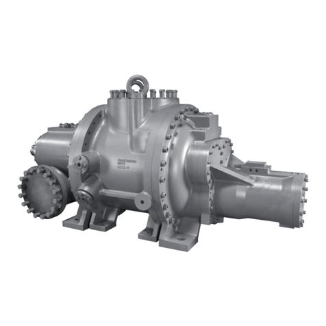
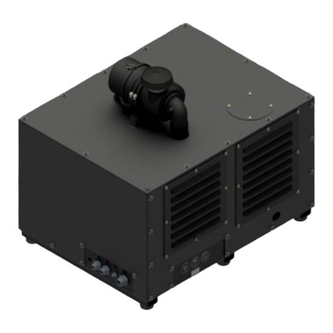
IMC IMCAHB-10 Series User manual

1
IMCAHB-10 Series of Air Compressor
Machinery
INTERNATIONAL MACHINE CONCEPTS WELCOMES YOU TO YOUR NEW
MACHINE
Operation Manual: Date 2015. Version 1. Serial Number

2
CONTENTS
Chapter 1
Machine Description 1.1
Uncrating Instructions 1.2
Installation 1.3
Electrical and Pneumatic connections 1.4
Chapter 2
Compressor dimensions 2.1
Chapter 3
Operation Instruction
The air process 3.1
The process of the lubrication oil 3.2
Safe protection system and warming devices 3.3
Control system 3.4
Operation 3.5
Computer control 3.6
Chapter 4
Malfunctions (Faults) and their rectification
Table of possible faults 4.1
Chapter 5
Maintenance Instructions 5.1
Chapter 6
Electrical Diagrams 6.1

3
Chapter 1
1.1 Machine Description
1. The brief introduction of a oil screw type air compressor
The oil screw type compressor is characterized by reliable operation performance, less
wearing parts, low vibration, low noise and high efficiency. During the compression
course, the compressor continuously injects lubrication oil into a compression chamber
and bearings by means of the pressure difference generated.
The lubrication oil has three main effects as following:
(1) Lubrication effect: the lubrication oil can form oil film between rotors, which avoid the
contact between the rotors and reduce friction.
(2) Sealing effect: the oil film generated by the lubrication oil can have the effect of
sealing the compressed air, which improves the volumetric efficiency of the
compressor.
(3) Cooling effect: as the lubrication oil absorbs a large quantity of compression heat, the
compression course is almost the same as the course of isothermal compression,
which reduces the specific power of the compressor. Moreover, the lubrication oil also
can reduce the noise generated by high frequency compression.
2. The structure of the engine body of the oil screw type air compressor
(1) The basic structure
Company has adopted the oil screw type air compressor which is a two shaft positive
replacement rotary type compressor. An air inlet is opened on the upper air end of
the air end casing, and an air outlet is opened at the lower part of the casing. A pair of
high precision main (male) rotor and sub (female) rotors is horizontally and parallel
installed in the internal part of the casing. The main (male) rotor has five shaped
teeth while the sub (female) rotor has six shaped teeth. The main rotor has relatively
large diameter, and the sub rotor has relatively small diameter. The shaped teeth are
in the helix-shaped and circle around the outer edges of the rotors. The teeth of the
shape teeth and outer edges are intermeshed with each other. The ends of the main
rotor and sub rotor are supported by bearings. Air intake ends have one roller
bearing, and air exhaust ends have two tapered roller bearings which are installed
symmetrically. In total, the engine body of the compressor has two kinds. One kind of
the engine body is a belt driven type engine body, and the other kind of the engine
body is a direct-fastened driven type engine body. The direct-fastened driven type
engine body utilizes one coupling to combine the power source of an electric motor
and the main engine body together and improves the rotary speed of the main rotor
through one group of high precision increasing gears. However, the belt driven type
engine body has no the increasing gears. The belt driven type rotary screw
compressor powers via pulleys through belt drive, which are manufactured according
to rpm speed and proportion to the horse power of the unit.

4
(2) Intermeshing
An electric motor, drives the main rotor through the coupling, or belts. As the two
rotors are intermeshed with each other, the main rotor directly drives the sub rotor
to rotate together. The cooling lubrication oil is directly injected into the intermeshing
part via a nozzle, from the lower part of the casing of the compressor. Oil is mixed
with the air, takes along the heat generated by compression and reaches the cooling
effect. Meanwhile, the cooling lubrication oil forms the oil film, which prevents the
direct metal contact between the rotors and prevents the clearance between the
sealing rotors and between the rotors and the casing. The injected lubrication oil can
also reduce the noise generated by the compression in high speed. Because of the
difference of the air exhaust pressure, all the weight of the injected oil is 5-10 times
larger than that of the air.
3. The compression principles of the screw type compressor
(1) The course of absorbing the air.
An air suction port on the air suction side of the screw type compressor is designed
as the compression chamber can fully absorb the air. However, the screw type
compressor has a suction valve and an internal check valve to prevent air back flow.
The intake valve is regulated from a solenoid valve which opens and closes the
suction valve. When the rotors are rotated, the space of the tooth grooves of the
main rotor and sub rotor is maximized as the rotors are rotated into an open intake
end wall. At that time, the space of the tooth grooves on the rotors is produced
with the free air in the air inlet. Therefore, the air in the tooth groove is totally
taken out when the air is exhausted. After the air is completely exhausted, the
tooth grooves are still under a vacuum state. When the rotors are rotated into the
air inlet, the outside air is absorbed and flows into the tooth grooves of the main
rotor and the sub rotor. When the air is full in the tooth grooves, the air intake side
end surfaces of the rotors are rotated away from the air inlet of the casing, and the
air between the tooth grooves is sealed. The above course is called as the ‘the
course of absorbing the air’.
(2) The course of sealing and conveyance.
When the main rotor and the sub rotor complete air suction, the tooth peaks of the
main rotor and sub rotor and the casing will be sealed together. At that time, the
air is sealed in the tooth groove and eliminates back flow. This course is called ‘the
sealing course’. The two rotors are continuously rotated. The tooth peaks and the
tooth grooves are inosculated with each other at the air suction end. The
inosculating surface is gradually moved toward the air exhaust end. This course is
called as ‘the conveyance course’
(3) The course of compression and injecting oil

5
During the conveyance course, the intermeshing surface is gradually moved toward
the air exhaust end. Namely, the space between the intermeshing surface and the
tooth grooves between the air exhaust ports gradually becomes small. The air in
the tooth grooves is gradually compressed, and the pressure is increased. This
course is called ‘the compression course’. Meanwhile, the lubrication oil is also
injected into the compression chamber to be mixed with the air, because of this
action of the pressure difference when the air is compressed.
(4) The course of the air exhaust:
When the intermeshing end surface of the rotors is rotated and with the air
exhaust ports of the casing (the pressure of the compressed air is the highest at this
time), the compressed air starts being exhausted until the intermeshing surface
between the tooth peaks and the tooth grooves is moved to the air exhaust end
surfaces. At that time, the space between the intermeshing surface between the
two rotors and the tooth grooves, between the air exhaust port of the casing is
zero. Then the course of the air exhaust’ is completed. Meanwhile, the length
between the intermeshing surface of the rotors and the tooth grooves between the
air inlet of the casing reaches the maximum length. However, the course of
absorbing the air is continuing.
(1). The course of absorbing the air; (2). The course of sealing and conveyance;
(3). The course of compression and injecting oil; (4). The course of air exhaust.
1.2 Un-crating Instructions
During un-crating make sure that no physical damage to the outside of the crate has taken
place. Carefully break open the exterior panels to reveal the machine and its working parts.
The machine will be covered in a plastic protective cover. This is to be removed. Make sure
that no parts have been damaged during transport, or fallen off the machine. The machine will
arrive with certain parts dis-assembled. These need to be fitted to the machine to resemble
the photos above the machine. The machine is fixed to the wooden palett by four metal
brackets. Remove these brackets and discard or keep for future use. The doors and covers
have been taped closed for safety reasons, these taped parts can now be opened. Surface rust
can take place due to the excessive sea sir during shipping. This will only be surface rust and a
dry cloth should be used to remove this rust residue. The entire machine has bee shipped with

6
an oil coating on the surface to safeguard the machine from corrosion. This can now be
removed with a very light detergent. The non-stainless steel parts should be re-oiled to
prevent rusting taking place after cleaning. Do not leave the machine wet.
The machine is top-heavy and as such, care should be taken when handling the machine and
removing it from its wooden pallet.
NOTE: DO NOT HANDLE THE MACHINE ON THE FILM BRACKETS OR ROLLERS. These parts are
critically aligned and should they be bent out of position the film may run off.
1.3 Installation
Only a qualified technician should perform the machine installation or a suitably trained
person.
Note: it is dangerous to work on a moving machine and the machine should be off and
isolated before any form of work is performed.
Machine should be placed in a well-ventilated room, free from dust and excessively
corrosive materials.
Inspect compressor prior to any use, check for external damage that may occur during
transit. A forklift may be necessary for unloading your new compressor, please use all
forklift safety measures and require a certified forklift operator, operates the fork lift.
Refer to diagrams below for forklift operation including wood block on forks to prevent
damage.
There should be at least 1,5m space around each side of the machine for convenient
operation and maintenance.
Prepare the power supply 380V or 220V/50HZ. Three/Single Phase and neutral, and
connect to an appropriate earth wire.

7
Pneumatic connections should take place as the designated connection. The air should
not be less than 6Bar while the machine is operational. Air should be free of water and
contaminants.
The machine should be placed on level ground. After installing the machine, check if the
machine is level by Level Instrument. If not, please adjust the four legs.
Check every part of the machine carefully for damage during shipping. Tighten any loose
parts, screws and moving parts.
The selected place should have low relative humidity, less dust, clean air and sound
ventilation.
The surrounding temperature of the selected place must be lower than 45 degrees Celsius
and 113 degrees Fahrenheit. And never lower than 0 Celsius and 33 Fahrenheit.
If installing in a dusty or dirty environment it is recommended to install in a separate
clean and well ventilated room or environment. It is imperative to the overall
performance and longevity of the unit and warranty coverage.
All gearboxes should be checked for sufficient oil.
Check all electrical connections for loose wires.
Make a test of the machines electrical power and confirm the voltage and earth
continuity. All safety connections relative to your own country should be adhered to.
Before operating the machine, please lubricate the following parts: across sealing bearing
and its bearing holes, longitudinal where sealing the parts needs oil.
Piping your compressor
The considerations of the tubing and air pipelines
(A): When the main pipelines are tube, the degree of the inclination of the pipelines should
be 1-2°, which offer advantage for draining the condensed water in the pipelines.
(B) The pressure fall of the tube pipelines must not be 5% greater than the set pressure of
the compressor. Therefore, the relative large designed pipe diameter must be selected
when the tubing is implemented this will avoid large drops in pressure.
(C) Sub-line pipelines must extend out of the top ends of the main pipelines, which do not
allow the condensed water in the pipelines to flow into the working machine or reflow
into the compressor.
(D) The tools needing to be lubricated must be installed with a three-element assembly (an
air water-filtering filter, a pressure regulator and an oil feeder) to maintain the service
life of the tools.
(E) Any lines run from the main line must be smaller in size than the main line. Otherwise,
there is the mixed flow at the adapters, which causes pressure drop.
(F) If there is purification and cushion equipment behind the air compressor, such as an air
storage tank and a dryer. The ideal tubing must be ‘air compressor + the air storage tank
+ coalescing filter + the inlet side of the dryer’ so that the air storage tank can filter out
part of the condensed water. Meanwhile, the air storage tank also has the function of

8
decreasing the air exhaust temperature. The air with relative low temperature and less
moisture content can enter into the dryer again, which can reduce the load of the dryer.
Follow directional arrow at the top of the coalescing filter to ensure proper air flow
direction.
(G) If the use level of the air in the system is very high in a short period of time. One air
storage tank may not be sufficient, and a second tank will be necessary for the high air
demand. .
(H) Limit the use of pipelines and valves as much as possible to reduce the loss of the
pressure.
(I) Closed loop piping system is the proffered piping system. This will allow a shorter
distance for the air to travel which will reduce air pressure loss.
The base
(A) The base must be built on the hard flat surface.
(B) If the air compressor is installed above the first floor of a building, vibration insulation
must be implemented. therefore, the vibration is prevented from being transmitted to
the lower floors or resonance vibration is prevented from being generated, which offers
safety for the air compressor and the building.
(C) A Screw type air compressor generates very small vibration; therefore, the base
insulation may not be necessary. However, the ground on which the Screw type air
compressor is placed must be a hard and level surface.
Air cooling system
The air cooled compressor is cooled with oil and oil cooler. Oil level must be full on sight
glass located the air oil separator tank. Unit should be turned off to reflect correct oil
reading. For best results check oil after at least two hour shut off, this allows air and oil
to separate providing a more accurate reading.
Please use AIRHORSE oil and do not mix oils, to ensure warranty is validated. Using
improper oil can cause rotors to varnish and can cause pump failure.
Compressor room must have adequate ventilation and space for servicing the unit. (See
installation)
Air cooled oil cooler / after cooler must remain clean and allow adequate air flow
through the cooler this allows the oil to cool properly.
The general specifications and precautions for electric appliances
(1) Wire in accordance to NEC and local jurisdiction codes. Only authorized AIRHORSE
service personnel or a certified electrician should install electrical components.
(2) The correct diameter or gauge of the wire must be selected according to the power and
or amp load of the compressor, including the distance between compressor and power
supply. Amp load information is located on the motor Identification name tag.
(3) Use proper breaker or fuse size for power supply to compressor.
(4) This unit must not be wired in parallel with any other electrical equipment. This unit

9
must be on its own dedicated circuit. Failure to wire unit independently can cause circuit
overload and or an imbalance in the phasing. The proper no fuse breaker (NFB) must be
arranged according to the KW of the compressor to maintain the electric power system
for safety.
(5) Always confirm correct voltage.
(6) The ground wire of the electric motor or the system must be actually arranged, and the
ground wire must not be directly connected with air delivery pipes or water-cooling
pipes. A properly ground wire must be connected to the electrical box in the rotary
screw electrical cabinet. Failure to follow this procedure may result in injury or death.
(7) Normally, the current must not be 3% higher than the rated current if the three-phase
current motor is operated under overload. If the three phase current is unbalanced, the
ratio between the lower phase current and the highest phase current must not be over
5%. Meanwhile, the voltage drop must not be 5% less than the rated voltage.
1.4Electrical and Pneumatic connections
This machine requires only a single phase connection and earth wire
DISCLAIMER
IMC will not be held responsible fir incorrect installation and subsequent failure of the
machine due to any installation procedure not being followed.

10
Chapter 2
2.1 Compressor dimensions
Chapter 3
3.1 The air process
(A) After dust is removed from the air by the suction filter, the air enters into a suction
valve to be compressed and mixed with the lubrication oil. The mixed oil and
compressed air enters into an air / oil separator tank, then passes through an oil fine
separator, a minimum pressure valve, a rear-part cooler and then a water separator
and enters into the usable air flow.
(B) The description of each module of a passage of main air supply
An air suction filter
The air suction filter is a dry type paper filter, the filtration of the AIRHORSE intake air filter is
10ppm. The intake filter is replaced each 2000 hours; however after the first 500 hours of use
the air filter must be changed. Please use the computer parameters as a guide for servicing
your AIR HORSE rotary screw compressor and remember to set computer to back to zero

11
after servicing. And then the operating time of the machine is modified every 2000 hours. The
air compressor can automatically give an alarm to remind the user to replace the air filter on
the suction valve. After replacing the air suction filter, the user must modify the resetting time
of the air suction filter on the PLC as ‘zero’ it is recommended to change filters with greater
frequency if compressor has been exposed to dirt or dust.
A suction valve
(C) Starting the empty compressor
When the compressor has started, the suction valve is under a closed state, which
facilitates the compressor to be started up under low load. Therefore, the load of the
electric motor is reduced when the motor is started up, which offers lower load levels
for normal operation of the electric motor.
(D) The conversion between the empty compressor and the full compressor
After the compressor has started, the suction valve is opened immediately, the
compressor is converted to capacity for air compression, and namely, the compressor is
under the state of normal operation. The automatic pressure relief of the machine is
stopped and the built in internal check valve prevents air from flowing back into the air /
oil separator tank.
(E) After the machine shuts down, the suction valve can rapidly relieve the air pressure of
the air/ oil separator tank so that the electric motor will not be overloaded during start
up. Meanwhile, the compressed air in the air / oil separator tank can prevent back flow,
back flow causes the rotors to be rolled back and the air containing the oil is injected out
from the air suction filter.
(C ) A temperature sensitive exhaust air probe, located at the air outlet of the rotary screw
casing.
When the air exhaust temperature is too high, the air end may be damaged, and the
system will automatically shut down. The high shut down safety temperature is
generally set at 230 degrees F and 110 C. The temperature of the air exhaust can be read
on a display panel located on the PLC.
D) The oil / air separator tank
Oil level glasses are installed at the side of the oil / air separator tank. The oil level must
not be lower than the high oil level of an oil level indicator, when unit is shut down.
When the machine is operated, the oil level line must be between the high oil level line
and the lowest oil level line. An oil drain valve is installed under the air / oil separator
tank. The oil drain valve must be turned on slightly to drain the condensed water in the
oil / air separator tank this drain valve will also be used to gather oil for oil analysis.

12
The Flow Chart of AH10A Compressor System

13
(E) The oil separator filter.
Please refer to the details of the oil / separator filter located in the drawings in this
manual.
(F) Safety valve.
When the pressure in the oil / separator tank is over 175 PSI or 12.1 bar, the ASME
certified safety valve will open immediately, which facilitates the pressure to fall below
the air exhaust pressure. The ASME certified safety valve must not be regulated because
the safety valve has been pre set and sealed.
(G) The blow down valve.
The blow down valve is a two-way valve normally opened. When the machine is shut down or
the compressor is empty, the vent valve is opened and relieves the pressure in the air /
oil separator tank which ensures the compressor will not be started under load.
(H) A minimum pressure check valve is positioned at the oil fine separator on the oil / air
separator tank. The starting pressure is set at over 43.5 PSI / 3 bar. The functions of
the minimum pressure valve are as follows:
a) The minimum pressure check valve performs the oil lubrication of the air end. This
minimum pressure check valve allows back pressure for the air / oil separator tank the
back pressure is needed for proper circulation and lubrication of the oil to the air end.
b) The minimum pressure check valve also slows the air flowing through the air separator
filter, this is necessary to prevent damage to the separator filter element. Air flow is
dependant on a minimum pressure within the air / oil separator tank and will only start
after the pressure reaches over 43.5 PSI / 3 bar.
The final use of a minimum pressure check valve is to keep back flow from the air receiver
tank into the air / oil separator tank.
(I) After cooler
The air exiting the oil / air separator tank enters the minimum pressure check valve and
enters the after cooler. The fan on the air cooled after cooler radiator, pumps ambient
air and blows it through the radiator cores. These cores absorb heat from the exhaust of
the rotary screw pump, heat is discharged from the screw cabinet via the fan. This
process generally reduces air temperature by 60 degrees F and 15 degrees C. The air
cooled screw compressor is relatively sensitive to the environmental temperature,
Therefore, the ventilation conditions must be noted when selecting an operating
environment for your unit.
The air storage tank (optional)
The tank can store a certain quantity of air and functions as cushion. Furthermore, the output
pressure of the tank is relatively stable. Meanwhile, the tank can reduce the temperature that
is compressed, remove moisture content, dust and impurities in the air and also can reduce

14
the load of the dryer. A larger tank also reduces the cycling of the suction valve. A general
rule; for every CFM the compressor produces you will need at minimum 1.2 gallons of air
storage.
Refrigerated Dryer (optional) / coalescing filter (optional)
The refrigerated dryer can remove moisture content. The coalescing filter removes oil
droplets and impurities in the compressed air. The refrigerated dyer / coalescing filter
operates best with an automatic drain that removes water condensation collected during the
air drying process.
3.2 The process of the lubrication oil
(A) The description of the oil-injection process
Because the pressure in the oil / air separator, the lubrication oil is pressed into the oil
cooler. After the lubrication oil is cooled in the cooler, the particles of impurities in the
lubrication are removed via an oil filter, and then the lubrication oil is divided into two
parts. One part of the lubrication is injected into the compression chamber from the
lower end of the engine body. The compressed air is cooled. And the other part of the
lubrication oil is passed through the two ends of the engine body and is used to lubricate
a bearing unit and a driver gear. The two parts of the lubrication oil meets at the bottom
of the compression chamber again and be drained out with the compressed air. The oil
mixed compressed air enters into the oil / air separator together with the lubrication oil.
Most of the oil is initially separated. The remaining air containing oil mist is passed
through the oil fine separator again, and the remaining oil is removed. The compressed
air enters into the rear-part cooler through the minimum pressure valve, is cooled and
then can be sent for use.
(B) The description of each module on the oil path:
(a) The oil cooler
The cooling method of the oil cooler is the same with that of the air rear-part
cooler. If the environment is bad, fins of the cooler will be easily covered with dust
and influences the cooling effect, and the air exhaust temperature will be too high
and will cause trip. Therefore, at that time, the dust on the surface of the fins must
be blown off, use of the low-pressure compressed air. If the surfaces of the fins can
not be blown clean. Solvent must be used to clean them. The heat dissipation
surfaces of the cooler must be maintained clean.
(b) The oil filter
The oil filter is a paper filter. The function of the oil filter is to remove the
impurities in the oil, such as metal particles and oil inferior substances. The filtering
precision is 10 PPM. The oil filter has sound protection action for the bearings and
the rotors. The filter core of the oil filter is generally set to be replaced each 2000
hours. The oil and the oil filter need be replaced after the new compressor has

15
been operated for 500 hours for the first time, then the oil and the oil filter are set
to be replaced each 2000 hours. The settings on the control must be modified after
the filtering core is replaced for the first time. The presetting time of the oil filter is
modified as 2000 hours. Meanwhile, the resetting time of the oil filter is modified
as ‘zero’. The air compressor will automatically give an alarm to remind the user to
replace the filtering core after the machine has been operated for 2000 hours. The
resetting time of the oil filter should be modified as ‘zero’ after the user has
replaced the oil filtering core. If the environment is dirty or dusty the replacing
time must be shortened according to the situation.
(c) The oil fine separator
The filtering core of the oil fine separator is made of multiple-layer fine glass fibers.
The mist oil air contained in the compressed air is almost completely removed
through the oil fine separator. The sizes of the oil particles can be controlled to be
less than 0.1μm. The oil content can be lower than 3PPm. In the normal operation,
the oil fine separator can be used for about 4000 hours. The quality of the
lubrication oil and the conditions surrounding influence the service life of the oil
fine separator. If the pollution of the surrounding is serious, the front air filter can
be retrofitted. In the case of the selection of the lubrication oil, the special oil of
the screw type compressor manufactured by our company must be adopted. Fake
oil or reproducing oil must not be used. The safety valve and the minimum
pressure valve are installed on an outlet of the oil fine separator. The compressed
air is exhausted from the safety valve and the minimum pressure valve and passed
through the cooler. Replace time for the oil fine separator is generally set as 4000
hours. When the machine has been operated for 4000 hours, the air compressor
will automatically give an alarm to remind the user to replace an oil content core.
The user must modify the resetting time of the oil fine separator as ‘zero’ after
replacing an oil content core. If the use surrounding is bad, the replacing time must
be shortened according to the situation.
The oil filtered by the oil fine separator is converged in a small round groove at the
center and reflows to the inlet side of the engine body through an oil-return pipe,
which can prevent the filtered lubrication oil from being exhausted with the air
again.
(d) Oil / Air separator tank
The oil / air separator tank is a steel pressure container and is used to store the
lubrication oil and separate the compressed air and the lubrication oil. Lubrication
oil is separated by the compressed air containing a large quantity of the lubrication
oil from the host machine through the collision in the oil-gas barrel. The separated
lubrication oil is cooled through the cooler, passed through the filter and conveyed
to the host machine.

16
The replacing period of the lubrication oil is generally set as 2000 hours. The
lubrication oil needs to be replaced after the new oil / air separator tank has been
operated for the initial 500 hours. The settings on the control must be modified
after the filtering core is replaced for the first time. After the initial 500 hour oil
change, the time of the lubrication oil is modified as 2000 hours. Meanwhile, the
resetting time of the lubrication oil is modified as ‘zero’, and then the operating
time of the oil / air separator tank is modified as 2000 hours. The air compressor
will automatically give an alarm to remind the user to replace the oil filtering core
after the machine has operated for 2000 hours. The user must modify the resetting
time of the lubrication oil as ‘zero’ after replacing the oil filtering core. If the
compressor is used in a dirty or dusty environment the oil must be changed prior
to the 2000 hours suggested in this manual.
The cooling system
The cold air is absorbed through a circulation fan. The cooling effect is reached after
the heat exchange between the cold air, the compressed air and the lubrication oil is
implemented. The highest allowable surrounding temperature of the cooling system
is 45 degrees Celsius and 112 Fahrenheit. If the surrounding temperature is over
45celsius and 112 degrees Fahrenheit, the system may fail. Proper ventilation is
imperative to insure temperature is within guidelines of this manual.
3.3 Safe protection system and warming devices.
(1) The overload protection of the electric motors
There are two main electric motors in the air compressor system. One is a drive main
electric motor of the compressor, and the other is a cooling circulation fan electric
motor. Under the general state, the operation current of the electric motors will not
be 3% higher than the rated current (for example, because of the reasons such as the
voltage fall and the unbalance three phase). When the operation current of the
electric motors exceeds the set upper limit, an over current protection device will
automatically switch off the main power, and the air compressor stops. At that time,
the air compressor cannot be started without being reset. The resetting method is that
the setting switch is pressed down by hand.
Generally speaking, the reasons for electric motor overloads are as follows:
(A) Human operation error: for example, the user regulates the air exhaust
pressure by himself, or the improper regulation of the system
(B) Mechanical failures:
For example, the internal loss of the electric motors, the phase failure
operation of the electric motors, no actions of the safety valve, the setting
failure of the system and the blocking of the oil fine separator.

17
If the electric motors are found to be overloaded during the operation, the user
should immediately get in touch with the manufacturer.
(2) High exhaust temperature parameter.
The highest air exhaust temperature set for the system is 210 F and 98.8 C. If the
temperature exceeds 210 F and 98.8 C, the system will automatically switch off the
power. Generally speaking, there are many reasons why the air exhaust temperature is
too high. But the most common reason is oil cooler failure. If the heat dissipation fan is
blocked by dust, the cold cooling air cannot freely flow through the cooler and the
temperature of the lubrication oil will gradually increase, which causes the compressor
to automatically shut down because of high temperature. Therefore, the dust on the
heat dissipation fins of the oil cooler radiator must be cleaned and or blown free of
dust and dirt. If the blockage on the fins cannot be blown clean, cleaning solution or
solvent should be used to clean the fins. The highest designed surrounding
temperature of the compressor is 116 F. Higher room temperature will increase
exhaust temperature and sound ventilation will help reduce temperature providing a
healthier environment for your AIRHORSE screw compressor.
(3) Warming devices
This system has five kinds of devices in total. The time that the suction filter needs to
be replaced, the time that the oil filter needs to be replaced, the time that the oil fine
filter needs to be replaced, the time that the lubrication oil needs to be replaced and
the time that motor grease needs to be replaced are all displayed on the display panel.
The user must replace spares in the shortest time. Otherwise, the performance of the
air compressor and the safe operation of the compressor will be influenced. The
relative resetting time needs to be modified as ‘zero’ after the replacements.
3.4 Control system
(A) Starting the electric motor utilizing the Y delta starting.
During the start-up of the electric motor, a (three directional) magnetic valve is
powered on; the suction valves are all closed allowing the unit to start under no
load; air release blow down valves are all opened. At that time the air intake
suction valve side closes and becomes a high vacuum. The lubrication oil is
implemented by the pressure difference between the vacuum of the
compression chamber and the pressure in the air / oil separator tank.
(B) After start up, and the motor reaches full running speed the compressor will
gradually fill the air oil separator tank. The pressure in the oil / air separator
tank will lubricate the compressor with oil from the pressure produced.
After the control becomes in the total pressure dynamic rotation, the (three
direction) magnetic valve is powered on, which facilitates the pressure in the oil
/ air separator tank to be increased gradually. When the pressure in the oil / air

18
separator tank is gradually increased to 0.2Mpa, the suction valve is all opened.
Therefore, the pressure in the oil-gas barrel is increased rapidly, and the
compressor is started to run in full load. When the pressure is increased to over
0.3Mpa, the minimum pressure valves are all opened and the air is output.
(C) Heavy load operation / no-load operation
When the air exhaust pressure reaches the set upper limit of the system, the
power is cut off; the (three direction) magnetic valve is closed; the suction valve
is further closed; meanwhile, the air release valves are all opened. The air in the
oil / air separator tank is exhausted to the atmosphere. At that time, the
compressor is operated under no-load state. The needed lubrication oil is
guaranteed by the pressure difference between the vacuum and the pressure in
the oil-gas barrel. When the pressure of the pipeline system falls to the set
lower limit of the system, the power is connected again; the (three direction)
magnetic valve is opened again; all the suction valves are also opened.
Meanwhile, the vent valve is closed, and the compressor is operated under load.
(D) Machine Stoppage
After the Stop pushbutton ‘OFF’ is pressed down, the (three direction) magnetic
valve is powered off and closed; meanwhile, the vent valves are all opened, and
the air in the oil / air separator tank is exhausted into the atmosphere. When
the pressure in the oil / air separator tank is reduced, the electric motor stops.
(E) Emergency Stop
When the air exhaust temperature is more than 100 Celsius and 212 Fahrenheit,
the over current protection device is engaged because of the overload of the
electric motor, the power will be cut off and the electric motor will stop
immediately; meanwhile, the (three direction) magnetic valve and the suction
valve are also closed, and the vent valves are all opened. Only when abnormal
situation occurs during the operation, the emergency stop pushbutton is allowed
to be pressed.
(F) An automatic shutdown system under no-load and too-long operation state
When the volume of the used air of the system is reduced, the compressor is
maintained to be operated under no-load state. When the time of the no-load
operation exceeds the set time, the air compressor will automatically shut down,
and the electric motor stops being operated. When the volume of the used air of
the system is increased, the pressure of the system will be decreased, and the air
compressor will automatically run to supplement the air. The electric motor
should not be started more than twice each hour. The operator can set the time
of the automatic shutdown system under no-load and too-long operation state
by himself.

19
3.5 Operation
1. Rules of safety operation:
The operator should establish the rules of safety operation in details to avoid injury,
accidents and machine damage. The following are suggestions for reference:
(1) The operator should receive strict training beforehand and read up and
understand specifications;
(2) The machine installation, use and operation should abide by the national and
local relative laws;
(3) Strictly prohibit the structure of the assembly and the control method from being
changed, without written permission of the manufacturer;
(4) The operator should stop the machine and cut off power if he finds any abnormal
situation;
(5) There should not be flammable, combustible, poisonous and mordant gas in the
surrounding area;
(6) The operator must stop, unload the compressor and cut off the power before the
maintenance and regulation of the assembly.
2. Trial run, starting-up and machine stoppage.
(1) The power wire and the ground wire are connected with the compressor.
Whether the main voltage is correct or not should be tested. Whether the three
phase power is correct or not should be tested.
(2) The operator should inspect whether the oil level in the barrel is between the
high oil level H and the lower oil level L or not.
(3) If the trial run is implemented after the compressor has been received by the
user for a long time, about 0.5 liters of the lubrication oil should be added into
the suction valve. Furthermore, the operator should rotate the compressor for a
number of times by hand to prevent the parts in the compressor from being
burnt down because of oil shortage after the starting-up. Please particularly note
that foreign matters should not be fallen into the engine body of the compressor
to prevent the engine body of the compressor from being damaged.
(4) The cooling system is inspected.
(5) The operator should press the push button ‘emergence stop’ immediately within
several seconds after pressing the pushbutton ‘ON’. He should inspect whether
the rotation direction is correct or not (for example, the direction of the arrow), if
the rotation direction is incorrect, the operator should exchange any two wires
among the three wires.
(6) The air compressor begins operation after the pushbutton ‘ON’ is pressed again.
After the finish of no-load time delay, the pushbutton ‘loading-unloading’ is
pressed, and the state of ‘loading’ is displayed on the display panel.
(7) The operator should judge whether the designations of the display panel are
normal or not. He must press the pushbutton ‘emergence stop’ immediately and

20
stop the machine and inspect the machine if he finds abnormal voice, vibration or
oil leakage.
(8) The air exhaust temperature should be maintained between 70 degrees Celsius
158 degrees Fahrenheit and 95 Celsius and 203 degrees Fahrenheit.
(9) In 10-15 seconds after the pushbutton ‘OFF’ is pressed, a time switch is run, and
the electric motor will be halted. This is to prevent the air compressor from being
directly halted under heavy-load state.
(10) The vent valve automatically discharges air after the pushbutton ‘OFF’ is pressed.
3. The inspection before starting the compressor
The operator should actually inspect the compressor to avoid serious failure of the
compressor before start up.
(1) The oil / air separator tank and the manual drain valve of the water separator are
opened, and the cold condensed water occurred during the machine stoppage is
discharged. If this is neglected, the service life of the lubrication oil will be
shortened and the bearings will be destroyed. Please note that an oil discharge
valve must be closed immediately when the oil is discharged.
(2) The operator should inspect whether the oil level is between the high oil level H
and the lower oil level L. The lubrication oil must not be mixed. Only AIRHORSE oil
or oil authorized by AIRHORSE is authorized for use. When the lubrication oil is
supplemented, the cover of the oil filling port can be opened only when there is no
pressure in the system.
(3) The operator can observe the oil level after ten minutes when the compressor has
shut down. The oil level may be slightly lower than the oil level of a stopped
machine.
4. Important Notes
(1) The machine should be stopped when there is abnormal noise or vibration during
the operation.
(2) Because there is pressure in both the pipelines and containers during operation,
the pipelines or plugs must not be loosened, and the unnecessary valves should
not be opened.
(3) If the oil level on the oil level indicator is found to be lower than the lowest line
of the oil level glasses during the long-term operation, the operator must stop
the machine immediately. After ten minutes when the machine is stopped, the
lubrication oil should be supplemented.
(4) There is condensed water in the back part of the cooler, so the condensed water
is discharged each day or an automatic drain valve is installed. Otherwise, the
moisture content will be taken to the system.
Table of contents
