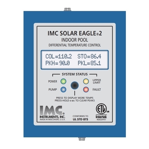
The Master LCD has a second page which will
Display the auxiliary sensor temperatures in page 2.
To select page two press the PAGE/RESET button
on the side of the LCD display momentarily. The
Auxiliary sensor will be displayed after two seconds.
To RESET the STORED PEAK temperatures of the
storage tank press and hold for 6 seconds The
PAGE/RESET button.The current temperatures will
appear after the button is released. The Master LCD
display is updated every two seconds.
Industrial Rated 400 °F(204°C) 10K IMC thermistors have +/- 1 °F accuracy. When installed, they will not exceed ONE
degree of additional error for cable distances up to 1000 feet of 18ga.; 700 feet of 20ga. or 500 feet of 22ga..
- The power terminals are for 120 vac operation. They accept gages from 14ga. to 18ga. The
power RELAY is rated for 20 Amps and is designed to connect directly to PUMPS or FANS not exceeding a total of 1hp. A 30 amp
relay option is available.
MOUNTING- The Eagle line of SOLAR controllers are designed to be mounted indoors, protected from the weather.
Use #10 screws to mount to walls.
POWER WIRING - Hard wired models are designed for 120 vac operation. All wiring is to be done in accordance with local codes.
Models supplied with line cords and receptacles are to be connected directly to power outlets with out the use of extension cords.
SENSOR INSTALLATION AND WIRING- Sensor installation should be in a manner as to permit proper sensor contact of the areas
to be measured. Shield and/or insulate the sensors to prevent them from being affected by the surrounding ambient temperatures.
Sensor wiring installed outdoors must be rated for OUTDOOR use.
Please consult local, State and federal codes for proper grounding.
SETTING UP A PC- All the EAGLE Solar controllers can be connected to the serial port of a PC or Laptop computers. An IMC DATA
PORT/RS232 adapter is required. The maximum recommended adapter cable length is 500 feet. All Windows operating systems
have a communications programs such at “TERMINAL or HYPER-TERMINAL” which are used to receive and/or CAPTURE data
from the PC serial ports. This feature is “EXTREMELY” valuable in starting up newly installed SOLAR systems. Long term Data
logging is now possible which can be very useful in service and diagnostics of intermittent malfunctions. Complete “system status”
including Temperature is presented in a line by line format including time information. Please visit our website for detailed operating
instruction at
In applications were the PC interface is going to be permanent it is recommended that an IMC serial “ISOLATED” communication
adapter be used in order to protect your PC from damaging weather related high voltage surges.
PG 2
STATUS INDICATION LEDS
SENSOR SCREW-LESS TERMINALS
- There are four status indication LEDS. The GREEN LED indicates that the microprocessor is
POWERED and the SOLAR controller is running. The BLUE LED indicates PUMP operation. If lighted the PUMP is operating and
solar energy is being stored in the STORAGE tank. The AMBER LED indicates if the UPPER LIMIT Temperature in the storage has
been exceeded. The RED LED indicates if there is a fault condition. The conditions that can cause the fault LED to turn ON are as
follows: OPEN or SHORTED or OUT of RANGE TEMPERATURE SENSORS, PUMP SWITCH “NOT” in AUTO POSITION and
internal component MALFUNCTIONS. The Red LED will always be FLASHING when the FAULT indication is ON
- The BLUE screw-less block has 9 terminals. They accept from
18ga. to 22ga. For efficient and reliable wire installation, strip 3/8” (slightly shorter than block width) of insulation from an
wire end. Use a strip tool that will the conductors. If wire is solid, make sure that the tip is not pinched or
deformed so that it will fit into the terminal hole easily. If the wire is stranded, make sure the strands are . Guide the
wire tip carefully into the terminal hole while depressing the ORANGE button directly over the hole. Pushing with your finger works,
if adjacent wires are kept from sliding out. It is easiest to insert one wire at a time using a flat blade screwdriver to depress the
appropriate button but slip off and damage any circuit components. If the wire is stranded, pay careful attention that
.
It is recommended in today’s Radio interference “RICH” environment that all sensor wiring be shielded.
The SHIELD must be brought to the shield grounding terminal located to the right of the COL sensor screw-less terminals as shown in the
controller layout diagram. For ease of shield installation, insert one short wire in the shield terminal labeled “SHLD” and connect all the
shields together with a “wire-nut”or other reliable means. Ungrounded shields may result in damage to the Solar controller circuits. The
shield requires grounding at the controller side ONLY. DO NOT attempt to ground the collector panel with the sensor shield.
COLLECTOR GROUNDING- The Solar collector panel array “must be GROUNDED’ directly to an earth ground line . This is necessary
to prevent damage from nearby lightening strikes which induce very “DAMAGING” high voltages in all nearby ungrounded metallic
surfaces.
solid or stranded wire
undamaged not nick
tightly twisted
Do not all the
strands are in the terminal properly
SENSORS -
POWER AND RELAY TERMINALS
“www.imcinstruments.com”.
INSTALLATION
All connections exposed to the weather must be made with
waterproof “outdoor” rated connectors.
Listed below are a few
suggested wire part numbers. Wire selected must also meet local codes and be rated for indoor/outdoor use by its manufacturer.
1) “PLTC” Belden # 9322 (22ga) or 9320 (20ga) Best specifications
2) “Control” Belden # 8761 (22ga) or 8762 (20ga) Better specifications
3) “Audio” Belden # 9451-10 Black (22ga) Acceptable specifications
INSTRUMENTS, INC.INSTRUMENTS, INC.
INSTRUMENTATION WITH QUALITY ENGINEERINGINSTRUMENTATION WITH QUALITY ENGINEERING


