IMC F90/010 User manual

IMC
www.imc.co.uk
Custom made mini compactor bags are available from your local dealer or www.imco.co.uk
Des sacs sur-mesure mini compactor sont disponibles chez votre revendeur local ou sur www.imco.co.uk
A34/063-R1 April 2016 ECN 8485
Waste Recycling Compactor
Installation Manual
Compacteur de déchet pour le
recyclage
Manuel d'installation
REPAIRS TO MINI COMPACTOR UNITS ARE ONLY TO BE
PERFORMED BY QUALIFIED AND ACCREDITED AGENTS. THIS
IS NOT FOR USE BY THE GENERAL PUBLIC.
Manual covers the following models:-
F90/010
F90/015
F90/030
F90/035
F90/020
F90/025
This document is protected by the copyright of, and is confidential to IMC. Unauthorised reproduction,
review or copying is in breach of that copyright and confidentiality. This document is issued in confidence
and must not be reproduced in whole or in part except under an agreement or with prior written consent of
IMC and then only on the condition that IMC copyright notice is included in such reproduction. Any
documents attached to this or any photographs, technical drawings or methodologies in this document
remain the intellectual property of IMC. This publication could contain technical inaccuracies or
typographical errors. Changes are made periodically to the information herein; these changes will be
incorporated in new editions of this publication. Any parameters or definitions are for guidance only. Some
details may differ from the requirements in your environment.

2
Index
Please read all safety information before you operate this appliance
Safety Symbols ......................................................................................................3
Safety & Pre-Installation Information ....................................................................4
Parts Supplied .......................................................................................................4
Tools Required ......................................................................................................5
Design Information................................................................................................5
Product Dimensions and Clearances ......................................................................5
Grounding Instructions and Electrical Safety..........................................................7
Installation Instructions .........................................................................................8
Unpacking .............................................................................................................8
Positioning the appliance –Important Considerations ...........................................8
Door installation....................................................................................................9
How to anchor the appliance...............................................................................11
Door Mounting Guide..........................................................................................12
3
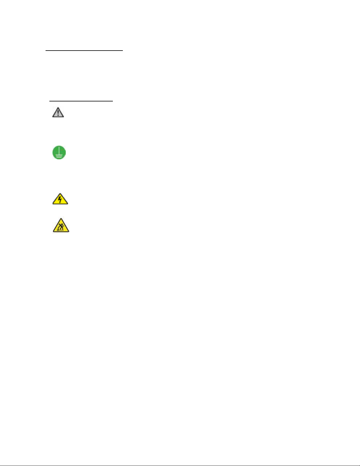
Safety Symbols
PLEASE READ BEFORE YOU COMMENCE INSTALLATION
Save these instructions
The following safety symbols are used upon your IMC appliance and supporting documentation
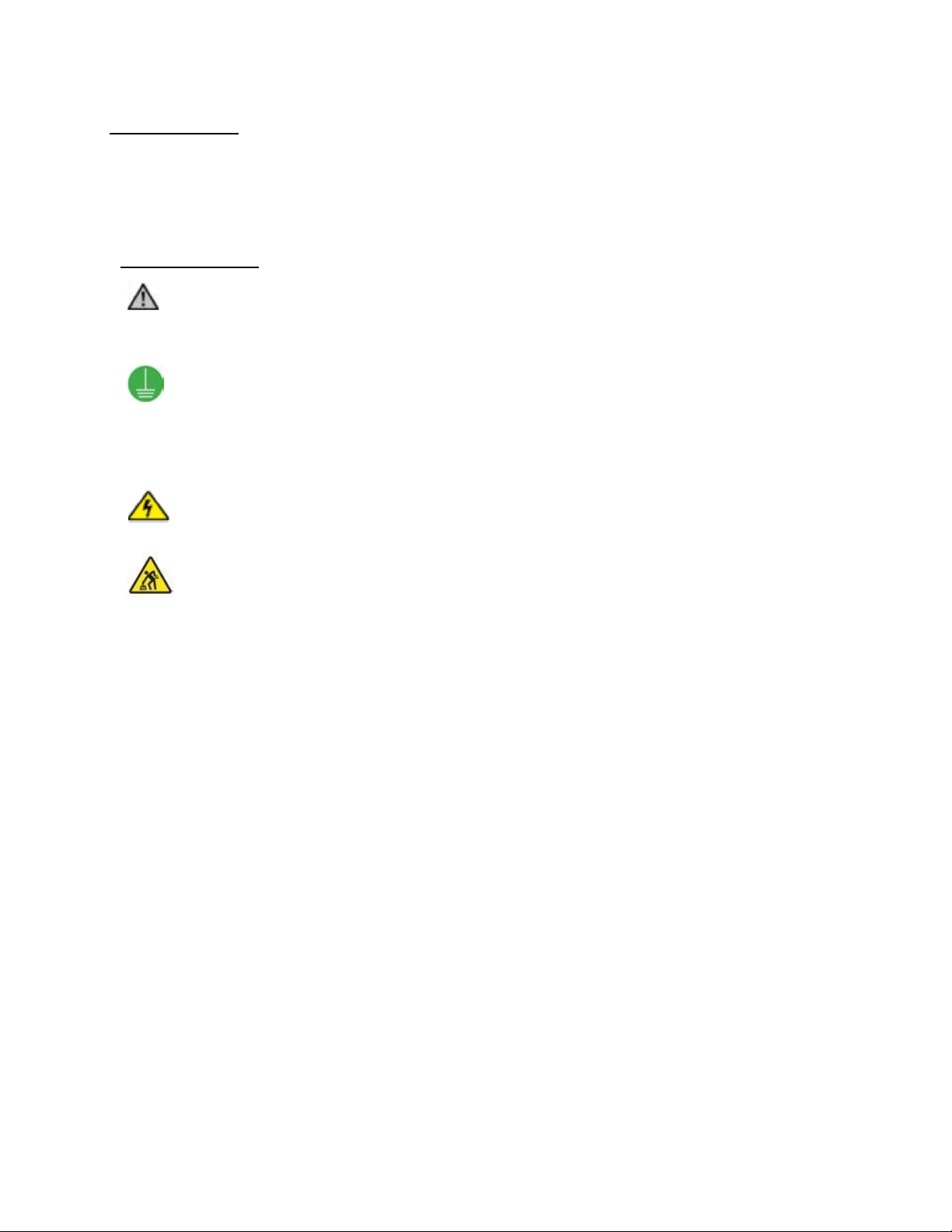
Meaning/Description
Warning/Caution
An appropriate safety instruction should be followed or caution
to a potential hazard exists
Protective
Earth/Ground
To identify any terminal which is intended for connection to an
external conductor for protection against electric shock in case
of a fault or the terminal of a protective earth (ground)
electrode
Dangerous Voltage
To indicate hazards arising from dangerous voltages
Heavy
This product is over 18 kg (40 lbs). Reference should be made
to the safety instructions for provision for lifting and moving.
Electrical rating 220-240V, 50Hz

4
Safety & Pre-Installation Information
PLEASE READ BEFORE YOU COMMENCE INSTALLATION
IMPORTANT –TO THE INSTALLER
·Keep a copy of these instructions somewhere safe
·Leave a copy of these instructions for the consumer
·Installation of this appliance requires basic mechanical and electrical skills
·Installation time –approximately 30 minutes
·Proper installation is the responsibility of the installer
·Product failure due to incorrect product installation is not covered under the warranty.
See owners User Guide
IMPORTANT –TO THE CONSUMER/OWNER
·Keep these instructions with your User Guide for future reference
·This product is for domestic use only
·This product is suitable for built-in/integrated installations ONLY
Parts Supplied
Hook Plate - To affix door
Mounting Plate - To secure door from beneath
Anchoring Plate - Floor anchor for free standing appliance
Rigidity brackets - To secure the door securely to the top of the cage
5
Tools Required
For leg adjustment - Legs are adjusted by hand –no tools required
To fix/anchor appliance to sides - Appropriate screws (NOT supplied); screwdriver
To fix/anchor appliance to floor - Appropriate floor fixing bolts or screws (NOT supplied); screwdriver
To fit door
Furniture door - Screws (screws NOT supplied); screwdriver
Stainless Steel Door - Adjustable spanner; cross head screwdriver
IMPORTANT
To ensure that no damage is caused to surrounding cabinetry ensure that you source appropriate sized
screws/fixing bolts that are no longer than the thickness of your door.
Design Information
Electrical Supply Requirements
The IMC appliance requires 220-240V, 50Hz IMC supplied from an appropriate Branch circuit protected
source
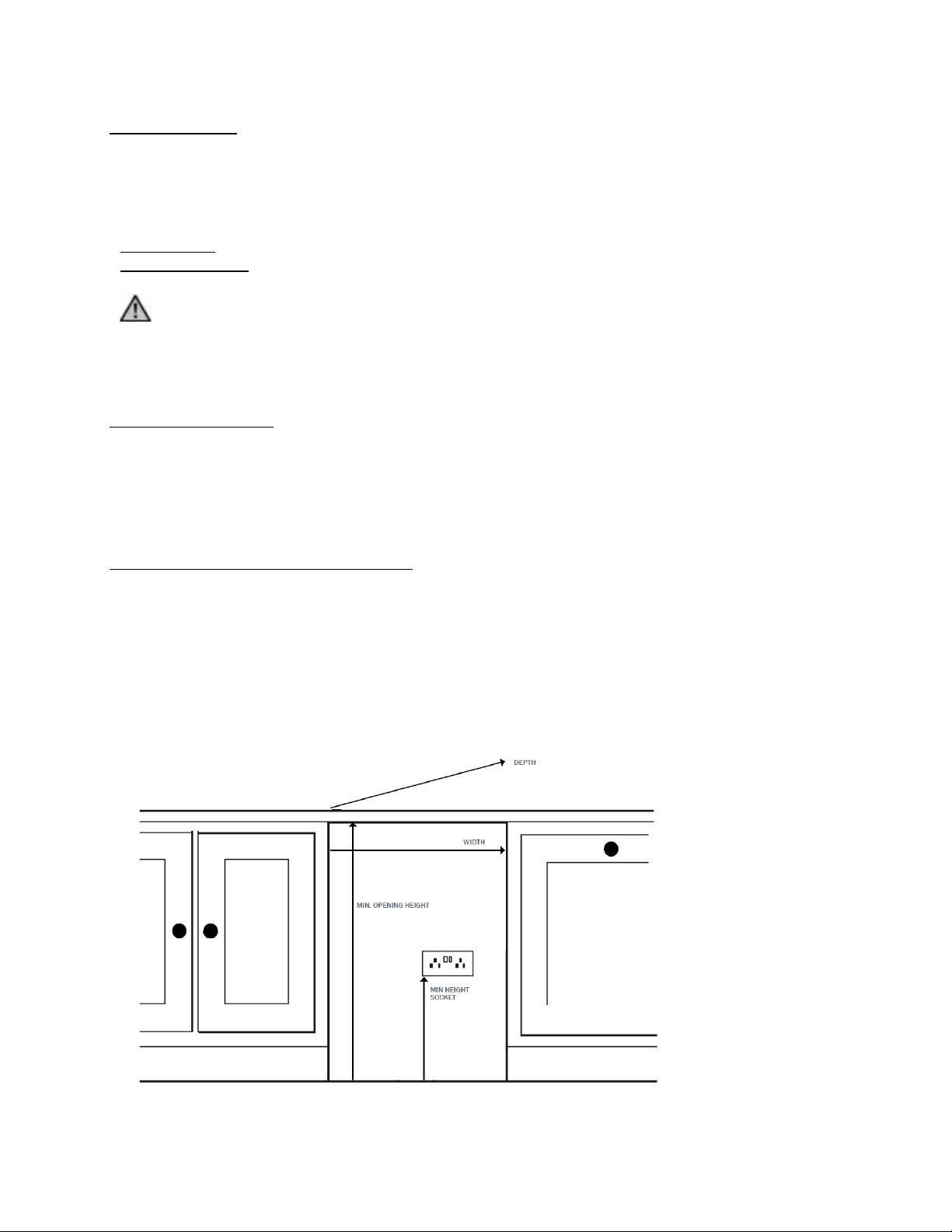
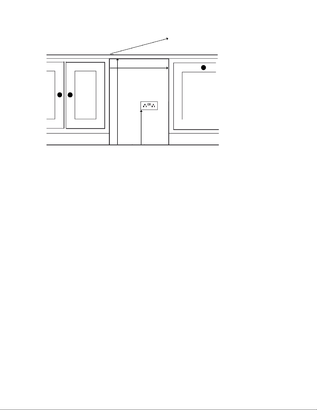
Product Dimensions and Clearances
To install the appliance, you will require the following under-counter space:
WIDTH
A minimum opening width of 300mm for a F90/010, F90/310, 400mm for a F90/030, F90/035
HEIGHT
A minimum opening height of 821mm
DEPTH
For all Models (without door) a minimum opening depth of 563mm. Ensure you have enough additional
depth to accommodate the thickness of the door being fitted

6
Allow for extra space in the depth to accommodate the plug and socket connection point. The plug socket
should be at least 440mm from the ground.
The appliance is equipped with a power cord. An electrical outlet must be provided in the under-counter
opening that meets all applicable electrical codes and requirements. See “Grounding Instructions”for
specific electrical installation details.
Under no circumstances should the appliance be operated without a main door fitted. The main door
protects the operator from the mechanism during operation.
7
Grounding Instructions and Electrical Safety
Grounding Instructions
This appliance must be grounded to a metal permanent wiring system, or an equipment grounding
conductor must be run with the circuit conductors and connected to the equipment grounding terminal or
lead on the appliance. See the installation instructions for information on electrical requirements or seek
the advice of a qualified electrician.
Electric shock could result if the electrical supply for the appliance covered in this Installation Manual is
incorrectly installed or if the appliance has been improperly grounded. Do not use the appliance if you are
not certain the electrical supply has been correctly installed or the appliance has been properly grounded.
The appliance is equipped with a three-conductor cord and three-prong grounding type plug to fit the
proper grounding type receptacle. The green –or green and yellow –coloured conductor in the cord is the
grounding wire. Never connect the green –or green and yellow –wire to a live terminal.
IMPORTANT
Where the supply cord is damaged, the cord must be replaced by the manufacturer, its service agent or
similarly qualified person in order to avoid a hazard.
WARNING –READ THESE INSTRUCTIONS THOROUGHLY BEFORE CONNECTING THIS PRODUCT TO
THE MAINS SUPPLY
Electrical Safety
Before switching on make sure that the voltage of your electricity supply is the same as that indicated on
the rating place. This appliance is for use on a nominal 240 volt circuit.
This appliance is fitted with a non-rewireable plug. Should the supply cord become damaged it should be
replaced by a qualified service technician.
Unplug the appliance from outlet before servicing
Do not modify the plug attached to the appliance
Use only with a grounded receptacle
When not in use or uninstalled the appliance should be kept in a clean, cool and dry environment and
with the main door firmly closed. The power cord must be kept away from any heat source and sharp
instruments.

8
Installation Instructions
Unpacking
IMPORTANT - Provisions for lifting and carrying should be made as this product weights over 18kg (40
lbs)
Remove the appliance from its packaging.
Positioning the appliance –Important Considerations
Leg Adjustment
Prior to installation ensure that you have the appropriate size under-counter space. Please see “Product
Dimensions and Clearances”on page 5 for further details.
Slide the appliance next to the designated under-counter space and measure the distance that the legs will
need to be adjusted in order to elevate the appliance to the correct height for your worktop/counter.
To reduce or increase the leg height, simply loosen and spin the leg. Adjust the legs to just short of the
proposed height so that the appliance will slot into the allocated space easily. You might want to consider
using a lever under the appliance to lift it up, or a G-clamp to hold the top of the appliance under the
worktop/carcass. Plug the appliance into the electrical socket (switched on) and slide it into the space.
Door allowance
MOST IMPORTANT - When positioning the appliance into the space it is imperative to make appropriate
allowance for the thickness of the door. The front fascia of the appliance must not be set too far back. Any
gap between the front fascia of the appliance and the closed door will prevent the safety micro switches from
connecting preventing operation of the appliance. Ensure the appliance is set far enough forward within the
under-counter space so that the door shuts tight against the appliance front fascia and also flush with any
surrounding cabinetry.
Ensure that you test the micro switches once you have fitted the door and BEFORE you permanently anchor
the appliance. To test the micro switches open and close both the main door (with Main Collection Bin cage
attached) and Can Collection Drawer (Models F90/030, F90/035) listen carefully for a double click of the micro
switches when you close the door/drawer.
Worktop clearance for removal of the Main Collection Bin
During installation of the appliance you will need to assess the ease by which the Main Collection Bin can be
removed. This is particularly relevant where a work surface (including any grab rail attached to the work
surface) overhangs the appliance. The closer the top of the appliance to the work surface, the more acute the
angle is in order to remove the Main Collection Bin. To avoid problems in removal of the Bin and or its
contents, it is recommended that the work surface (including any grab rail) does not overhang by more than
20 mm.

9
Door installation
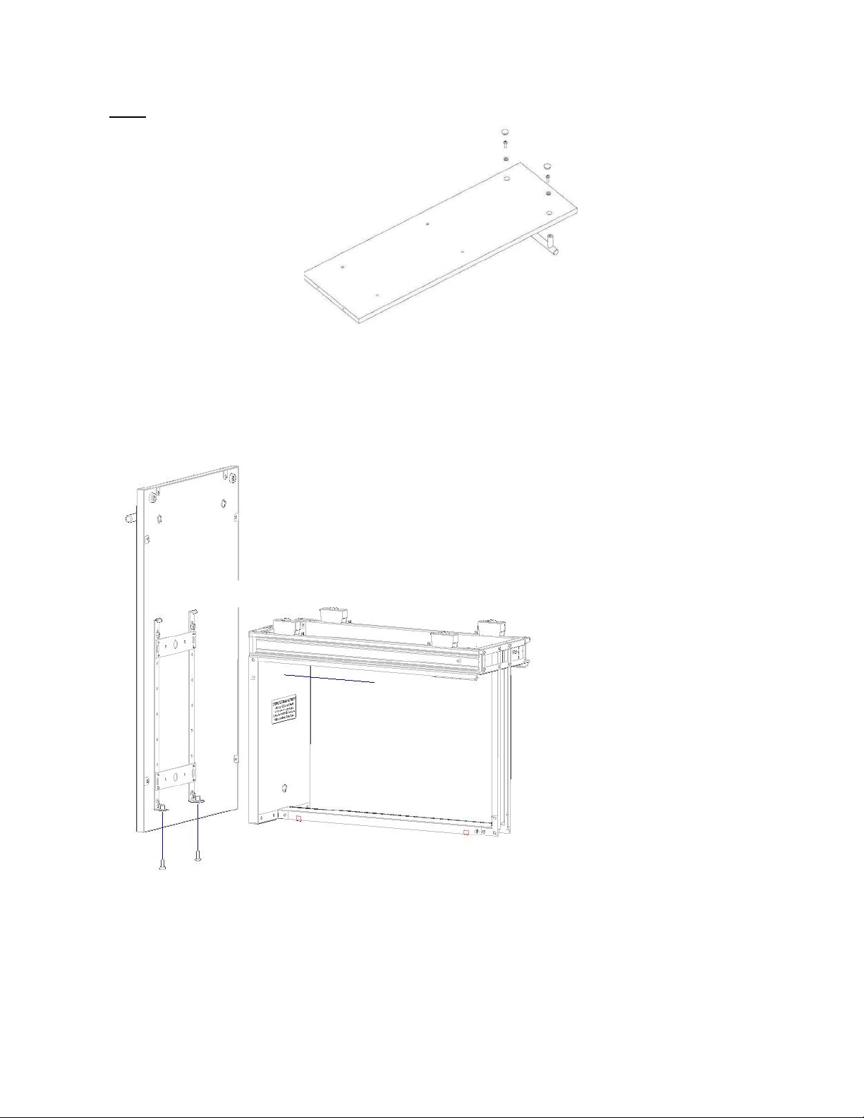
Step 1
IMC stainless steel doors are supplied
with predrilled holes.
For other furniture doors you are
required to drill the screw holes into the
door according to the position as illustrated
in Dia. 1. A detailed hole position
template can be found in “Door Mounting
Guide”.
WARNING
Take great care NOT to drill right through
the door. All models will accommodate
either an IMC stainless steel door or
other furniture door. For furniture doors
with panels it would be advisable to add
an additional wood panel to the rear of the door to provide additional strength.
Step 2
Attach the mounting plate to
the door –as illustrated in
Diagram 2
Dia. 2
2 x Handle mount holes
(S model only)
4 x Door mount holes
(not ‘through’holes)
Dia. 1
10
Step 3
If fitting an IMC stainless steel
door you may need to attach
the handle by placing the
handle in position and fully
tighten the securing bolts. Fit
plastic caps over the bolts.
(Dia. 3)
Step 4
Next hang the door in position by aligning the 4 hooks on the hook plate over the keyway slots on the door
cage (Dia. 4).
Dia. 3
Dia. 4

11
How to anchor the appliance
The appliance must be anchored securely. This can be done by securing the appliance to adjoining cabinetry
by screwing the appliance sideways into the adjoining carcass/cabinetry (Dia. 8).
Dia. 8
FLOOR MOUNTING
BRACKET (S MODELS)
INSTALLATION
HOLES

12
Door Mounting Guide
Important - rear of door shown
Model
A
B
C
F90/010, F90/015
298
63
74
F90/030, F90/035
398
41
52
HANDLE THROUGH HOLES
(POSITION AS APPROPRIATE)
DOOR RIGIDITY BRACKET
POSITIONS
(PILOT HOLE FOR SCREWS
ONLY NOT THRU HOLES)
HOOK
PLATE
SECURING
POINTS
(PILOT HOLE FOR
SCREWS ONLY
NOT THRU
HOLES)

13
Index
Veuillez lire toutes les informations sur la sécurité avant d'utiliser cet appareil
Symboles sur la sécurité...................................................................................... 14
Informations sur la sécurité et la pré-installation ................................................ 15
Éléments fournis................................................................................................. 15
Outils nécessaires ............................................................................................... 16
Information sur la conception ............................................................................. 16
Dimensions du produit et espaces nécessaires.................................................... 16
Instructions de mise à la terre et sécurité électrique........................................... 18
Notice d’installation............................................................................................ 19
Déballage............................................................................................................ 19
Positionnement de l'appareil - Considérations importantes ................................ 19
Installation de la porte........................................................................................ 20
Comment ancrer l'appareil.................................................................................. 22
Guide de fixation de porte .................................................................................. 23
14
Symboles sur la sécurité
VEUILLEZ LIRE CECI AVANT DE COMMENCER L'INSTALLATION
Conservez ces instructions
Les symboles de sécurité suivants sont utilisés avec votre appareil Krüshr et la documentation de soutien
Signification / Description
Avertissement / précaution
Des précautions de sécurité appropriées doivent être suivies là
où des instructions concernant un danger potentiel sont
indiquées
Protection sol / terre
Pour identifier un terminal conçu pour une connexion à un
conducteur externe pour la protection contre les électrochocs
en cas de panne ou le terminal d'une électrode de protection
sol (terre)
Tension dangereuse
Pour indiquer les dangers provenant de tensions dangereuses
Lourd
Ce produit pèse plus de 18 kilos (40 livres). Il est nécessaire de
consulter les instructions de sécurité lors du déplacement et du
soulèvement.
Caractéristiques électriques 220-240 V, 50 HZ

15
Informations sur la sécurité et la pré-installation
VEUILLEZ LIRE CECI AVANT DE COMMENCER L'INSTALLATION
IMPORTANT –POUR L'INSTALLATEUR
·Conservez une copie de ces instructions en sécurité
·Laissez une copie de ces instructions pour le client
·L'installation de cet appareil nécessite des compétences de base en mécanique et
électricité
·Durée d'installation - environ 30 minutes
·L'installation correcte est la responsabilité de l'installateur
·Une panne du produit due à une installation incorrecte du produit n'est pas couverte par
la garantie. Consultez la guide d'utilisation du propriétaire
IMPORTANT –AU CLIENT/UTILISATEUR
·Gardez ces instructions avec le guide de l'utilisateur pour référence ultérieure
·Cet appareil est uniquement à usage domestique
·Ce produit ne convient QUE pour des installations intégrées
Éléments fournis
Plaque crochet - Pour fixer la porte
Plaque de montage - Pour fixer la porte de derrière
Plaque d'ancrage - Ancrage au sol pour un appareil tenant sans support
Crochets de rigidité –Four fixer la porte fermement en haut de la cage

16
Outils nécessaires
Pour le réglage des pieds - Les pieds sont ajustés à la main, pas d'outil nécessaire
Pour fixer/ancrer l'appareil sur les côtés - Vis appropriées (NON fournies) ; tournevis
Pour fixer/ancrer l'appareil au sol - Vis ou boulons appropriés (NON fournis) ; tournevis
Pour fixer la porte
Porte meuble - Vis (vis NON fournies) ; tournevis
Porte en acier inoxydable - Entretoise réglable ; tournevis cruciforme
IMPORTANT
Pour garantir qu'aucun dégât n'est causé aux placards environnant, assurez-vous d'utiliser des vis/boulons
de fixation de la taille approprié dont la longueur ne dépasse pas l'épaisseur de votre porte.
Information sur la conception
Besoin d'alimentation électrique
L'appareil IMC fonctionne sur une alimentation 220-240V, 50Hz, depuis une source protégé de circuit par
dérivation approprié.
Dimensions du produit et espaces nécessaires
Pour installer l'appareil, vous devrez respecter les espaces minimum suivants sous le comptoir :
LARGEUR
Une largeur d'ouverture minimum de 300 mm pour le F90/010, F90/015, 400 mm pour le F90/030,
F90/035
HAUTEUR
Une hauteur d'ouverture minimum de 821 mm
PROFONDEUR
Pour tous les modèles (sans porte), une profondeur d'ouverture minimum de 563 mm. Assurez-vous
d'avoir suffisamment de profondeur pour loger l'épaisseur de la porte installée.
17
Laissez suffisamment d'espace libre dans la profondeur pour installer la prise et le point de connexion à la
fente. La prise doit être au moins à 440 mm du sol.
L'appareil est équipé d'un cordon d'alimentation. Une prise secteur doit être disponible en dessous de
l'ouverture du comptoir respectant toutes les régulations et réglementations électriques applicables. Voir
les « Instructions de mise à la terre » pour les détails spécifiques à l'installation électrique.
L'appareil ne doit sous aucunes circonstances fonctionner sans une porte principale équipée. La porte
principale vous protégera contre le mécanisme pendant le fonctionnement.
PROFONDEUR
LARGEUR
MIN. HAUTEUR D'OUVERTURE
FENTE DE HAUTEUR
MINIMUM

18
Instructions de mise à la terre et sécurité électrique
Instructions de mise à la terre
L'appareil doit être mis à la terre sur un système de câblage permanent en métal, ou un équipement de
conducteur de mise à la terre doit être utilisé avec des conducteurs de circuit et connecté au terminal de
mise à la terre de l'équipement ou un plomb sur l'appareil. Consultez les instructions d'installation ou les
conditions électriques ou demandez le conseil d'un électricien qualifié.
Un électrochoc peut se produire si l'alimentation électrique pour l'appareil présenté dans ce guide
d'installation est incorrectement installée ou si l'appareil n'a pas été correctement relié à la terre.
N'utilisez pas l'appareil si vous n'êtes pas certain que l'alimentation électrique a été correctement
installée ou si l'appareil n'a pas été correctement relié à la terre.
L'appareil est équipé avec un cordon à trois conducteurs et une prise terre à trois fiches pour s'adapter au
réceptacle de type terre approprié. Le conducteur coloré vert ou vert et jaune dans ce cordon est le fil de
mise à la terre. Ne connectez jamais le fil vert, ou vert et jaune, à un terminal actif.
IMPORTANT
Si le câble d’alimentation est endommagé, il doit être remplacé par le fabricant ou son prestataire de
service, ou un technicien qualifié, afin d’éviter tout risque inutile.
AVERTISSEMENT –LISEZ ATTENTIVEMENT CES INSTRUCTIONS AVANT DE CONNECTER CE PRODUIT
SUR L'ALIMENTATION SECTEUR
Sécurité électrique
Avant d'allumer, assurez-vous que la tension de votre alimentation électrique est la même que celle
indiqué sur la plaque signalétique. Cet appareil est conçu pour une utilisation sur un circuit de 240 volts
nominaux.
Cet appareil est équipé d'une prise ne pouvant être re-câblée. Si le cordon d’alimentation est
endommagé, il doit être réparé par un technicien qualifié.
Débranchez l'appareil du secteur avant de réparer
Ne modifiez pas la prise attachée à l'appareil
N'utilisez qu'avec un réceptacle mise à la terre
Lorsqu'il n'est pas utilisé ou désinstallé, l'appareil doit être gardé dans un environnement propre, frais et
sec et avec la porte principale bien fermée. Le cordon d'alimentation doit être tenu éloigné de toute
source de chaleur et des instruments coupants.

19
Notice d’installation
Déballage
IMPORTANT - Des précautions pour soulever et déplacer doivent être prises car ce produit pèse plus de
18 kilos (40 livres)
Sortez l'appareil de son emballage.
Positionnement de l'appareil - Considérations importantes
Réglage des pieds
Avant l'installation, assurez-vous de disposer de l'espace suffisant en dessous de l'espace du comptoir.
Veuillez consulter « Dimensions du produit et espaces nécessaires » en page 5 pour plus de détails.
Faites glisser l'appareil à côté de l'espace préparé sous le comptoir et mesurez la distance à laquelle les pieds
devront être réglés afin d'élever l'appareil à la hauteur correcte pour votre plan de travail/comptoir.
Pour diminuer ou augmenter la hauteur des pieds, desserrez simplement et dévissez le pied. Réglez les pieds
légèrement plus bas que la hauteur proposée afin que l'appareil se fixe dans l'espace réservé facilement. Vous
souhaiterez peut-être laisser un levier sous l'appareil pour le soulever, ou un serre-joint pour maintenir le
haut de l'appareil sous le plan de travail/carcasse. Branchez l'appareil dans une fente électrique (allumée) et
faites-la glisser dans l'espace.
Espace pour la porte
TRÈS IMPORTANT - Lorsque vous positionnez l'appareil dans l'espace, il est impératif de laisser l'espace
nécessaire pour l'épaisseur de la porte. La face avant de l'appareil ne doit pas être installée trop loin en
arrière. Tout espace entre la face avant de l'appareil et la porte fermée empêchera les micro-interrupteurs de
sécurité de se connecter et empêcheront le fonctionnement de l'appareil. Assurez-vous que l'appareil est
placé suffisamment en avant dans l'espace sous le comptoir afin que la porte se ferme à proximité de la face
avant de l'appareil et soit également à une distance suffisante des placards adjacents.
Assurez-vous de bien tester les micro-interrupteurs une fois que vous avez fixé la porte et AVANT d'ancrer
l'appareil de manière permanente. Pour tester les micro-interrupteurs, ouvrez et fermez la porte principale
(avec la cage de corbeille de collecte principale attachée) et le tiroir de collecte de cannettes (modèles
F90/030, F90/035) et écoutez attentivement le double clic des micro-interrupteurs lorsque vous fermez la
porte/le tiroir.
Dégagement du plan de travail pour enlever la corbeille de collecte principale
Pendant l'installation de l'appareil, vous devrez évaluer l'espace nécessaire pour enlever facilement la
corbeille de collecte principale. Cela est particulièrement important lorsqu'une surface de travail (y compris le
rail d'accroche attaché à la surface de travail) surplombe l'appareil. Plus le dessus de l'appareil sera proche du
plan de travail, plus l'angle sera aigu pour enlever la corbeille de collecte principale. Pour éviter les problèmes
lors de l'enlèvement de la corbeille et de son contenu, il est recommandé que le plan de travail (y compris le
rail d'accroche) ne surplombe pas de plus de 20 mm.

20
Installation de la porte
Étape 1
Étape 2
Étape 3
Si vous installez une porte en
acier inoxydable Krüshr, vous
aurez peut-être besoin
d'attacher la poignée en la
positionnant et en serrant
complètement les boulons de
fixation. Installez les têtes en
plastique sur les boulons.
(Schéma 3)
Schéma 2
Schéma 1
Schéma 3
This manual suits for next models
5
Table of contents
Languages:
Other IMC Trash Compactor manuals


Popular Trash Compactor manuals by other brands

Electrolux
Electrolux EI15TC65HS - Undercounter Trash Compactor Factory parts catalog

Broan
Broan Elite 15XESSEXF Service manual

NuTone
NuTone 1050 Specification sheet

KitchenAid
KitchenAid 4KUCS181T Use and care guide

CRAM-A-LOT
CRAM-A-LOT SC-T1 Operator's instruction manual

Whirlpool
Whirlpool W10318827C Use & care guide


