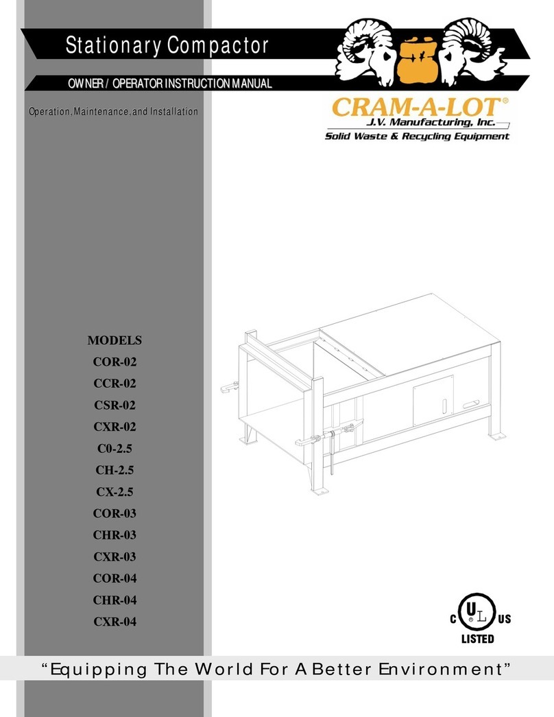
CRAM-A-LOT SC-T1 Assembly instructions

MODELS
SC-T1
SC-T2
SC-02
SC-T1-HTG
SC-T1-HTG-SP
SC-T2-HTG
SC-T2-HTG-SP
“Equipping The World For A Better Environment”
OWNER / OPERATOR INSTRUCTION MANUAL
Operation, Maintenance, and Installation

2

Congratulations
You have just purchased a quality designed and manufactured CRAM-A-LOT® Compactor.
Manufacturing compactors and balers since 1978, JV Manufacturing offers quality workmanship, factory trained installa-
tion and a national service network. Advanced features have been designed into the compactor for modern waste dispos-
al operations.
As with any investment, a return is expected, and the return received from this investment will be in the form of maximum
performance during many years of dependable service.
In order to maintain quality performance and safe operation of your new compactor, it is necessary to observe and prac-
tice the operation and maintenance information provided in this manual.
The employer involved in the operation, maintenance, and installation of the compactor should read and understand the
most current version of the following applicable standards.
ANSI Standard No. Z245.2, “Stationary Compactors-Safety Requirements for Installation, Maintenance and Operation”.
A copy of this standard may be obtained from:
NATIONAL WASTE AND RECYCLING ASSOCIATION
4301 Connecticut Avenue, NW
Washington D.C. 20008
Website http://wasterecycling.org
If, after thoroughly reading this manual, there are questions about the operation or repair of your compactor, please con-
tact J.V. Manufacturing, Inc., and our Customer Support Team will provide assistance.
CRAM-A-LOT® Customer Support
Tel: 800-754-4290
Fax: 479-751-7870
Hours: 7:00 am - 5:00 pm CST®
Monday - Friday
JV Manufacturing Corporate Philosophy
It is the stated goals of J.V. Manufacturing, Inc. to build equipment of uncompromising quality, provide the absolute best
customer service in our industry, and to conduct all business with honesty and integrity, whether it be with customers,
vendors, fellow employees or members of the community.
J.V. Manufacturing, Inc. encourages positive change. Change will provide opportunities for future growth and new direc-
tions as we move into the future.
3

4

Table of Contents
Manual0007 Rev. G. Effective 6/14/2019
Introduction
Congratulations................................................................................................................................. 3
Table of contents............................................................................................................................... 5
Specifications................................................................................................................................. 6-9
Operation Section
Decals ............................................................................................................................................. 12
Safety Decal Placement.................................................................................................................. 13
Compactor Operation
Safety Orientation .................................................................................................................... 14
Owner/employer Responsibilities............................................................................................. 15
Operator and Employee Responsibilities ................................................................................. 16
Procedure for control of hazardous energy sources ................................................................ 16
Safety and Training program ................................................................................................... 17
General Training ...................................................................................................................... 17
Compactor Controls ................................................................................................................. 18
Standard Operation Sequence................................................................................................. 19
Emergency Procedures ........................................................................................................... 19
User Preventive Maintenance.................................................................................................. 20
Maintenance Section
Lockout & Tag-out Instructions ....................................................................................................... 22
Hydraulic Safety.............................................................................................................................. 23
Preventive Maintenance.................................................................................................................. 24
Checking and adding oil........................................................................................................... 23
Electric Schematics......................................................................................................................... 26
Hydraulic Schematics................................................................................................................. 27-28
Trouble-Shooting Chart................................................................................................................... 29
Installation Section
Installation Requirements
Concrete Pad ......................................................................................................................... 35
Positioning ............................................................................................................................. 35
Anchoring............................................................................................................................... 35
Electrical & Hydraulic Installation ........................................................................................... 36
5
3-10
11-20
21-29
34-36
Warranty Policy & Procedures Section 39-42
Warranty Policy .......................................................................................................................... 39-41
Warranty Procedures ...................................................................................................................... 42
Hauler Section
Hauler Operation Instructions ......................................................................................................... 38
37-38
Parts Section
Ram Assembly T2 Parts.................................................................................................................. 31
Ram Assembly 02 Parts.................................................................................................................. 32
30-33

6
Specifications
A
(OAW)
C
(OAL)
B
(OAH)
MODEL A (OAW) B (OAH) C(OAL) WEIGHT (lbs)
SC-T1-10 8’-1” 7’-3” 12’-11” 6,500
SC-T1-15 8’-1” 7’-3” 16’-3” 7,000
SC-T1-20 8’-1” 7’-3” 19’-7” 7,500
SC-T2-20 8’-3” 8’-7” 17’-1” 9,800
SC-T2-25 8’-3” 8’-7” 19’-8” 10,200
SC-T2-30 8’-3” 8’-7” 21’-10” 10,600
SC-T2-34 8’-3” 8’-7” 23’-6” 10,800
SC-T2-38 8’-3” 8’-7” 25’-7” 11,000
SC-02-20 8’-3” 8’-7” 18’-9” 10,000
SC-02-25 8’-3” 8’-7” 21’-4” 10,400
SC-02-30 8’-3” 8’-7” 23’-6” 10,800
SC-02-34 8’-3” 8’-7” 25’-2” 11,000

7
Specifications
Hydraulic Tailgate
MODEL A(OAW) B (OAH) C (OAL) WEIGHT (lbs)
SC-T1-16-HTG 8’-5 1/4” 7’-9” 17’-11 1/2” 8,000
SC-T1-16-HTG-SP 8’-5 1/4” 7’-9” 17’-11 1/2” 8,200
SC-T1-20-HTG 8’-5 1/4” 7’-9” 19’-5 3/4” 8,200
SC-T1-20-HTG-SP 8’-5 1/4” 7’-9” 19’-5 3/4” 8,400
SC-T1-25-HTG 8’-5 1/4” 7’-9” 22’-11 1/2” 8,530
SC-T2-20-HTG 8’-5 1/2” 9’-2” 17’-1/2” 10,260
SC-T2-20-HTG-SP 8’-5 1/2” 9’-2” 17’-1/2” 10,610
SC-T2-25-HTG 8’-5 1/2” 9’-2” 19’-7 1/2” 10,900
SC-T2-25-HTG-SP 8’-5 1/2” 9’-2” 19’-7 1/2” 11,250
SC-T2-30-HTG 8’-5 1/2” 9’-2” 21’-9” 11,540
SC-T2-30-HTG-SP 8’-5 1/2” 9’-2” 21’-9” 11,890
SC-T2-34-HTG 8’-5 1/2” 9’-2” 23’-5” 12,800
SC-T2-34-HTG-SP 8’-5 1/2” 9’-2” 23’-5” 13,394

8
J.V. MANUFACTURING, INC
SC-02, SC-T1 and SC-T2 SPECIFICATIONS
General Equipment Specifications SC-02 SC-T1 SC-T2
Wastec Charge Box Rating 1.31 cu/yd .73 cu/yd 1.52 cu/yd
Clear Top Opening 34”x58” 31”x46” 41”x58”
Cycle Time (sec) 37 28 42
System Pressure (psi) Normal 2,000 2,000 2,000
Maximum 2,400 2,400 2,400
Compaction Force (lbs) Normal 39,300 44,200 42,600
Maximum 47,100 53,000 51,100
Ram Face Pressure (psi) Normal 22.6 40 24.5
Maximum 27.1 48 29.5
Ram Penetration 5.5” 6” 8”
Motor (hp) 10 10 10
Motor (voltage) 208/230/480 3ph 208/230/480 3ph 208/230/480 3ph
Pump (capacity) (gpm) 10.5 10.5 10.5
Reservoir capacity (gal) 22 22 22
Cylinder
Bore 5” 4” (2) 4” (2)
Stroke 40” 26” 34”
Rod 2.5” 2” 2”
Construction
Floor
1/2” steel plate 1/2” steel plate 1/2” steel plate
1/4” steel truss type structure 4” “C” Channel 1/4” steel truss type structure
Sides
3/16” steel plate 3/16” steel plate 3/16” steel plate
2”x6”x3/16” steel tube
6” “C” Channel 4” “C” Channel 4” “C” Channel
Breaker Bar 6”x6”x3/4” steel angle 6”x6”x1” steel angle 6”x6”x1” steel angle
Ram
Top 3/16” steel plate 3/16” steel plate 3/16” steel plate
Sides 1/4” steel plate 3/16” steel plate 1/4” steel plate
Bottom 1/2” AR steel plate 1/2” AR steel plate 1/2” AR steel plate
Face 3/8” wedge face steel 1/2” steel plate 1/2” steel plate
Guides UHMW pads UHMW pads UHMW pads

9
J.V. MANUFACTURING, INC
SC-T1-HTG and SC-T2-HTG SPECIFICATIONS
General Equipment Specifications SC-T1 SC-T2
Wastec Charge Box Rating .86 cu/yd 1.45 cu/yd
Clear Top Opening 31”x48” 41”x58”
Cycle Time (sec) 28 42
System Pressure (psi) Normal 2,000 2,000
Maximum 2,400 2,400
Compaction Force (lbs) Normal 40,600 40,600
Maximum 48,800 48,800
Ram Face Pressure (psi) Normal 36.7 23.3
Maximum 44.2 28.0
Ram Penetration 6” 8”
Motor (hp) 10 10
Motor (voltage) 208/230/480 3ph 208/230/480 3ph
Pump (capacity) (gpm) 10.5 10.5
Reservoir capacity (gal) 22 22
Cylinder
Bore 4” (2) 4” (2)
Stroke 26” 34”
Rod 2” 2”
Construction
Floor
1/2” steel plate 1/2” steel plate
4” “C” Channel 1/4” steel truss type structure
Sides
3/16” steel plate 3/16” steel plate
2”x6”x3/16” steel tube
4” “C” Channel 4” “C” Channel
Breaker Bar 6”x6”x1” steel angle 6”x6”x1” steel angle
Ram
Top 3/16” steel plate 3/16” steel plate
Sides 3/16” steel plate 1/4” steel plate
Bottom 1/2” AR steel plate 1/2” AR steel plate
Face 1/2” steel plate 1/2” steel plate
Guides UHMW pads UHMW pads

10

11
Operation
Section

12
SAFETY DECALS

13
SAFETY DECAL PLACEMENT

14
Compactor Operation
Safety Orientation
Safe Operation
CRAM-A-LOT® compactors meet or exceed all safety standards set by ANSI. Although we have included many safety features in
the design and construction of your compactor, safe operation of the equipment depends on the operator's adherence to certain
guidelines. To prevent accidents to personnel or damage to the compactor, the operator must NEVER VIOLATE ANY OF THE
FOLLOWING SAFETY PRECAUTIONS. It is the owner / employer’s responsibility to ensure these guidelines are known and
followed by all operators of the compactor.
NOTE: Publication of these safety precautions does not imply or represent an inclusive list.
NEVER place hands or arms in the compactor while it is operating.
NEVER allow anyone except qualified electrical or hydraulic repair persons to work on the equipment.
NEVER disable any safety switch.
NEVER overload the compaction chamber.
NEVER place concrete, heavy steel plate or castings, explosive materials, liquids, nor hazardous waste in the compactor .
NEVER climb in or on the compactor, nor perform any maintenance/repairs unless the power is disconnected and locked /
Tagged out.
NOTE: Hydraulic oil is the primary element of power transmission on the compactor. Remember that hydraulic systems can
remain pressurized even after the motor has stopped and or the power disconnected. Refer to the Lock Out / Tag Out instruc-
tions found elsewhere in this manual for instructions concerning the neutralization of these energy sources.
Z245.2—2013
Stationary compactors—safety requirements for installation, maintenance and operation.
Obtain a copy of this standard (ref: http//wasterecycling.org) and become familiar with specific responsibilities and guidelines.
Safety Terminology
The accident prevention decals on your CRAM-A-LOT® compactor meet or exceed standards set by ANSI and OSHA. It is im-
portant that you are familiar with the terminology used on the decals and the varying degrees of hazards that are associated with
this terminology.
DANGER—Indicates an imminently hazardous situation which, if not avoided, will result in death or serious injury. This signal
word is to be limited to the most extreme situations. The signal word Danger should not be used for property damage hazards
unless personal injury risk appropriate to the level is also involved.
WARNING—Indicates a potentially hazardous situation which, if not avoided, could result in death or serious injury. This signal
word should not be used for property damage hazards unless personal injury risk appropriate to this level is also involved.
CAUTION—Indicates a potentially hazardous situation which, if not avoided, may result in minor or moderate injury. It may also
be used to alert against unsafe practices that may also cause property damage.
NOTICE—Indicates a statement of company policy directly or indirectly related to the safety of personnel or protection of property.
This signal word should not be associated directly with a hazard or hazardous situation.

15
Compactor Operation, cont.
Owner/employer responsibilities for compactors The employer/owner shall provide properly
Maintained stationary compactors that meet all applicable regulatory safety requirements and requirements of ANSI Z245.2-2013.
AEnsuring that the installation of the compactor conforms to local, state and federal codes, ordinances, and manufacturer’s
recommendations. If installing into a system, examine prevailing safety standards of associated equipment.
BProviding to employees instruction and training in safe work methods before assigning them to operate , clean, service,
maintain, modify, or repair the compactor. Such instruction and training shall include procedures provided by the manufac-
turer. The employer will maintain records as to the names of employees and the dates of training.
CProviding instructions for addressing abnormal situations (e.g., bridging of the loading chamber or feeding chute, jam of
materials).
DAssigning only trained employees to work on (which includes operating, loading, cleaning, servicing, maintaining, or repair-
ing) the compactor.
EMonitoring the employee’s operation of the compactor and take appropriate action to insure proper use, including adher-
ence to safe practices and the employee requirements of Z245.2-2013.
FRepairing, prior to placing the compactor into service, any mechanical malfunctions or breakdowns that effect the safe op-
erations of the compactor.
GEstablishing and following a program of periodic and regular inspections of all compactors to insure that all parts, compo-
nent equipment, and safeguards are in safe operating condition, and adjusted, in accordance with the manufacture’s rec-
ommended procedures. This shall include keeping all malfunction reports and records of inspections and maintenance
work performed.
HImplementing a program for the maintenance of the compactor which will incorporate the following elements:
1) Requirements for trained, competent maintenance employees or contractors to perform inspection and repair
work;
2) Providing for the cleaning, inspection and repair of the compactor in accordance with the manufacture’s recom-
mendations. Including periodic maintenance;
3) Ensuring that all required safety features are operational and functioning, and repairing, prior to placing into ser-
vice, any reported malfunction or defect that affects the safe operation of the compactor;
4) Ensuring that all caution, warning and danger markings required are installed and legible, or are replaced if dam-
aged, defaced or missing.
IUtilizing the owner/employers written and manufacturer’s recommended procedures for the control of hazardous energy
sources (lockout/tag-out) in a program complying with OSHA 29 CFR Subpart S, Electrical; ANSI/NFPA 70E.
JUtilizing the owner/employers written instructions and manufacture’s recommended procedures for access control for per-
mit-required confined spaces as part of the employer’s program;
KProtecting any person by one of the methods in 5.9.1, AMERICAN NATIONAL STANDARD Revision of ANSI Z245.2-
2013, or by other means as effective as those means of protection.
LFor compactors fed by means of a loading pit conveyor, reciprocating floor or push pit that is flush with or below the facility
floor, provide;
1. Protection for employees by means of ;
a) Limiting access within 6 feet (183) of the edge of the pit to authorized employees;
b) Training authorized employees to recognize and avoid the hazards associated with the pit area;
c) Requiring that others whose employees use the pit area provide assurance of such training;
d) Limiting access by unauthorized persons by installing signs, such as:
“RESTRICTED AREA - AUTHORIZED EMPLOYEES ONLY”
2. Providing a device to the extent practicable, which prevents trucks or other motor vehicles that unload directly into
the loading pit from rolling into the pit.
MWhen compactor equipped with automatic start/cycling controls are provided, allowing their use only in locations where a
startup alarm is utilized or it is demonstrated that automatic starting does not result in a risk of injury to persons;
NProviding guard railings for dock ramps that meet U.S. Occupational Safety and Health Administration requirements. These
shall be located around the loading chamber if walk on ramps are used to deposit refuse into the loading chamber. Guard
railings and toe boards shall be provided on the sides of docks and ramps;
OProviding for an adequate work area around the compactor for safe maintenance, servicing, and cleaning procedures.
PKeeping all surrounding walking areas and floor free from obstructions, and from accumulations of waste matter, grease, oil
and water;
QMaintaining records or employees reports of malfunctions.
RSpecifically inspecting safety interlocks, switches, and other protective devices to ensure that these devices are not disa-
bled or bypassed, and not to permit the compactor to be operated unless these devices are fully functional. These inspec-
tions shall be in accordance with ‘G’;
SEnsuring that containers supplied are capable of withstanding the maximum forces generated by the compacting system;
TEnsuring that loaders are aware of hazards and safety requirements;
UEnsuring that only authorized employees (18 years or older) operate, inspect, or maintain compactors;
VIncorporating compactors into the employer’s safety program.

16
Compactor Operation, cont.
Operator and employee responsibilities for compactors Operators who work on and around
the compactor shall be responsible for the items listed below:
A. Using all applicable safety features provided on the compactor;
B. Using the compactor only after reading and receiving instruction and training;
C. Reporting any damage to, or malfunction of the compactor by submitting a report to the employer or responsible authority when the
damage or malfunction occurs;
D. Ensuring that access doors and service openings covers are in place, secure, and/or locked before operation begins;
E. Ensuring that the area of operation around container/cart lifting systems and the container will be clear of persons during all phases
of the lifting operation prior to energizing the dumping system;
F. Ensuring that all persons are clear of the compactor point of operation before actuating any compaction cycle controls or container/
cart lifting system controls and being prepared to stop the compaction cycle or container dumping operation if necessary;
G. Insuring that all persons are clear of the tailgate (on compactor-container combinations so equipped) before the tailgate is opened or
shut. The operator shall warn all persons not to cross behind or under an open tailgate;
H. Using the compactor in accordance with the manufacture’s instructions, including ensuring the proper position of all locks, doors,
guards, etc.;
I. Ensuring that no one disables or bypasses safety interlocks, switches, or other protective devices and that the compactor is not oper-
ated unless these devices are fully functional;
J. Locking out the unit when inspecting malfunctions, jams, or other problems arising from daily operations, servicing, or performing
maintenance (except maintenance testing). The affected employee shall identify the type and magnitude of the energy that the com-
pactor uses, shall understand the hazards, and know the methods to control the energy;
K. Coupling and securing a compatible container to a compactor frame as specified by the compactor and container manufacturers);
L. Operating, inspecting, and maintaining the compactor only if 18 years old or older and being properly instructed and trained;
M. Loading, but not operating, the compactor only if 16 years old or older.
Procedure for the control of hazardous energy sources. (lockout/tag-out)
1. The owner/employer shall have a hazardous energy control (lockout/tag-out) procedure to follow when performing servicing and
maintenance on compactors where the unexpected energization or startup of equipment, or release of stored energy could cause
injury to employees.
2. The owner/employer shall utilize the instructions provided by the manufacturer for the control of hazardous energy sources. The lock-
out/tag-out procedure shall isolate and render safe all energy sources including electrical, mechanical, hydraulic, pneumatic, chemi-
cal, thermal or other potential energy sources (e.g., gravity, etc). It shall be used to ensure that the compactor is stopped, isolated
from all potentially hazardous energy sources and locked out before employees perform any servicing or maintenance where the
unexpected energization or startup of the compactor or release of stored energy could cause injury.
3. The lockout/tag-out procedure shall include but is not limited to the following:
a) Performing a hazard assessment;
b) Wearing the proper personal protective equipment;
c) Shutting down all power sources;
d) Removing keys or other devices that enable the compactor;
e) Using a lock to secure the power supply or, if that is not feasible, installing a tag on an appropriate location, using a non-
reusable fastener, or installing a similar warning device;
f) Placing operating components in such a position so as not to be subject to possible free fall and/or installation of additional
blocking devices to prevent such free fall of any raised or elevated component;
g) Relieving stored hydraulic or pneumatic pressure, after blocking devices are installed, if maintenance is to be done to the
hydraulic or pneumatic system.
4. The procedure shall address the following:
a) Sequence of lockout for the compactor;
1. Notify all affected employees that servicing or maintenance is required on a compactor and that the compactor must be shut
down and locked out to perform the servicing or maintenance.
2. The authorized employee shall refer to the company procedure to identify the type and magnitude of the energy that the com-
pactor utilizes, shall understand the hazards of the energy, and shall know the methods to control them.
3. If the compactor is operating, it must be shut down by the normal stopping procedure (depress stop button, open switch,
close valve, etc.).
4. De-activate the energy isolating device(s) so that the compactor is isolated from the energy source(s).
5. Lock out the energy isolating device(s) with assigned individual lock(s).
6. Stored or residual energy must be dissipated or restrained by methods such as grounding, repositioning, blocking, bleeding
down, etc.
7. Ensure that the compactor is disconnected from the energy source(s) by first checking that no personnel are exposed, then
verify the isolation of the equipment by operating the push button or other normal operating control(s) or by testing to make
certain the equipment will not operate.
Caution; Return operating control(s) to neutral or “off” position only after verifying the isolation of the equipment.
8. Before entering stationary compactor perform hazard assessment for confined space requirements (i.e.; hazardous fumes,
dust or other toxic material.
NOTE: The machine or equipment is now locked out.
Note: Removing key switch by itself is not sufficient for lockout/tagout.

17
Compactor Operation, cont.
b) Restoring the compactor to service. When the servicing or maintenance is completed and the compactor is ready to return to
normal operating condition, the following steps shall be taken:
1. Check the machine or equipment and the immediate area around the machine or equipment to ensure that all nonessential
items have been removed and the machine or equipment components are operationally intact.
2. Check the work area to insure that all employees have been safely positioned or removed from the area.
3. Verify that the controls are in neutral.
4. Remove the lockout devices and re-energize the machine of equipment.
NOTE: The removal of some forms of blocking may require re-energizing of the machine before safe removal.
5. Notify affected employees that the servicing or maintenance is completed and the machine or equipment is ready for use.
6. Reassess area to determine that the equipment is safe for operation.
5. Procedures for work in confined spaces:
a) The owner/employer shall have a written procedure for work in confined spaces meeting the criteria of “permit required confined
spaces," such as integrated power units. The procedure shall utilize the manufacturer’s instructions for the hazardous energy
control (lockout/ tag-out) procedure which shall isolate and render safe energy sources, including electrical, mechanical, hydrau-
lic, pneumatic, chemical, thermal or other potential sources of energy (e.g., gravity, kinetic, etc.), which may create a hazard
during entry into each of those confined spaces
b) These instructions shall include the requirement to affix a sign to the compactor, at or near the entrances to those confined
spaces for which hazardous energy control procedures are provided, such as,
“DANGER — Confined Space. Follow lockout/tag-out procedures.”
Safety and training program
General: Employers shall evaluate and manage safety issues related the operation of compaction equipment as part of
their safety program
Safety Program
The employer’s program shall include at a minimum the following elements:
a) A hazard assessment in which the employer conducts a review of the various types of compaction equipment that the em-
ployer utilizes and the hazards associated with them and, review and assess the capabilities, qualifications and training of
any person who may potentially encounter these hazards.
b) An evaluation of the means and methods of controlling the hazards identified in the hazard assessment, including infor-
mation such as industry and regulatory requirements, instructions for the operation, inspection, and maintenance of com-
pactors, and other information appropriate to the hazards that are identified.
c) A written program, based upon the hazard assessment and evaluation, to include procedure for the operation, inspection,
and maintenance of compactors, prohibited practices, record keeping, training requirements, and normative references to
documents, such as operating manuals, that are relied upon and may be required as part of that program.
d) Periodic review and program revisions as necessary to ensure the effectiveness of the safety program.
General training
Employers shall ensure all employees, including supervisors, contract laborers, and all other persons engaged in the operation,
cleaning, maintenance, service or repair of compacting equipment are properly trained appropriate for their assigned jobs and tasks.
Contractors who may be engaged to operate or maintain the employer’s compactor shall be advised of the unique hazards related to
the equipment that may affect the activities in which the contractor’s employees will engage.
a) Electrical shock and arc flash boundaries;
b) Personal protective equipment to be worn;
c) Need for electrically insulated measuring equipment and other tools;
d) Other specialized work practices to be followed to perform that work safely; and
e) Requirements for the use of an Electrical Hot Work Permit.
Procedure for electrical arc flash and shock safety
1. Prior to intentionally coming into contact with energized electrical conductors or circuit parts of 50 volts or greater with the
hands, feet, or other body parts, with tools, probes (energized electrical work), a shock and hazard analysis shall be performed
to determine the safe work practices that are required to perform that work (per the requirements of ANSI/NFPA 70, National
Electrical Code).
2. Those safe work practices shall include the identification of the following, at a minimum:
1. Energized electrical work shall only be performed by or under the direct supervision of a trained Qualified Person.
2. All other workers performing energized electrical work shall be trained in the following, at a minimum:
a) Understanding the specific hazards associated with electrical energy;
b) Understanding the safety-related work practices and procedural requirements necessary to provide protection from the
electrical hazards associated with their respective job or task assignments; and
c) Identifying and understanding the relationship between electrical hazards and possible injury.

18
Compactor Operation, cont.
Compactor Controls
KEY START SWITCH
EMERGENCY STOP/
PULL TO REVERSE
LOW OIL
(OPTIONAL)
75% SOLID
100% FLASHING
(OPTIONAL)

19
Compactor Operation, cont.
Emergency Procedures
Should an emergency occur while operating the compactor, press the RED EMERGENCY STOP BUTTON and the
compactor will terminate all functions and shut down. EVERYONE AUTHORIZED TO OPERATE THE COMPACTOR SHOULD
KNOW THIS EMERGENCY PROCEDURE.
Standard Operation
1) Open chamber door (If not chute fed.)
2) Fill charge chamber with material to be compacted.
3) Close chamber door.
4) Turn the “Start Key Switch”
5) Compactor will start and complete one cycle of operation.
6) The Compactor will continue to operate in this manner until the “Push to Stop” button is pressed or a door is opened.
If the Compactor is stopped it must be restarted with the “Start Key Switch”.
7) Repeat steps #1 thru #5 until the container attached to the compactor is full. Contact hauler for dumping.
Conditions During Standard Operation
The ”Push to Stop” button may be pressed at any time during the cycle to stop operation to shut down the system. If
this button is pulled at any time during the cycle or when the compactor is stopped with the platen forward away from
the retracted position, the platen will return to the retracted position and the compactor will stop.
It is unlawful to operate this machine if you are under 18 years of age!
Note: pressing the stop button may reset the full indicator lights.

20
User Preventive Maintenance
We recommend the user of CRAM-A-LOT® compactors adopt a program of regularly scheduled maintenance procedures. This
schedule should be followed to insure against premature failure of mechanical or hydraulic components.
1. INITIAL CHECK:
a. All nuts and bolts during the first week of use, and then monthly thereafter.
b. Hydraulic reservoir should be at the mid to upper range of the sight glass with ram retracted. Use a good quality
5W-20 Hydraulic fluid.
c. Hydraulic lines for leaks.
d. Hydraulic hose condition. (Check for damage, kinks, etc.).
e. Access covers to be sure fasteners are in place.
f. Power unit. Remove dust and dirt from outside of control box. Wipe off any dirt or grease, oil or moisture.
2. MONTHLY CHECK:
a. Check external hoses for chafing, rubbing, or other deterioration and damage.
b. Check for any obvious unsafe conditions, such as electrical lines or operator obstructions, in compactor area. If
any unsafe conditions are found, they should reported immediately to an authorized maintenance technician.
c. Check oil level in hydraulic reservoir.
d. Check functional operation of standard controls and options (stop button, timers, lights, etc.).
USER PREVENTIVE MAINTENANCE
This manual suits for next models
6
Table of contents
Other CRAM-A-LOT Trash Compactor manuals
