IMC WasteStation Compact User manual

1 | P a g e
WasteStation Compact
SINGLE PHASE MODEL (240V-50HZ) F79/240
INSTALLATION AND OPERATING MANUAL
PLEASE LEAVE WITH OPERATOR
A34/101 R1 ECNs 8894/8854 January 2020

2 | P a g e
WasteStation Compact
INDEX
MACHINE DIMENSIONS...................................................................................................... 3
INTRODUCTION................................................................................................................. 5
MODEL INFORMATION ...................................................................................................... 5
ON DELIVERY.....................................................................................................................5
GUARANTEE...................................................................................................................... 5
INSTALLATION OPTIONS..................................................................................................... 6
FOR THE INSTALLER ...........................................................................................................6
SELECTION OF SITE ............................................................................................................6
ORDER OF CONNECTION FOR ALL INSTALLATION OPTIONS ................................................... 7
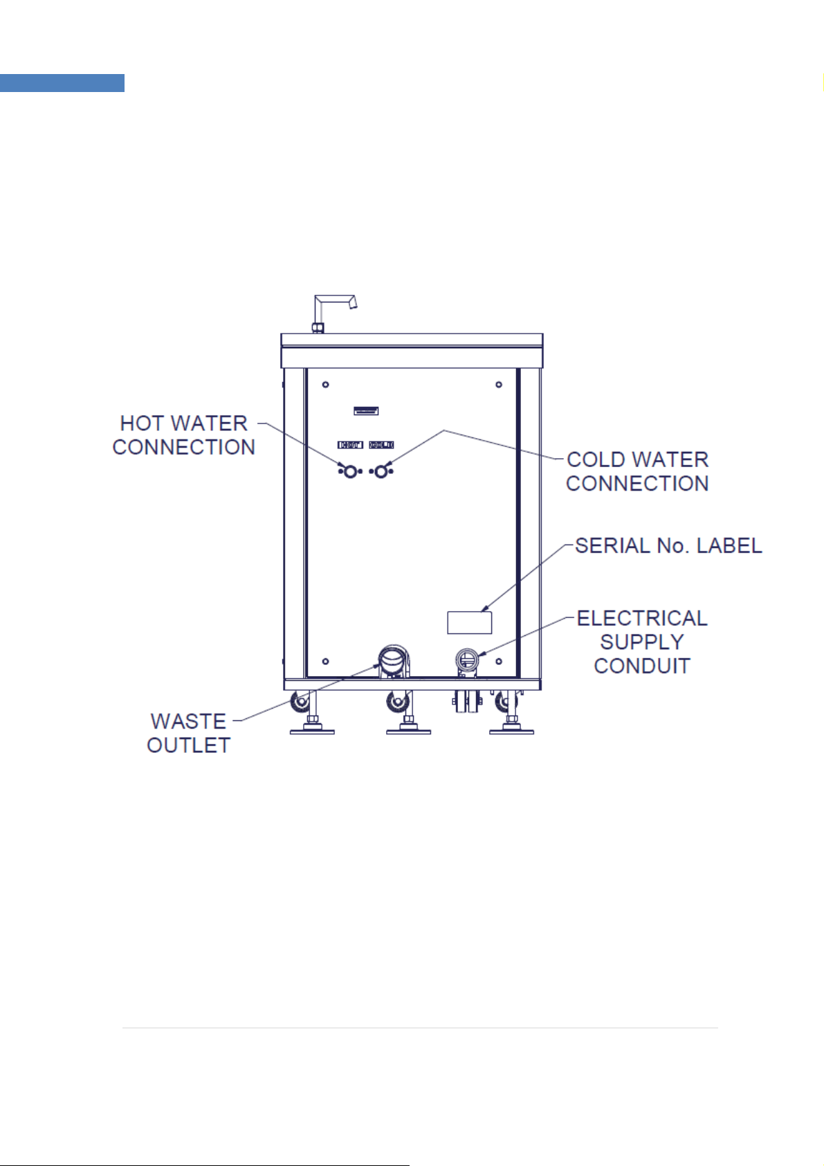
SUPPLY CONNECTIONS –HOT AND COLD WATER INLET SUPPLIES.......................................... 7
WASTE OUTLET CONNECTION............................................................................................. 8
ELECTRICAL CONNECTION .................................................................................................. 9
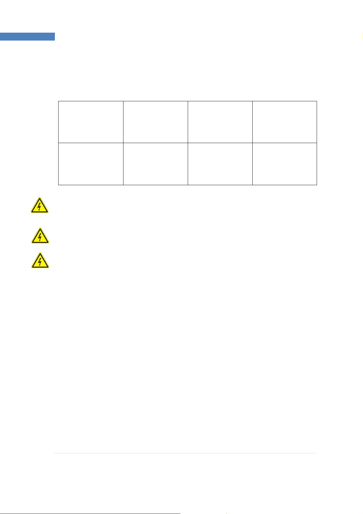
MACHINE RATINGS..........................................................................................................10
TESTING..........................................................................................................................10
OPERATION OF MACHINE................................................................................................. 11
MACHINE RUNNING MODES & INDICATOR LIGHTS.............................................................11
INITIAL OPERATION ......................................................................................................... 12
NORMAL OPERATION ...................................................................................................... 14
RELEASING A JAM............................................................................................................ 14
NOTE.............................................................................................................................. 15
WATER FLOW CONTROL...................................................................................................15
ONGOING MACHINE REQUIREMENTS................................................................................ 15
USAGE............................................................................................................................ 16
CIRCUIT DIAGRAM:.......................................................................................................... 17
PARTS LIST - MACERATOR ................................................................................................ 18
EXPLODED VIEW 1 ........................................................................................................... 19
EXPLODED VIEW 2 ........................................................................................................... 20
EXPLODED VIEW 3 ...........................................................................................................21
EXPLODED VIEW 4 ........................................................................................................... 22
PARTS LIST F79/240 WasteStation Compact....................................................................... 23
SPARES........................................................................................................................... 23
FAULT DIAGNOSIS ........................................................................................................... 24
ORDERING SPARE PARTS.................................................................................................. 25
FURTHER INFORMATION.................................................................................................. 25

3 | P a g e
WasteStation Compact
MACHINE DIMENSIONS

4 | P a g e
WasteStation Compact
View on Rear of Machine Showing
Connections for Services

5 | P a g e
WasteStation Compact
INTRODUCTION
This machine is intended for the processing of food waste matter by maceration under an
automatic water flow, dewatering of the macerated food waste and discharge of the dewatered
food waste into a receptacle. The ‘grey’water will be discharged into the drainage system.
This machine is to be operated by trained personnel only.
MODEL INFORMATION
There is currently one Single Phase version: -
F79/240 with motor (size combined) 2.4kW (3.2HP)
Please read these instructions carefully for trouble-free installation and operation.
Please observe these instructions carefully.
The guarantee applies in this form to installations within the United Kingdom. Contact your
WasteStation supplier first.
ON DELIVERY
Please check the contents against the following list and notify both the Carrier and Supplier within
three days if anything is missing or damaged.
Fully assembled WasteStation with following items loose: -
Release key = 1 off
Feeding Pusher = 1 off
Waste bin = 3 off
Instruction Manual = 1 off
Operating Plaque = 1 off (wall mounted self-adhesive)
GUARANTEE
This machine is guaranteed by IMC for 2 Years (UK warranty only) from the date of its purchase
from IMC, or from one of its stockists, dealers or distributors. The guarantee is limited to the
replacement of faulty parts or products and excludes any consequential loss or expense incurred
by purchasers. Defects, which arise from faulty installation, inadequate maintenance, incorrect use,
and connection to the wrong electricity supply or fair wear and tear, are not covered by the
guarantee.
The guarantee applies in this form to installations within the United Kingdom only.

6 | P a g e
WasteStation Compact
Please observe the following instructions carefully.
INSTALLATION OPTIONS
FOR THE INSTALLER
These Instructions contain important information designed to help the user obtain the maximum
benefit from the investment in an IMC WasteStation Compact.
Please read them carefully before starting work, and consult with the supplier in the event of any
queries.
Be sure to leave this Instruction Manual with the user after the installation of the machine is
complete.
The machine is operated from the wall mounted control box.
SELECTION OF SITE
Select the site of the WasteStation Compact with care so that it is convenient both for the major
source of food waste and for access by machine operators. The machine should be installed as
close to the existing drains as is reasonably practicable.
Install so that the front of the machine with the controls on faces the operator.

7 | P a g e
WasteStation Compact
ORDER OF CONNECTION FOR ALL INSTALLATION OPTIONS
Install in the following sequence:
1Adjust height and level to leave a gap of 100mm between the floor and underside of
machine chassis.
2Reconnect the locknut to the large cable gland on the rear panel, remove side panel for
access.
3 Connect waste outlet to the drains
4 Connect both water supply pipes ensuring correct orientation
5 Connect the electricity supply
6 Test and make any necessary adjustments.
7 Fix the self-adhesive instruction plaque in a prominent position adjacent to machine
W
ARNING –THE MOTOR ON THE DEWATERER MUST ROTATE IN DIRECTION OF ARROW OR SERIOUS
DAMAGE WILL OCCUR TO THE UNIT DURING FOOD PROCESSING
I
F THE PIPE JOINTS ARE NOT CORRECTLY MADE, WATER LEAKAGE MAY OCCUR
1. Move the unit into position and adjust the levelling feet, it is advised that the height of the
machine should be set to give a gap of 100mm underneath the machine to the floor for
cleaning access.
2. Using a spirit level, check that the top of the unit is level in both planes and that it is at the
required height. When correct, tighten all nuts and re-check levels.
3.
Continue with SUPPLY CONNECTION INSTRUCTIONS.
SUPPLY CONNECTIONS –HOT AND COLD WATER INLET SUPPLIES
THE FOLLOWING ARE IMPORTANT INSTALLATION REQUIREMENTS
The plumbing system is to be installed and used in accordance with the requirements of the Water
Supply (Water Fittings) Regulations and Byelaws. The purpose of these regulations is to protect
your drinking water supply from contamination.
The WasteStation Compact is supplied with a cold-water air break, customers are to ensure that
the HOT water supply is compliant and has an approved air break or back flow prevention.
By-laws and Regulations vary by region so it is important to check with the authority having
jurisdiction in your area.
A 15 mm HOT and a 15mm COLD water supply are required on WasteStations, and the connections
should be made to the ¾”‘Washing Machine’style connections on the rear of the machine. The
head of water should not be less than 0.18 bar (1.8m). Use the ‘NEW Supplied Hoses’, Do Not Use
‘Old Hoses’
When fitted with the class A air break hopper and baffle, these machines meet UK water
regulations. The water supply connection is achieved via a storage cistern or mains supply, to which
no other fittings are to be coupled.
The rate of water flow required for normal food waste is 8 -10 litres per minute.

8 | P a g e
WasteStation Compact
WASTE OUTLET CONNECTION
The machines are fitted with a standard 2”waste pipe stub outlet. The size of these outlets must
not be reduced, and the drainpipe should run into 54mm outside diameter pipe work as far as its
junction with the main pipe or outside manhole connection.
The length of run between the machine and the main junction must be kept to a minimum and the
pipe run must have a fall of at least 1 in 7.
It is recommended that a running trap should be fitted, although “P”or “S”type traps can be used.
Do not use bottle traps. Changes of direction should be made by bends rather than elbows and
cleaning eyes should be fitted where possible, in accordance with standard plumbing practice.
Copper pipe and compression fittings should be used, but plastic tubing is acceptable to most
drainage authorities.
IMC WasteStations must have an independent waste pipe, which does not also serve sinks,
dishwashers and similar equipment. It is imperative that the waste pipe from the WasteStation
bypasses any existing in-line grease trap or grease separator that may be present unless said trap
or separator has been specified to suit the output of the WasteStation along with the existing
equipment. Should a grease trap or separator be used solely for the WasteStation, it must be
specified by the supplier to suit the output of the WasteStation. If this outlet is positioned below a
control box, it is important to use fittings, which give at least the minimum 220 mm clearance,
required for service access. Ensure the installation complies with local water regulations.
Every machine is run and tested by IMC before dispatch. The water flow adjustments will require
resetting when installed in the final location. A ‘full bore’service valve should be installed in the
pipe work to each of the water inlets and these should be set fully open to start with, adjusting to
suit during installation. Ensure that water supply demands made by other equipment served by the
same supply pipe do not starve the WasteStation. To avoid this, run the piping in a size larger than
recommended above and reduce at connection point to the machine.

9 | P a g e
WasteStation Compact
ELECTRICAL CONNECTION
All electrical work must be carried out by a qualified electrician and in accordance with the IEE
Codes of Practice. Examine the rating plate located on the rear panel (next to the mains inlet) to
ensure that the characteristics shown are correct for the supply available. The supply cable fitted
is the minimum required for connection to the mains supply. Site conditions may vary with
additional length of cable run, encapsulation in trunking, bunched with other cables etc. Should this
apply, the electrician must alter the cable accordingly.
The WasteStation must be connected to a suitable 16 AMP Single-phase isolator providing at least
3mm separation in all poles.
The mains supply cord - cable colours and cable markings are shown in the table below:
Warning: This appliance must be earthed.
If the supply cord becomes damaged it must be replaced by qualified electrician in order to avoid a
hazard.
Examine the rating plate attached to the machine to ensure that the characteristics shown are
correct for the supply available. The rating plate is located on the rear of the machine.
Sample Rating Plate
Connection
Cable Colour
Cable Marking
Live
Brown
None
Neutral
Blue
None
Earth
Yellow/Green
None

10 | P a g e
WasteStation Compact
MACHINE RATINGS
The table below illustrates typical fuse ratings for an ambient temperature of 25-35°centigrade.
Should the environment temperature be greater than this, de-rate accordingly.
Model
Electricity
Supply Volts-
Phase-Hz
Input kW Fuse Rating
Amps
WasteStation
Compact 240-1-50 2.4 13
The supply to the machine must also be protected by a 30mA RCD (type A,
curve B)
such as IMC part number G35/039, which may be purchased separately from the IMC
Spares Department (contact details shown on final page of this document)
WARNING: This machine must be earthed
WARNING: This machine must not be PAT tested under any circumstances.
It contains an inverter (motor drive) which can be damaged by the test and the test results will be
invalid anyway. This advice is in accordance with standard practice within the industry and is due
to the inductive/capacitive components used within the inverter. If in doubt, please contact IMC
Service Department.
TESTING
Check finally that all supply connections are correctly made and soundly fixed, that nothing has
been left in the grinding chamber, that the rotor is free to rotate (use the release key if necessary)
and that the interlock knob is screwed down (FINGER TIGHT ONLY).
The machine is now ready to operate.

11 | P a g e
WasteStation Compact
OPERATION OF MACHINE
During the operation of the machine certain indicator lights will be illuminated on the front control
box these give an indication of what operation the machine is carrying out.
MACHINE RUNNING MODES & INDICATOR LIGHTS
When the machine is running the button lights on the front of the machine will be constantly lit or
flash, the meaning of this is explained below.
Solid Green Flashing Green No Lights
Machine Running Machine Stopping Machine Stopped
No Warnings
Flashing Blue Solid Red Flashing Red
Machine in Cleaning Mode WARNING! –Bin Not Present WARNING! –Bin Full
Machine Stopped Machine Stopped

12 | P a g e
WasteStation Compact
INITIAL OPERATION
1. Switch on the electricity and water supplies.
2. Ensure that a waste bin is in place in the machine outlet area (a red light will illuminate if
the bin is not in place).
3. Press the green ‘START’button, water should flow immediately, if no water flows within 2 >
3 seconds, press the emergency stop button to stop the machine and check the water supply
connections and ensure that the water supplies are turned on.
4. With the machine running, inspect the waste and water supply piping for leaks. Use a flow
meter to check that the volume of water flowing is correct –refer to WATER SUPPLY
CONNECTION. If adjustments are needed, use a screwdriver to adjust the position of the slot
on the control screw of the service valve. Maximum flow is with the slot in line with the pipe.
5. Undo the front panel of the machine by releasing the black catch on the front panel. Ensure
that the auger within the dewaterer (WastePro II) is rotating in a clockwise direction
(viewed from top and same direction as the arrow on the motor). Replace the front panel
ensuring the catch is secured.
6. Try a small amount of food waste (see poster on next page) to check disposal and
dewatering are working successfully and that there is no internal obstruction in the waste
pipe causing a blockage. Also check that a small amount of waste goes into the waste bin.
7. With the machine running unscrew the baffle interlock knob .The machine will switch itself
off almost immediately. By the time the knob is fully unscrewed and the safety baffle open,
the rotor in the grinding chamber will have completely stopped.
When these checks, tests and adjustments are completed, the IMC WasteStation
Compact is ready for use.
On completion of installation, Commissioning, the appliance is now operational. The person in
charge of this equipment must keep this manual in a safe place and accessible to all operators and
servicing providers. It is the site’s responsibility to ensure adequate training and instruction has
been provided to all associated personnel involved in the operation of the appliance.

13 | P a g e
WasteStation Compact

14 | P a g e
WasteStation Compact
NORMAL OPERATION
1. Ensure that safety baffle is closed and the interlock knob is screwed down fully but lightly.
(Do not overtighten).
2. Press green button to start. This activates the start-up sequence. Allow 20 seconds to fully
complete the start up.
3. Feed waste into the hopper at a slow uniform rate (not too fast), using the feeding pusher if
necessary, briefly allowing each load to clear the macerator before feeding in the next batch.
4. If the macerator stalls or is severely overloaded, it may cause the automatic cut out on the
motor to operate. Once the motor has cooled it can be re-started. Note that stopping the
motor and restarting it reverses the direction of the rotor and can help to relieve an
overload. If the machine remains stalled, see RELEASING A JAM below.
5. If overly wet food goes into the waste bin then the rate of feeding the hopper should be
decreased, and the unit allowed to run with no food for a short while to allow it to flush.
RELEASING A JAM
Food Waste Disposers can jam under overload or if unsuitable materials are placed inside.
IMC machines are designed to withstand this and no damage will normally result, as the
machine will switch itself off. It is necessary to clear the jam as follows:
1. Switch off at the mains isolating switch.
2. Remove the baffle by unscrewing the interlock knob and lifting off.
3. Take out any bulk waste in the disposal chamber. Rubber gloves are recommended
4. If the item, which blocked the disposer, is apparent, remove it.
5. A release wrench is provided with which to turn the rotor if it is jammed. Place the
hexagon socket of the wrench over the hexagonal boss on the centre of the rotor,
or the tines into the rotor and against the cutting edges (depending on the type of
key supplied) lever backwards and forwards until the jammed material releases.
Remove the release wrench and remove the material.
6. Replace the wrench, and ensure that the rotor is totally free throughout its full
rotation.
7. Remove the release wrench
8. Replace the baffle, screwing the interlock knob fully home.
9. Switch on at the mains isolating switch.
10. Press the START button and continue disposal.
In the event of difficulty, call your supplier or the manufacturer for a qualified service
engineer.

15 | P a g e
WasteStation Compact
NOTE
T
he macerator and dewaterer motors, is each protected by a thermal overload relay. If either motor
experiences a problem (e.g. due to a component jam) then the machine will automatically shut
down for a short period (typically 10-15 minutes). At the end of this period the thermal overload
relay will reset itself and the machine will return to normal standby mode ready for operation.
The pump motor is protected by an inverter. If the pump motor experiences a problem, the inverter
will register a fault and the machine will automatically shut down and will remain inoperable until
the problem is rectified and the fault condition on the inverter is cleared. Should this occur, please
contact service personnel for advice.
WATER FLOW CONTROL
When operating the WasteStation, the water flow control should initially be set at its highest
position before turning it down whilst the waste is being processed. The rate of water flow can be
adjusted up or down for each installation to take account of unique factors such as the length of,
and number of bends in, the drainage piping, and the fall of the pipe.
A bucket of warm
(NOT HOT)
, soapy water poured into the FWD’s hopper at the end of each day
will both clean the equipment and help disperse any residual solids in the piping.
ONGOING MACHINE REQUIREMENTS
Daily: Clean down thoroughly after use especially inside the hopper. Unscrew the safety interlock
knob and open the baffle to gain access internally
Cleaning is assisted by the use of a low-pressure spray, an IMC Pre-Rinse Spray or a Reel-
Kleen retractable hose reel.
Place a washing bowl with some warm soapy water in it into the waste bucket area, unclip
the waste chute and with a ‘dishwashing brush’or similar, clean out the inside of the
outfeed chute and also the outfeed area of the dewaterer.
Wipe over the exterior of the machine, including the back areas not normally visible.
Proprietary cleaners may safely be used but avoid particularly aggressive cleaners and neat
bleach solutions.
End each day by pressing the blue ‘Clean’button and allowing the machine to perform its
own dewaterer internal automated cleaning cycle (a bin must be in place to do this)
12 monthly: Check for motor bearing wear by:
-Sound of motor
-Side movement of rotor
-Maintenance Guide MG-016 refers to the Maintenance of the macerator unit.

16 | P a g e
WasteStation Compact
WARNING –BEFORE ATTEMPTING SERVICE WORK ENSURE THAT ELECTRICITY SUPPLY
AND WATER SUPPLY ARE TURNED OFF AT THE MAIN SUPPLY AND WATER STOPCOCK.
USAGE
1THE IMC WASTESTATION COMPACT IS DESIGNED FOR THE DISPOSAL AND
DEWATERING OF FOOD WASTE.
2DO NOT PUT CLING FILM, LIQUID FAT, STRING, CLOTH, PLASTIC, WIRE, GLASS, CORK,
STYROFOAM, BOILING WATER, HOT SOUP, HOT LIQUID, BONES OR METAL OBJECTS
INTO THE MACHINE.
3ALWAYS START THE MACHINE BEFORE PUTTING WASTE INTO IT. INTRODUCING
MIXED WASTE INTO THE MACHINE WILL ENSURE MORE EFFICIENT DISPOSAL THAN
ACCUMULATING AND INTRODUCING WASTE OF A SIMILAR NATURE.
4DO NOT FEED LARGE AMOUNTS ALL AT ONCE, THIS WILL CAUSE BLOCKAGES.
5IF FEEDING LARGE QUANTITIES OF THE SAME FOOD ITEM, i.e. RICE, PASTA, POTATOES
ETC. IT MUST BE FED SLOWLY ALLOWING EACH SMALL BATCH TO PASS THROUGH THE
DEWATERER INTO THE BIN OR BLOCKAGES MAY OCCUR.
6IN NORMAL OPERATION, THE MACHINE SHOULD ALWAYS BE STOPPED BY PRESSING
THE RED BUTTON. THE EMERGENCY STOP BUTTON SHOULD BE RESERVED FOR
GENUINE EMERGENCIES. STOPPING THE MACHINE ROUTINELY USING THE RED
BUTTON WILL CAUSE BLOCKAGES AND DAMAGE WITHIN THE DEWATERER MODULE,
PUMP OR CONNECTING PIPES.
7UNDER NO CIRCUMSTANCES SHOULD THIS MACHINE BE PAT-TESTED, AS DOING SO
MAY CAUSE DAMAGE TO THE INVERTER CONTAINED WITHIN THE CONTROL BOX.
REFER TO PAGE 11 FOR FURTHER INFORMATION.

17 | P a g e
WasteStation Compact
CIRCUIT DIAGRAM:
WASTESTATION
COMPACT 240V-
1PHASE-50Hz
Note that this schematic diagram, plus the full wiring diagram, are both available
on request from the IMC Service Desk (see page 25 for contact information)

18 | P a g e
WasteStation Compact
PARTS LIST - MACERATOR

19 | P a g e
WasteStation Compact
EXPLODED VIEW 1

20 | P a g e
WasteStation Compact
EXPLODED VIEW 2
Table of contents
Other IMC Trash Compactor manuals
Popular Trash Compactor manuals by other brands

GE
GE GE PROFILETM GCG1500L Dimensions and installation information

Krushr
Krushr F86/300 installation manual

Glasdon
Glasdon NEXUS 36G manual

Knape&Vogt
Knape&Vogt USC12-1-35 installation instructions

Whirlpool
Whirlpool GX900QPPB Use and care guide

Cucine Oggi
Cucine Oggi Wesco Pullboy Soft Comfort 1 Assembly instructions