IMEON 3.6 User manual
IMEON3.6
37
Manuel d’installation / Installation manual IMEON 3.6 – Rev A.2
FR
EN
INSTALLATION MANUAL

IMEON3.6
38
FR
EN
Manuel d’installation / Installation manual IMEON 3.6 – Rev A.2
Contents
Important Safety Warning ................................................................................................................39
IMEON 3.6 .........................................................................................................................................40
1- Operation mode............................................................................................................................42
2- Overview of IMEON 3.6 inverter...................................................................................................44
2-1 Connections ................................................................................................................................44
2-2 Compatibility ...............................................................................................................................44
2-3 Standard devices .........................................................................................................................44
3- Installation ....................................................................................................................................45
3-1 Selecting Mounting Location ......................................................................................................45
3-2 Mounting Unit.............................................................................................................................45
3-3 Electrical connection...................................................................................................................47
3-4 PV Module (DC) Connection .......................................................................................................48
3-5 Battery connection......................................................................................................................50
3-6 Load (AC Output) connection .....................................................................................................51
3-7 AC Grid Connection.....................................................................................................................54
4- Communication.............................................................................................................................55
5- Commissioning..............................................................................................................................56
6- Inverter supervision ......................................................................................................................57
6-1 LCD Information ..........................................................................................................................57
6-2 Display by indicator light.............................................................................................................58
6-3 Button definition.........................................................................................................................58
6-4 Query Menu Operation...............................................................................................................59
7- Operation Mode and display ........................................................................................................62
8- Problems and solutions.................................................................................................................65
9- Maintenance & Cleaning...............................................................................................................67
10- Synoptic view ..............................................................................................................................68
11- Wiring diagram............................................................................................................................69
IMEON3.6
39
Manuel d’installation / Installation manual IMEON 3.6 – Rev A.2
FR
EN
Important Safety Warning
BEFORE BEGINNING: Read this guide carefully.
This manual will guide you during your installation and your check before starting the production.
CAUTION: This manual is for qualified staff having high skills and the necessary
experience in inverter installation as well as electricity. It is absolutely forbidden to
proceed to the mounting or dismounting of this kit if you do not have the necessary
skills.
CAUTION: Besides the electric risks on all the installation, the handling of batteries can be
dangerous. Never approach a spark of a battery recently charged. Gloves and safety
glasses are necessary to work near batteries for complete safety.
CAUTION: Authorized service staff should reduce the risk of electrical shock by
disconnecting AC, DC and battery power from the inverter before attempting any
maintenance or cleaning or working on any circuits connected to the inverter. Turning
off controls will not reduce this risk. Internal capacitors may remain charged for 5
minutes after disconnecting all sources of power.
CAUTION: Do not cover IMEON. It is fitted with a heat removal system to avoid any
overheating.
CAUTION: Do not disassemble IMEON yourself. It contains no user-serviceable parts.
Attempt to service IMEON yourself may cause a risk of electrical shock or fire and will
void the warranty from the manufacturer.
CAUTION: To avoid a risk of fire and electric shock, make sure that existing wiring is in
good condition and that the wire is not undersized.
The responsibility of the supplier could not be committed for damage caused by a bad maintenance or
by not respecting the instructions of this manual.

IMEON3.6
40
FR
EN
Manuel d’installation / Installation manual IMEON 3.6 – Rev A.2
IMEON 3.6
For a smart management of your renewable energy installation in self-use.
IMEON is the ideal solution for all your systems of renewable power production (solar energy/ wind
energy / hybrid / …). Thanks to the IMEON, the produced energy is used and directed in an
intelligent way for optimal performance. Its technical conception by specific microprocessor drives
the energy according to the conditions of production and needs in consumptions.
x
3KW multi-use inverter
x
ON GRID / OFF GRID 48V / BACKUP
x
Increase of the yield > 30%
x
Simple and fast installation (Plug&Play)
x
Simplicity of use and exploitation
x
Economic at the purchase (unique product)
x
Great reduction ont the energy invoice
x
Optimized production performances
x
local or remote followed real time
SMART GRID
Thanks to the intelligence of management and the multi energy real-time coupling of the IMEON, the
yield is maximized by choosing the mode of energy presenting the best cost/efficiency ratio: either by
consuming it (self consumption), or by injecting the produced electricity in the electric grid or both at
the same time. Automatic adaptation to the installation’s configuration without necessary parameter
setting, is one of its many smart features.
ECONOMIC
No need for solar charging regulator, for source’s switch or for additional inverters. Thanks to its
intelligent (SMART GRID) functions, IMEON allows to store energy only when it is necessary and, by
improving the efficiency, to lower the price of energy produced by more than 30%. The intelligence of
management and the real-time multi-energy coupling allow to decrease the capacity of the battery and
to improve its life expectancy (number of cycles reduces).
ALL IN ONE
All the features of the IMEON are integrated into a unique case to replace various components:
inverter, charging regulator, sources switch, for: a greater reliability / optimization of the production
organs / reassurance of the persons / a saving of space for the installation / better performance / an
ease in the diagnostic of expertise / a local or distant monitoring, a simple and fast connecting
(Plug&Play) via connector RST and MC4 type.

IMEON3.6
41
Manuel d’installation / Installation manual IMEON 3.6 – Rev A.2
FR
EN
Only one reference for every type of installation
Solar / wind / Hybrid / OFF-GRID / ON-GRID
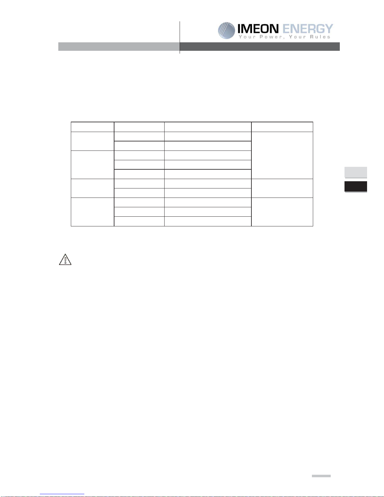
Technical specifications
GRID (ON-GRID & OFF-GRID)
IMEON 3.6
Nominal output power :
3000 W
Maximum output power :
6000W*
AC voltage (input & output) :
230 Vac (±15 %) / 50 Hz (±5 %)
Nominal output current :
13 A
Maximum output current :
26 A*
SOLAR INSTALLATION
Maximum input power :
1500 to 3000 W
Start up voltage :
150 V
MPP voltage range :
120V – 450V (250V – 450V)
Maximum input current :
18 A
Maximum input voltage :
510 V
Solar production use :
Programmable priorities (PV / Storage / Grid)
Maximum efficiency :
DC to AC >95,5% (94,5% EU)
BATTERY & CHARGE
DC voltage :
48 Vdc
Maximum current :
80 A
Maximum battery charging current :
25 A
Type of batteries :
Gel, AGM
Charging curve :
3 phases (Bulk / Absorption / Float)
Voltage compensation :
Dynamic
Battery charge :
Programmable (Threshold / timing tange via AC Grid)
Battery discharge :
Programmable (2 threshold according to grid availibility)
GENERAL
Dimensions (w x h x d) :
440 x 620 x 160
Protection category :
IP 20
Weight :
18 kg
Connectivities :
TL (transformless)
Connectors :
USB / Modbus / Ethernet – IP (option)
Conditions of use
:
Humidity level : 5% to 90 % without condensation
T°C: 0°C to +50°C, degressive power >40°C (15W/°C)
Standards
:
EN 62109-2 / EN 62109-1 / EN 62040-1
DIN V VDE V 0126-1-1 (+VFR2013) / VDE-AR-
N 4105 /
DIN VDE V 0124-100
Warranty
5 years / Extension to 10 years (optional)
* Maximum possible overload power, time-limited, with solar + grid connected. Refer to the installation manual.

IMEON3.6
42
FR
EN
Manuel d’installation / Installation manual IMEON 3.6 – Rev A.2
1- Operation mode
IMEON is an inverter that is able to adapt itself instantaneously according to the weather conditions
and storage. Below are some of its operation modes.
The solar panels
produce enough
energy.
The consumption is
higher than the
energy delivered by
IMEON

IMEON3.6
43
Manuel d’installation / Installation manual IMEON 3.6 – Rev A.2
FR
EN
No consumption
and the battery is
charged
No solar production
and the
consumption is
higher than the
energy delivered by
IMEON
No solar
production and
the consumption
is lower than the
energy delivered
by
IMEON

IMEON3.6
44
FR
EN
Manuel d’installation / Installation manual IMEON 3.6 – Rev A.2
+-
2- Overview of IMEON 3.6 inverter
2-1 Connections
IMEON is an inverter that is composed of a grid input, a solar panels output, a battery input/output and
an output for the 230 Vac production.
2-2 Compatibility
This intelligent hybrid inverter is designed to manage the continuous power of three different sources
of energy, the solar panels, the battery (with or without wind turbine), and the grid electricity, according
to various configurations.
The inverter uses the maximum power point technology (MPPT) to optimize the maximum quantity of
energy supplied by the solar panel. When the solar panels MPPT input is between 120Vdc and
510Vdc, this hybrid inverter can inject the power on the utility and charge battery. This inverter is only
compatible with PV module type of single crystalline and poly crystalline. When the PV input voltage is
lower than 250 Vdc, the deliverable power by the inverter will be reduced.
Some precautions must be realized to make sure that the maximum voltage of open circuit never
exceeds 510 volts. Please note that the maximum voltage will occur in the lowest temperature
planned. You will find detailed information about the influence of the temperature in the data sheet of
the PV module manufacturer.
2-3 Standard devices
The inverter contains the following standard devices:
4- Complete readable data thanks to the graphic design by LCD.
5- To prevent the electric risk, a current transformer is used to watch the difference of current
between L and N. When the difference is bigger than the indicated value in the section
"specification", the inverter will cut its grid (utility) injection.
6- Standard communication port (RS232 / RS485 / USB) : Slot communication card (optional cards)
Grid input
AC Output
Battery
- PV Input
+ PV Input
RS 232
USB
Ground

IMEON3.6
45
Manuel d’installation / Installation manual IMEON 3.6 – Rev A.2
FR
EN
3- Installation
3-1 Selecting Mounting Location
¾ Do not mount the inverter on flammable construction materials.
¾ Mount on a solid surface.
¾ IMEON may possibly be noisy during operation which may be perceived as a nuisance in a
living area.
¾ The temperature may cause a reduction of power due to the excessive heating.
¾ Install the IMEON at eye level in order to allow the LCD display to be read at all times.
¾ Dusty conditions on the unit may impair the performance of this inverter.
¾ Do not switch IMEON on if the temperature or the humidity are out or authorized limits. The
ambient temperature should be between 0°C and 40°C and relative humidity should be
between 5% and 85% to ensure optimal operation.
¾ For proper air circulation to dissipate heat, allow a clearance of approx. 20 cm to the side and
approx. 50 cm above and below the IMEON.
¾ For proper operation of this inverter, please use appropriate cables for grid connection.
¾ The recommended installation position (vertical) is to be adhered to.
¾This inverter is designed with IP20 for indoor applications only.
¾ For the appropriate functioning of this inverter, please use adapted cables cross- section (taking
into account the length of cables, the mode of installation, the impedances, the currents and
tensions).
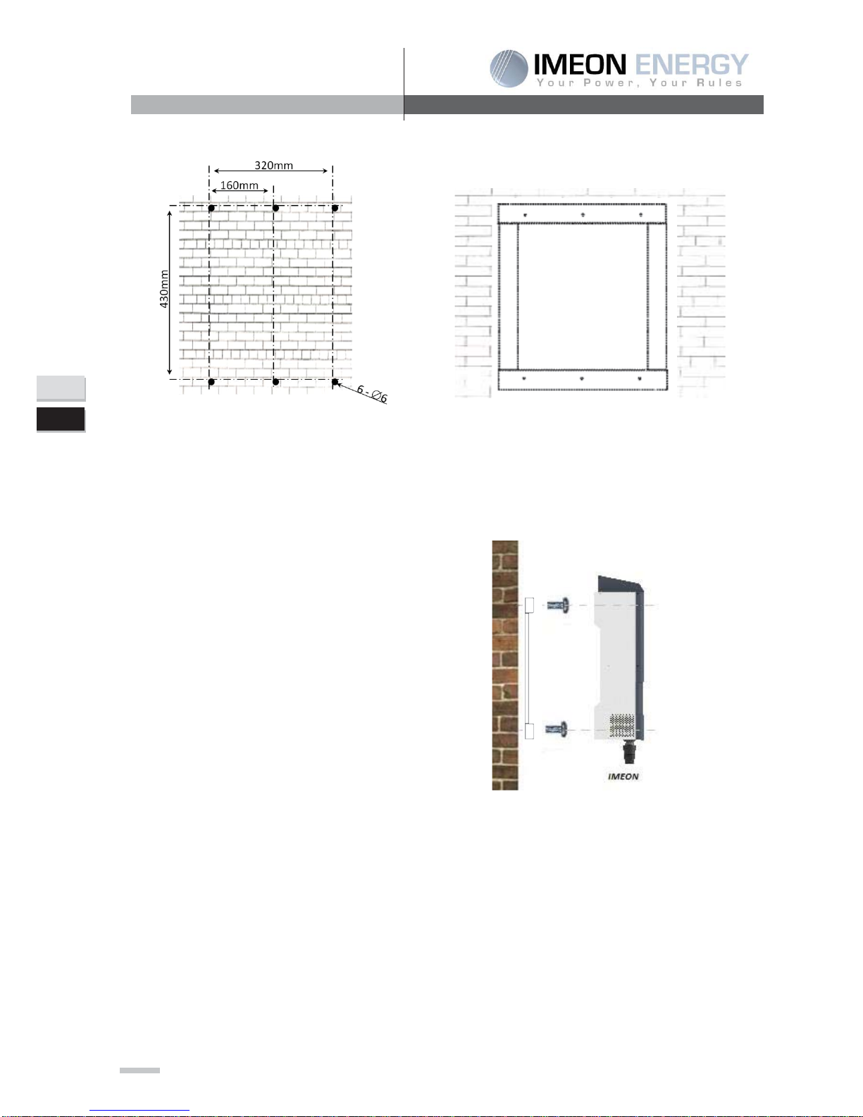
3-2 Mounting Unit
WARNING: This inverter is heavy! Please be carefully when lifting out from the package.
¾ Installation to the wall should be implemented with the proper screws so that the solar inverter
can be easily attached to the wall. After that, the device should be bolted on securely.
Screw to be used :
- 5 à 9 mm
- Ø M5
¾ Choose an appropriate place of support.
WARNING: Suitable for mounting on concrete or other non-combustible surface only ! Take into
account a space of ventilation between the case and the wall.
IMEON3.6
46
FR
EN
Manuel d’installation / Installation manual IMEON 3.6 – Rev A.2
4. Drill four holes in the marked locations
with four screws.
5.
Place the wall plate
against the surface and
fix it with screws M4.
6.
Fit the IMEON on the wall plate and verify
that the inverter is solidly fixed.
Tighten the
two M4 screws to the mounting bracket on
the bottom.
IMEON3.6
47
Manuel d’installation / Installation manual IMEON 3.6 – Rev A.2
FR
EN
3-3 Electrical connection
WARNING: To prevent the risk of electric shock, make sure that the ground cable is correctly
connected to the earth before switching on and using the inverter.
Connectors
Suggestion of cable
PV
PV +
A : + (MC4 type)
10AWG or 6mm2
PV -
A : - (MC4 type)
Grid
L
B : L1 (RST)
N
B : N (RST)
Ground
E (RST)
Battery
BAT +
C : POS +
6AWG or 16mm2
BAT -
C : NEG -
AC output
L
D : L (RST)
10AWG or 6mm2
N
D : N (RST)
Ground
D : Grd (RST)
CAUTION: These values are provided solely for guidance. It is necessary to calculate again the
cable cross section, according to the current and to the used distance.
IMEON3.6
48
FR
EN
Manuel d’installation / Installation manual IMEON 3.6 – Rev A.2
3-4 PV Module (DC) Connection
CAUTION: Before connecting to PV modules, install separately a DC circuit breaker between
inverter and PV modules.
Put protections (circuit breakers, fuses and lightning conductors) according to existing standards.
Before the photovoltaic system is connected, the solar field’s tension must be verified to
make sure that it is correct.
Never open the inverter when the solar field is connected. Disconnect first this one if it’s necessary.
WARNING: Because this inverter is non-isolated, only two types of PV modules are acceptable:
single crystalline and poly crystalline with only Class A-rated. To avoid any malfunction, do not
connect any PV modules with possibility of leakage current to the inverter. For example, non-
grounded PV modules will cause leakage current to the inverter.
Step 1: Check the input voltage of PV array modules, which have to be included in the range of
functioning of IMEON.
CAUTION: Exceeding the maximum input voltage can destroy the unit!! Check the system
before wire connection.
Step 2: Disconnect the circuit breaker
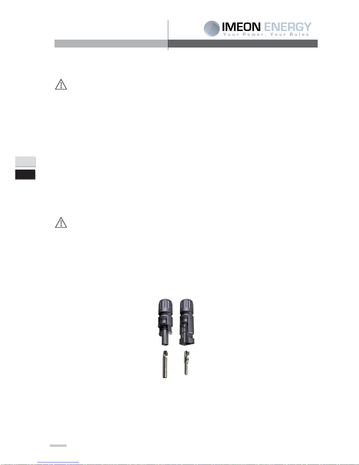
Step 3: Implementation of the supplied connectors
Connecteur DC + Connecteur DC –

IMEON3.6
49
Manuel d’installation / Installation manual IMEON 3.6 – Rev A.2
FR
EN
Step 4: Connect positive pole (+) of connection cable to positive pole (+) of PV input connector.
Connect negative pole (-) of connection cable to negative pole (-) of PV input connector.
Refer to the pictures below :
Step 5: Make sure the wires are safely connected.
CAUTION: It's very important for system safety and efficient operation to use appropriate cable
for PV module connection
1
2
3
4

IMEON3.6
50
FR
EN
Manuel d’installation / Installation manual IMEON 3.6 – Rev A.2
CAUTION: Do NOT touch the inverter to avoid electric shock. When PV modules are exposed
to sunlight, it may generate DC voltage to the inverter.
3-5 Battery connection
CAUTION: Before connecting to batteries, please install separately a DC circuit breaker between
inverter and batteries.
NOTE: Please only use sealed lead acid battery, vented and Gel battery. Please check maximum
charging voltage and current when first using this inverter. If using Lithium iron or Nicd battery,
please consult with installer for the details.
NOTE: Put protections (battery switch, fuses) according to existing standards.
NOTE: It is possible to put inverters in parallel on the same battery (for more information, contact the
installer).
CAUTION: There are risks due to the voltage and the current of the battery. It’s necessary to
protect the borders of connecting.
CAUTION: It's very important for system safety and efficient operation to use appropriate cable.
Step 1: Make sure the nominal voltage of battery is around 48Vdc.
Step 2: Use two battery cables. Remove insulation sleeve 12 mm (a), insert into cable ring terminal
and crimp it for an area of 11 mm on 22 mm then join it into the connector (b).
(a)
(b)
Step 3: Connect battery connector to IMEON in “DC BATTERY” connector.
CAUTION: Batteries must be isolated via the battery switch (OFF position) to avoid any electric
arc which can be irreversible for the IMEON.
b)

IMEON3.6
51
Manuel d’installation / Installation manual IMEON 3.6 – Rev A.2
FR
EN
Step 4: Put the battery switch on “ON” position to connect the batteries to the IMEON.
CAUTION: Do not switch the circuit breaker when the IMEON is under load, it can damage the
inverter.
Batteries (4 x 12V = 48V)
To size correctly the battery capacity, a study must be made.
NOTE: Maximum battery current is 80A. Maximum charging current is 25A.
The charging current has to be between 10% and 20% of the total battery capacity
IMPORTANT:
Before connecting them, verify the voltage and the polarity of the battery.
3-6 Load (AC Output) connection
IMEON3.6
52
FR
EN
Manuel d’installation / Installation manual IMEON 3.6 – Rev A.2
CAUTION: To prevent further supply to the load via the inverter during any mode of operation,
an additional disconnection device should be placed on in the building wiring installation.
Please use protections (circuit breakers, fuses and lightning conductors) according to existing
standards.
CAUTION: It's very important for system safety and efficient operation to use appropriate cable
for AC connection. To reduce risk of injury, please use the proper recommended cable size as
below.
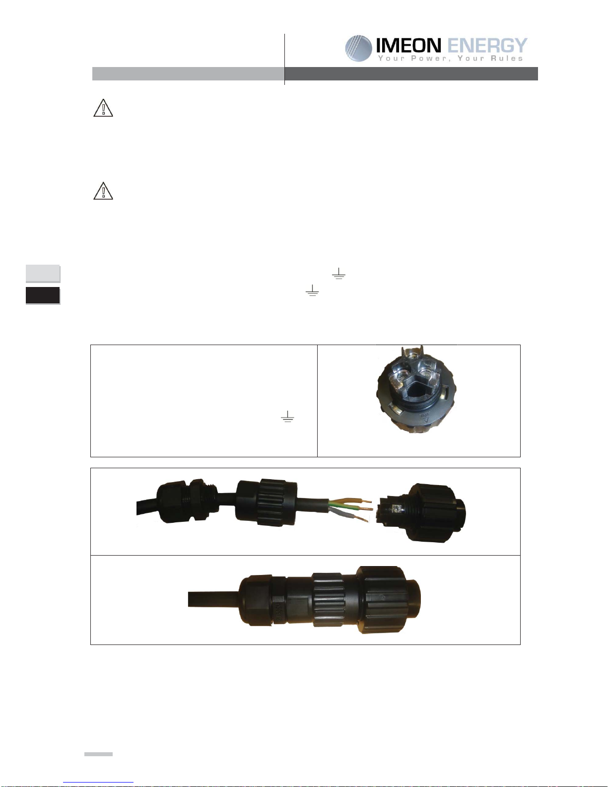
Step 1: Remove insulation sleeve and connect wires according to polarities indicated on terminal
block. Be sure to connect PE protective conductor ( ) first. Respect the connecting of the
neutral (N), of the phase (L) and the ground ( ).
x Connect the phase to the symbol « L »
x Connect the neutral to the symbol « N »
x Connect the ground to the tsymbol «
»
1
2
3

IMEON3.6
53
Manuel d’installation / Installation manual IMEON 3.6 – Rev A.2
FR
EN
Step
2:
Connect the RST
Connector
on the
AC OUTPOUT.
As
the following image
demonstrates .
Step 3: Make sure the wires are securely connected.
CAUTION: At the time of the AC Output connection, make sure that it has no consumption on
the circuit.
NOTE: AC Output cannot be connected in parrallel to another IMEON and cannoot be connected to
the grid.
NOTE: The inverter current (battery + PV) cannot exceed 16A (13A nominal). In the case of grid
outage, make sure not to go over this figure. Otherwise, it is necessary to use a source switch that can
shed load in the case of grid outage (example: Power Switch).
IMEON3.6
54
FR
EN
Manuel d’installation / Installation manual IMEON 3.6 – Rev A.2
3-7 AC Grid Connection
Before connecting to AC utility, please install a separate AC circuit breaker between inverter and AC
utility. This will ensure the inverter can be securely disconnected during maintenance and fully
protected from over current of AC input.
Note: Although this inverter is equipped with a fuse (30A), it is still necessary to install a separate
circuit breaker for safety consideration. Please use protections (circuit breakers,fuses and
lightnin conductors) according to existing standards.
WARNING: It is very important for system safety and efficient operation to use appropriate cable for
grid (utility) connection.
Step 1: Check the grid voltage and frequency with an AC voltmeter. It should be the same to “VAC”
value on the product label. It has to be in the range of functionning of IMEON
Step 2: Turn off the circuit breaker.
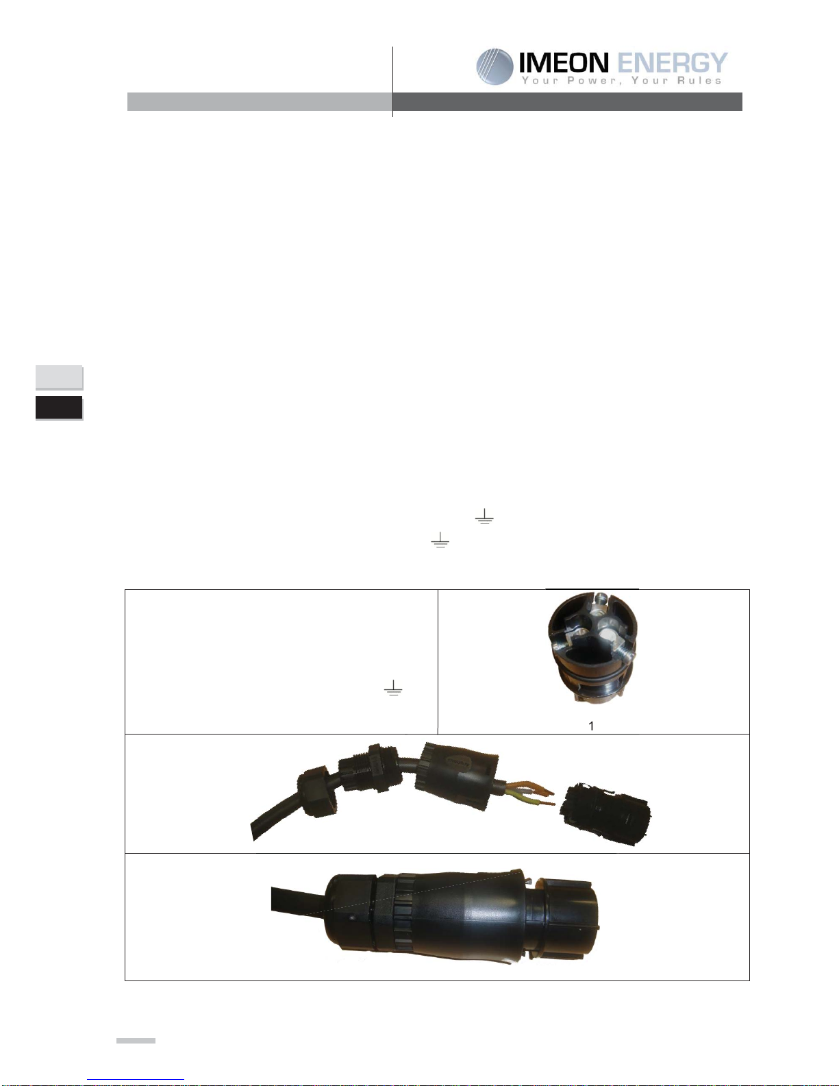
Step 3: Remove insulation sleeve and connect wires according to polarities indicated on terminal
block. Be sure to connect PE protective conductor ( ) first. Respect the connecting of the
neutral (N), of the phase (L) and the ground ( ).
x Connect the phase to the symbol « L »
x Connect the neutral to the symbol « N »
x Connect the ground to the symbol « »
1
2
3
1
2

IMEON3.6
55
Manuel d’installation / Installation manual IMEON 3.6 – Rev A.2
FR
EN
Step
4:
Connect the RST connector on the
input GRID CONNECTION.
As the
following image shows it.
Step 5: Make sure the wires are safely connected.
CAUTION: To prevent risk of electric shock, ensure the ground wire is properly earthed before
operating this hybrid inverter whether the grid is connected or not.
Note: The current injection to the grid from the inverter cannot go over 16A (13A nominal).
4- Communication
The inverter is equipped with RS232 and USB ports and it is also equipped with a slot for alternative
communication interfaces in order to communicate with a PC with corresponding software. This
intelligent slot is suitable to install with Modbus or Ethernet card.

IMEON3.6
56
FR
EN
Manuel d’installation / Installation manual IMEON 3.6 – Rev A.2
5- Commissioning
Verify the continuous Vdc voltage of the solar panels:
¾ Uncover the solar panels and expose them to the full sunlight. The sunlight must be rather
intense to produce the necessary voltage on the inverter.
¾ Measure the Vdc voltage on the open circuit of the solar panels through the positive
terminal C.C(-) and the negative terminal C.C(+). This voltage must be included between
120 V continuous and 510 V continuous to activate the electronics of the inverter.
Verify the Vac voltage :
¾ By using a voltmeter in Vac position, measure the voltage of the open circuit between L
(phase) and N (neutral). Assure that this output voltage is equal to the value of the grid.
Verify the battery voltage :
¾ Assure that the battery voltage is for the nominal value approximately planned for the inverter
(48 Vdc).
¾ Verify the good sizing of the cabling between the inverter and the battery.
CAUTION: Before switching on, verify again all the connectors and all the connectings.
Table of contents
Popular Inverter manuals by other brands


Mastervolt
Mastervolt AC Master 12/2500-230 User and installation manual

GYS
GYS PSW 600 W Translation of the original instructions

Growatt
Growatt MAC 60KTL3-X LV Installation & operation manual

Black & Decker
Black & Decker PI750AB instruction manual

Omnik
Omnik Omniksol-3k-TL2 user manual

Johnson Controls
Johnson Controls York YHFJXH028BAR FX Series installation manual