IMET VTF 500 Guide

VTF500.DOC
63A VERSION A
MI/A/01-95/0
---------------------------------------------------------------------------------------------------------------------------
INSTRUCTION MANUAL, MAINTENANCE AND SPARE-PARTS
---------------------------------------------------------------------------------------------------------------------------
BAND SAWING MACHINE , recommended for cutting metal materials
MODEL : VTF 500
VERSION : SHI-E ( semiautomatic, electro-hydraulic )
/ ESC ( Variable speed band unit )
( the summary of the foreseen marking conditions is on pag.3 )
---------------------------------------------------------------------------------------------------------------------------
IMET S.p.A
Località Tre Fontane-24034 CISANO BERGAMASCO (BG)
Tel. 035 / 787833 Fax. 035 / 787 066
---------------------------------------------------------------------------------------------------------------------------

63B + 63C VERSION A
TECHNICAL ASSISTENCE
We recommend to read carefully the informations here included to install, to use and to maintain correctly
and safely this machine.
Please always refert to this instruction manual in case of need of the assistence service staff and keep it
carefully for all the life of the machine . The reference number is shown on the cover.
GENERAL INDEX
1 - Machine description- applied norms -marking 63 DE
2 - Technical specifications 63EA
3 - Foreseen use and controindications 63FB
4 - Moving and transit 63GA
5 - Installation - minimum requirements 63HA
6 - Fittings assembling 63IA
7 - BAND CHOICE 63ISA
8 - Machine setting for starting 63LA
8.1 - Cooling system "
8.2 - Electrical connection "
8.3 - BAND TENSION "
9 - Starting 63MY
9.1 - Keyboard "
9.2 - Cut end setting "
9.3 - Displayed informations "
9.4 - Controls description 63MA
9.5 - Cutting setting "
9.6 - Semiautomatic cycle "
9.7 - E.S.C working ( Electronic Speed Control ) "
9.8 - Stop/ EMERGENCY STOP "
9.9 - Head rotation for oblique cutting "
9.10-Saw frame inclination "
9.11-Supplementary vice for clamping profiles ( if equipped with it ) "
10 - Adjustments 63NA
10.1-Vice "
10.2 - Band "
10.3 - General working pressure "
10.4 - Cutting speed "
11 - Maintenance "
11.1 - Recurrent maintenance "
11.2 - BAND REPLACEMENT "
11.3 - BAND RUNNING-IN 63NRA
11.4 - Machine running-in 63NRE
12 - Defects identified
12.1 - Machine
12.2 - Band
13 - Working schemes
13.1 - Electrical circuit QE0010B2
13.2 - Hydraulic circuit QE0039A5
14 - Machine noise 63PA
15 - The draining of used / made substances 63RA
16 - Machine demolition 63SA
17 - Guarantee norms
18 - SPARE-PARTS
18.1 - Norms to request the spare-parts 63OA
18.2 - Part drawings RI0020A2+RI0021A4
18.3 - OILS AND LUBRICANTS

28/11/02-\\SERVER\TECNICO\-SNZ\0Sit\hVtf500shie.doc-Scheda Identificazione Codice Padre (mac.sott.etc...)-
3 di 62 pagine.
Pagina n°-
3
63 DE
1 - MACHINE DESCRIPTION, E.C. SAFETY NORMS, SUGGESTIONS FOR THE USE
Semiautomatic, electro-hydraulic band sawing machine with hydraulic movements. Suitable for cutting metal
profiles and solids from 45 deg. right to 45 deg.left.
It is not suitable to cut wood and assimilated materials ( cfr.D.M.89/392, enclosure I, paragraph 2.3
).
The automatic working cycle is usually consisting of : locking of the material, feeding and cutting, tool return
and unlocking of the material.
The operator must make the cutting adjustments , the displacement of the material and the starting. For
making oblique cuts it is also necessary to tilt manually the saw frame from 45 deg. right to 45 deg. left .
The applied safety norms are mentioned in the included compliance declaration.
From the position of the work, in front of the frontal vice, the operator has the possibility to actuate the
controls and to control the precision of the sawing .
In the following paragraphs you will find any informations to use the machine in the best way and for a very
long time.
The following picture sums up all indications necessary for the machine marking:
- identification plate, with the serial number, is fixed on the front right angle - pos. A ;
- the keyboard of the electronic control has a further register number placed on the back shield - pos. B ;
- each motor - pos. C and D, has its own serial number.
1.1 - APPENDIX FOR E.M.C.
The structure of this machine is complying to the protection requirements of the EEC Directives 89/336/EEC,
92/31/EEC and 93/68/EEC in terms of Electromagnetic Compatibility (E.M.C.).
In particular it respects the technical prescriptions of the norms EN 55011 and EN 50082-2, and it is
foreseen to be used in industrial enviroments and not in residential ones.
28/11/02-\\SERVER\TECNICO\-SNZ\0Sit\hVtf500shie.doc-Scheda Identificazione Codice Padre (mac.sott.etc...)-
4 di 62 pagine.
Pagina n°-
4
63 EA
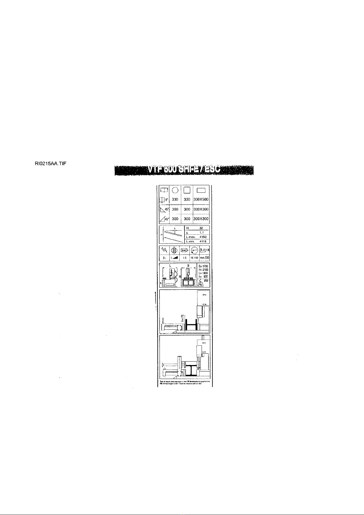
The technical specifications that you will find in the following tables serve to have a general evaluation of the
machine and its performances.
From up to down the tables illustrate :
1) cutting capacity ( maximum possible sizes with the saw frame in vertical position;if the saw frame is low of
5 deg. , the maximum width reduces from 330 mmm to 30 mm).
2) foreseen tool type
3) Type of motors to be used and tool speed; opening vice .
4) exterior sizes and weight of the machine without istalled fittings .
5) profiles cutting without supplementary vice.
6) supplementary vice for clamping profiles .
Other main data are :
Band tensioning = 2200 kg/cmq; jaws height and rear rollers = 170 mm;
work table width = 1200 mm including 5 supporting rollers.
Tank capacity : for the cooling = 30 lit; for the hydraulic oil = 10 lit.

28/11/02-\\SERVER\TECNICO\-SNZ\0Sit\hVtf500shie.doc-Scheda Identificazione Codice Padre (mac.sott.etc...)-
5 di 62 pagine.
Pagina n°-
5
63 FB ( FOR SEMIAUTOMATIC MACHINES )
INSTRUCTIONS FOR USE - SUGGESTIONS FOR THE OWNER AND THE OPERATOR
This machine is designed and manufactured so as to be safely used by the operator, provided that it is
properly operated . No protections will ever suffice if the operator does not work with due caution, does not
make sure that the machine is in top operating conditions and does not follow the instructions below.
The machine can make some automatic work cycles, but at the end of each one the operator is necessary
to replace the cut workpiece and to change the cutting conditions. Therefore sometimes the machine must
be used with manual cycle and sometimes with automatic cycle ( so the operator is not indispensable ).
You must remember that the machine is designed to CUT METALS with a sharp tool, and you are
responsible to see that it is operated in a SAFE and CORRECT manner.
You must :
1. make sure that the machine is properly installed and electrical installation is proper.
2. be sure you are familiar with all operating, safety, and applications information before
operating this machine.
3. see that all who operate this machine are properly trained and fully aware of all safety
practices.
4. not expose yourself or other people to any risk.
5. insist on proper personal protective equipment and practices.
6. maintain all factory installed SAFETY DEVICES and make sure that these are never
removed or altered or restricted in any way.
7. insure that the operator has a safe and orderly work area with adequate light and operating
room.
8. be certain that your machinery receives responsible and competent maintenance and that
your machinery is inspected on a regular basis.
9. never mount tools with different features from those for which the machine is designed for.
10.never use this machine to cut workpieces larger than the stated capacity.
11.keep cutting area clear of tools or other loose objects.
12.never operate machine unless all guards are in place.
13.NEVER WEAR loose clothing, long sleeves, large gloves, jewellery, or any other
items that may be caught. Confine long hair.
14.always disconnect power at source when performing maintenance or making
adjustments.
15.never insert hands or arms into or near cutting area while machine is running.
16.properly clamp the workpiece in the vice and never hold it with your hands.
17.adequately support stock on both sides of the machine to prevent falling.
18.when cutting very short pieces, make sure they do not jam into the blade.
19.if the blade becomes jammed, turn immediately off the emergency locking button, then
replace the cutting unit on CUTTING START position. If it is not possible open the vice and move the
piece check that the blade or the teeth are not broken, if so replace it.
20 never change the working conditions during the cutting, change them for those precisely indicated only
( for example speed changing with inverter ESC ).
21.not move the machine while cutting and avoid its instability.
22. wear the personal safety equipment, if required for a safe operation.
ALWAYS OPERATE MACHINE SAFELY, USING COMMON SENSE AND ALERTNESS .

28/11/02-\\SERVER\TECNICO\-SNZ\0Sit\hVtf500shie.doc-Scheda Identificazione Codice Padre (mac.sott.etc...)-
6 di 62 pagine.
Pagina n°-
6

28/11/02-\\SERVER\TECNICO\-SNZ\0Sit\hVtf500shie.doc-Scheda Identificazione Codice Padre (mac.sott.etc...)-
7 di 62 pagine.
Pagina n°-
7
63GA
MOVING AND TRANSIT
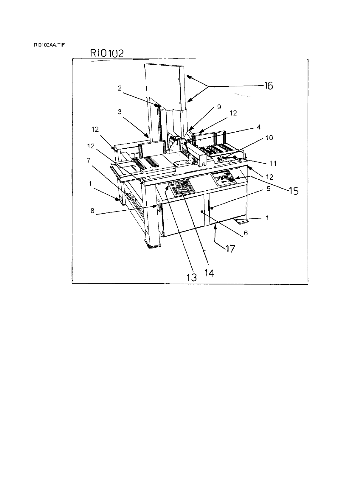
In case the machine is in a protection cage ,a fter unpacking , unscrew the screws that jut out from the low
side of the 4 little supporting feet-pos.1/dr.RI0102 ( they serve to avoid the sliding of the machine during the
transit ).
Use the 4 plates fixed to the angles of the base to hook the ends of the tools suitable to sling the
machine.The weight is shown on the identification number plate and is also reported in the technical data of
the manual.
Make sure that lifting tools are proper for the weight and that the moving is correctly made without
unbalancing the machine.
Please ONLY USE the fastening points placed on the floor stand , do not hook the saw frame or the work
table.

28/11/02-\\SERVER\TECNICO\-SNZ\0Sit\hVtf500shie.doc-Scheda Identificazione Codice Padre (mac.sott.etc...)-
8 di 62 pagine.
Pagina n°-
8
63 H$
- INSTALLATION
The machine can work according to the parameters provided by the manufacturer if it is rightly installed and
the minimum requirements are observed, as follows :
- Machine must be used indoor and with temperatures from +5 to + 40 ° C.
- The relative humidity of the environment must not go over 95%.
- The nominal value of the voltage of electric energy must be between + - 10 and the frequency of the
nominal
value must be between + - 2%.
The floor of the building must be good leveled and it must have a good capacity too.
Floor space, distances and sources of energy are indicated in the following drawing.
The work table must be leveled: by using the screws + nuts put in the little feet holes, it is also possible to fix
the machine on the floor when necessary (for example when there are the connected features).
To grant the return of the coolant that goes onto the bars to be cut, we suggest you: level the work-table with
about 5 mm height each meters lenght to the unload side ( right side).
The enclosed electrical and hydraulic diagrams reproduce the necessary details to arrange the connections
that must be forseen for a requested power of 3 KW.
At the top of the supplying cables it is necessary to set up a sectionalizing device provided with a
protection particularly if it is equipped with the external VOLTAGE TRANSFORMER.
PROTEZIONE DIFFERENZIALE per i modelli dotati di variatore elettronico di velocità ( ESC )
Per inserire la protezione differenziale sulla linea di alimentazione è necessario utilizzare interruttori
con soglia di intervento sulla dispersione della corrente non inferiore a 300 mA ( consigliabile la
taglia 0.3 mA o superiore), eventulmente con la possibilità di regolazione del tempo (0>1.5 sec).
This machine has been foreseen for industrial and not for household use. In the event that should be
electromagnetic interferences the user is responsable for solving the problem together with the technical
assistance of the manufacturer. Before installing the machine the user must take into account possible
electromagnetic problems of the working area. In particular we suggest to install the plant away from:
- signalling, control and telephone cables;
- radiotelevision transmitters and receivers;
- computers or controlling and measuring instruments;
- safety and protection devices.

28/11/02-\\SERVER\TECNICO\-SNZ\0Sit\hVtf500shie.doc-Scheda Identificazione Codice Padre (mac.sott.etc...)-
9 di 62 pagine.
Pagina n°-
9
63 IA
FITTINGS ASSEMBLING
The installation informations are supplied together to the same fitting, but we hereunder include a little
working description.
Supplementary vice for clamping profiles - Its use is clarified by the drawings of the paragraph " Technical
Specifications " . Maximum material size that can be clamped : height 500 mm, width 300 mm.
Loading / unmloading roller table- To rightly install these fittings , first of all it is necessary to level and to
adhere the machine.
Level the loading roller table to the same level of the work table and the rear supporting jaws to line up them
by beginning to that nearest the machine. For the longest workpieces adhere the pedestals on the floor and
recycle the coolant transported by the workpieces that have to be cut.
Roller to lift the workpiece up with manual feeder - fixed between the machine and the loading roller table, it
makes easy the displacement of the big size workpieces that must be placed for the cutting.
Food pedal - connected to the switch fixed inside the right door , when driving , it starts a cicle.

28/11/02-\\SERVER\TECNICO\-SNZ\0Sit\hVtf500shie.doc-Scheda Identificazione Codice Padre (mac.sott.etc...)-
10 di 62 pagine.
Pagina n°-
10
63 ISA
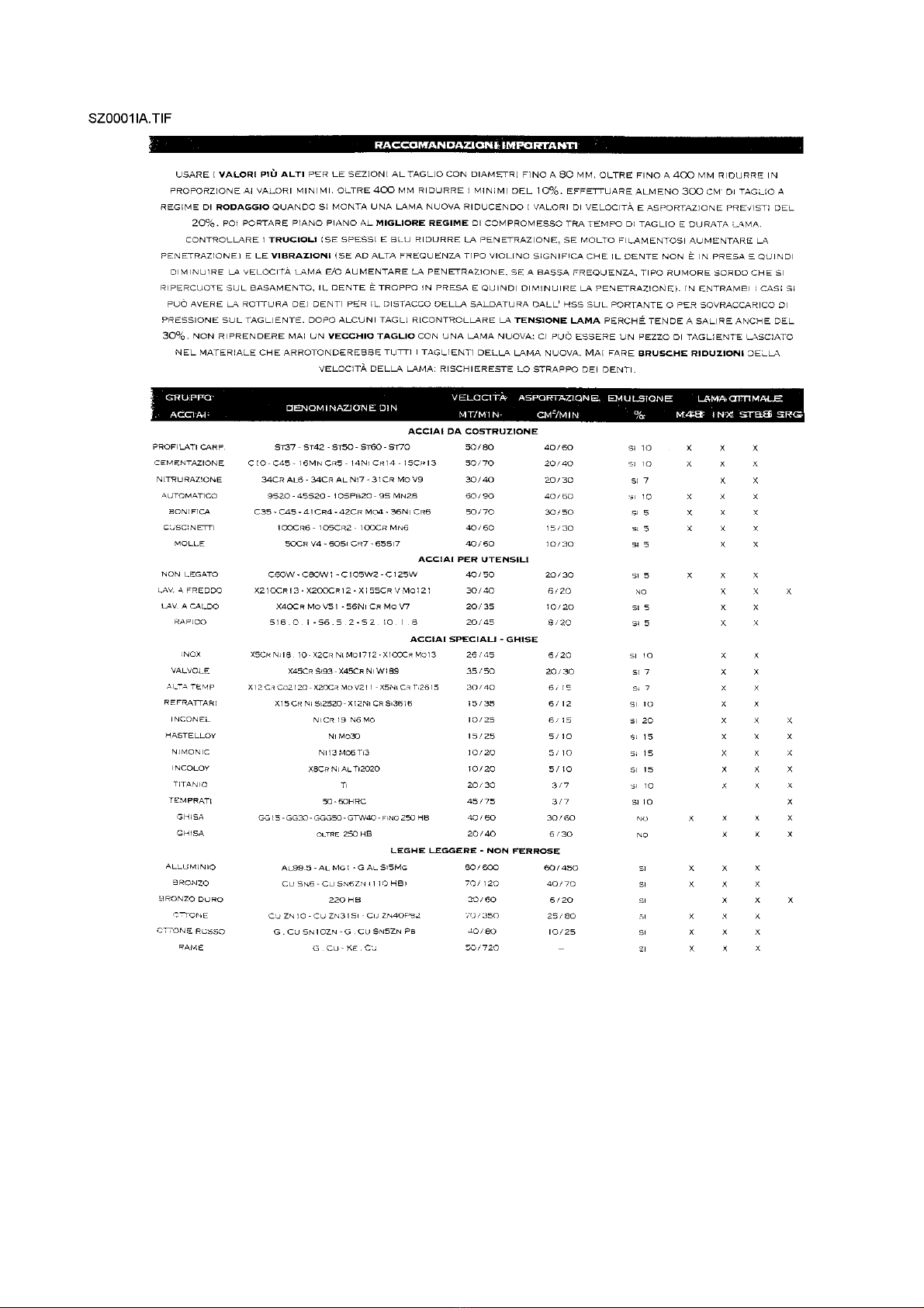
BAND CHOICE
In this paragraph we recommend the type of cutting band in accordance with the material to use . To get the
best performance from this machine it is necessary to undestand the right use and the limits of the used
tools .
The band to use must have the following sizes ( in mm. ) :
maximum lenght = 4150
minimum lenght = 4115
total height = 32 ( or 1 inch and 1/4 " )
thickness = 1,10
It is also important the band material , it is usually used the bi-metal band type in the different endurance
quality .
The standard types are named M2, M48, M42, M51.
The endurance of the teeth increases , and also the fragility, when going from the material M2 to M51.
For making a right cut it is also necessary to choose the pitch ( t ) or the number of the teeth per inch (z).
Usually the band must have the toothing as follows :
- close toothing - to cut thin materials, tubular and profiles.
- thin toothing- to cut solid materials or pieces that need a long band ( for example . the central part of a
profile " U " ), or softer materials as aluminium, copper, soft bronze.
By choosing the right one you can avoid a lot of working errors and you can get a good band penetration
and the necessary space for the chips.
If you cut some pieces at the same time, you must consider them as only one piece by considering the
global size.
The included table supply you the informations for a right choice, the same one can also be updated or
changed by the user according to his personal experiences.
Even if there are toothings with constant pitch , the most of the band sawing machines allow the use of band
with variable pitch toothing - groups of teeth with different pitch between them- that reduce vibrations and
noice, by getting better the finishing and the capacity of removal . This is the reason for which we give you
only the data concerning this kind of toothing..
28/11/02-\\SERVER\TECNICO\-SNZ\0Sit\hVtf500shie.doc-Scheda Identificazione Codice Padre (mac.sott.etc...)-
11 di 62 pagine.
Pagina n°-
11

28/11/02-\\SERVER\TECNICO\-SNZ\0Sit\hVtf500shie.doc-Scheda Identificazione Codice Padre (mac.sott.etc...)-
12 di 62 pagine.
Pagina n°-
12
63LA
8 - MACHINE SETTING FOR STARTING
Verify that machine has not clear damages or faults and check upon the standard equipment that includes
the tools, fittings to do some adjustments, using and maintenance handbook .
In case the machine is supplied with additional equipment make sure that it is adaptable to the machine.
Point in good time the possible damages or faults to the reseller or to the service staff before starting
machine( for ex. rust on the metallic parts, dinges on the sheets, and so on... ).
Remove the lock flask-pos.2 and 3/dr.RI0101- between the saw frame and the base , and bring it again the
screws in their seat. Remove the protective substances from the surfaces, used to keep the machine during
the moving and transit, by cleaning them with a non-filamentous cloth or paper and please check that there
is no rust in the metallic parts.
In case of using compressed air jet always wear proper eye protection.
Open the base doors-pos.5 and 6/dr.RI RI0102 ( the keys are fixed at the vice feeding cables) Take away
the chip pan tank -pos.7/dr.RI0102 - by unhooking it from the guides then remove the possible dirty that can
obstruct the passage of the coolant.
The parts in motion ( band guides, trolleys, pivots, bearing support, bearing disc and so on ) are already
lubricated, the reducer gear holds the exact quantity of oil necessary to the operation ( lubrication FOR-LIFE
).
Hydraulic system is ready to start.
8.1 - COOLING SYSTEM
Prepare the cooling mixing the cutting oil and water ( the tank holds about 30 litres ) in proportion 1/10, 1/15
or according to the instructions of product supplier . After taking the chip pan tank away , pour out the
cooling in the tank or directly on the work table - In this case keep attention that chip pan tank and the tank
are correctly placed .
8.2 - ELECTRICAL CONNECTION
Verify that voltage and power frequency are compatible with numbers reported in the technical data plate (
placed on the right side of the floor stand ) difference over 10% causes some working unevenness more or
less manifested. This operation must be made by authorized , operators ( for ex. by an electrician ) .
Connect an electric cable ( four-polar 4 mmq of section, made according to CEI 20-22 ) to the terminals
marked R, S, T, PE placed on the right, inside the door-pos.6/dr.RI0102-. Mount a plug proper to the wall
socket used in the place where the machine must be installed.
The pashing performed by the manufacturer allows to get a right rotation of all motors by connecting the
wires in the following order L1=R, L2=S, L3=T, anyhow check as follows : ( close the coverband carters in
the tight way ) .
a) in case of EMERGENCY the button is on , turn it off and turn it 1/4 of turning in the marked direction -
pos.1/drawing RI0055-
b) turn on the main switch-pos.8/drawing RI0102- , some leds flash on the control panel -pos. drawing
RI0055- and the display shows some numbers and/or figures.
c) be sure that pressure gauge of hydraulic installation-pos.1/drawing RI0085 , accessible from the door-
pos.5/dr.RI0102 , shows a pressure of about 16/20 BAR.
d) if does not happen in the first 10 seconds turnf off the machine by switching off the general switch and
check the connection to the line ( throw off the feeding plug , reverse the connection of two of the wires of
line connection , excluding the green / yellow cable of grounding and start again from point a) .
e) Be sure that coolant is sucked in by the tank and arrives in the cutting area. ( only if pump recycling is
working ).
f) Stop the working by pushing the main switch-pos.8/dr.RI0102- . If it is supplied with the external
VOLTAGE TRANSFER , place it in the right way and far from the material loading/unloading area.
8.3 - BAND TENSIONING
The machine is equipped with an untensioned band and the starting of the motor is impossible if right force
of tension has not been opened up before. Therefore, let the saw frame on cutting position at 0 deg., open

28/11/02-\\SERVER\TECNICO\-SNZ\0Sit\hVtf500shie.doc-Scheda Identificazione Codice Padre (mac.sott.etc...)-
13 di 62 pagine.
Pagina n°-
13
the rear protection -pos.2/dr.RI0103- by loosing the side screw, unhook the locks of the coverband guard
protection -pos.3/dr.RI0103- and open it to be sure that the band ( " or blade " ) is against the pulley and it
is correctly put in the band guides head , specially the up pulley .
If necessary loosen a little the screw of the band stretcher-pos.4/dr.RI0103, to place again the band , then
close the both guard protections by locking the corresponding fixing parts.
Push the main switch -pos.8/dr.RI0102-, wait for some seconds that the panel - drawing RI0055- stabilizes
its workings, then push many times the pushbutton MODE -pos.10/dr.RI0055- until the LED light marked
with the "band" symbol -pos.6/dr.RI0055- is on.
If the LED flashes , it means that the band is not tensioned : screw the screw of the band adjuster -
pos.4/dr.RI0103- by using the proper spanner , until the LED will be continuinghly
flashing.
The procedure to change the blade after a change of pitch, wear and tear and break is the same one of the
above described procedure .In this case it will be necessary a careful cleaning of all points of connection
with the band.
In the following paragraph you will find the full controls list .

28/11/02-\\SERVER\TECNICO\-SNZ\0Sit\hVtf500shie.doc-Scheda Identificazione Codice Padre (mac.sott.etc...)-
14 di 62 pagine.
Pagina n°-
14
28/11/02-\\SERVER\TECNICO\-SNZ\0Sit\hVtf500shie.doc-Scheda Identificazione Codice Padre (mac.sott.etc...)-
15 di 62 pagine.
Pagina n°-
15

28/11/02-\\SERVER\TECNICO\-SNZ\0Sit\hVtf500shie.doc-Scheda Identificazione Codice Padre (mac.sott.etc...)-
16 di 62 pagine.
Pagina n°-
16
63MY
9 - SYSTEM SWITCHING ON
When you switch the system on, the keyboard displays the loading of the set up data
from the permanent memory "Eeprom" and the release software code. Then, for
about 2 seconds, it displays the identification machine code number .
For going on it is necessary to push the button “Close the vice”- pos. 19 / dr. RIOO55 - that activates
the oil pump - in the hydraulic models -
Please note that in some previous models the starting could be activated by pushing any other button.
If you push other buttons the display shows the error message: ER0034.
If you do not push any other button in 10 minutes, the electronic control deactivates the motor of the
oil unit (if the machine is hydralic). For starting up the system push again the button “Close the vice”
- the display shows for an instant a series of led lights-.
After this operation the system is ready to work.
The led lights on the function keys show the operative condition of the
machine . A series of led lights give information regarding the piece counter, hours counter and so on.
Sometimes after switching the machine on or after caused anomalies, the keyboard
display error codes ( for ex.the band is not tensioned during the transit ).Please refer to the enclosed error
codes list. Push any key to cancel such errors after eliminating the anomaly.
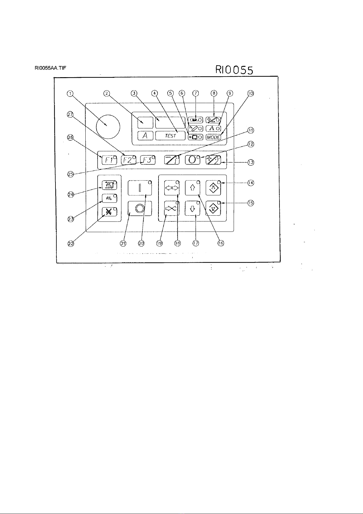
9.1 - KEYBOARD = Buttons description and use, see drawing RI0055.
Pushing the buttons FEED-BACK made with polyester support and IP65 protection,
you schedule any machine operation, including the position of cutting unit :
BACKWARD (16) push it to move the cutting unit away from the workpiece till the maximum programmed
point.The corresponding led light shows that the tool is moving.
FORWARD (17) push it to move the tool away from the workpiece till the minimum programmed point . The
corresponding led light shows that the tool is moving.
CUT START SETTING (14) The led light usually shows the cutting unit position as regards to the stroke
limits ( light flashing =in limit; led light unflashing = out of limit ).
CUT END SETTING (15) as for the key 14 , the led light usually shows the cutting unit position as regards to
the stroke limits.
OPEN VICE (18) push it to open the vice then the led light flashes ( ex. when the cycle starts with open vice,
the vice will open again at the end of the cycle ).
CLOSE VICE (19) push it to close the vice. The same as above, that is, as for the
open vice.
CYCLE START(20) to start a semiautomatic cutting cycle. This intervention can be
no longer operative ( ex. when connecting the foot pedal ). The led light flashing indicates that machine is
working.
CYCLE STOP (21) it allows to stop the semiautomatic cutting cycle at any time and to push
the other keys.
FUNCTION 1 (26) when led light flashing , it allows the stroke return of the tool when the tool is in operation
; if led light is unflashing the tool is out of operation.
FUNCTION 2 (27) It does not work in this model because there is not the approaching phase.
FUNCTION 3 (25) if led light flashing, it finishes the semiautomatic cutting cycle at the end
of the cut .
TOOL SPEED 1 (11) if you push it when the motor is out of operation, it pre-select the lower cutting speed;
if you push it with the tool in motion it determines a speed reduction ( only for machines equipped with
inverter = ESC ) . Led light flashing means that the pre-selection has been made .
TOOL SPEED 0 (12) if you push it when the motor is out of operation , it pre-selects the speed 0 ( motor not
operating ) ; For reasons of security when machine is working the function is not operative.
Led light flashing indicates that pre-selection has been made.
TOOL SPEED 2 (13) by pushing it when machine is out of operation , it pre-selects the highest speed ; by
pushing it when the tool is in motion , it determines a speed increase ( only for machines equipped with
inverter = ESC ). Led light flashing indicates that pre-selection has been made.

28/11/02-\\SERVER\TECNICO\-SNZ\0Sit\hVtf500shie.doc-Scheda Identificazione Codice Padre (mac.sott.etc...)-
17 di 62 pagine.
Pagina n°-
17
COOLANT ON IN SEMIAUTOMATIC CYCLE (24) when led light flashing the coolant pump is on only during
the semiautomatic cutting cycle.
COOLANT ON (23) the coolant pump is always on, for example washing spraygun can be
used to clean the machine.
COOLANT OFF (22) the coolant pump is always off, for example for dry cutting or in
programming machine phase .
3. CUTTING LIMITS PROGRAMMING
It is not necessary a limits programming because the machine automatically adjust the cutting lenght to the
workpiece size clamped into the vice.
9.3.1 DISPLAY INFORMATIONS = mode function
By the key MODE (10) you can see a series of data concerning the machine working .By pushing
sometimes this key , some led light flash in succession and the display shows the demanded value ; Such
data are the following :
CUTTING CYCLE TIME = led light (5) flashing. Display is in seconds "S" or in
minutes "M" or in hours " "
TOOL LIFE ( HOURS OF WORKING OF THE BAND MOTOR ) led light (6) is flashing.
Display as above . For band saw maschines this led light flashing indicates that there is no band tension.
NUMBER OF CUT PIECES = Led light (7) is flashing . Progressive display of numbers
from 1 to 9999 , after which the points appear by side the numbers, that is from 1.
to 9.9.9.9.
CUTTING SPEED PREVIOUSLY SET = led light (8) is flashing . In meters/minutes
for band ; r.p.m. for circular blades and discs.
MAXIMUM CURRENT LOAD OF THE MOTOR = led light (9) is flashing . Maximum
current load in Amp. pointed out in semiautomatic cycle.
All these parameters can be zero-set by the key sequence (4)+(10) by pushing them together, while the
correspondig light is on.
The display (2) constantly shows the electric motor absortion in ampere and
also displays (3) the informative MESSAGES.
9.3.2 - DISPLAY INFORMATIONS = Error codes ( DIAGNOSTICS )
The machine is equipped with diagnostics data and it allows to find the working
anomalies of the machine and to show them to the worker by the error codes as
follows :
ER0001 error in the configuration EEPROM
ER0002 error in the data checksum in EEPROM 1st. locking
ER0003 error in the data checksum in EEPROM 2nd. locking
ER0004 error in the data checksum in EEPROM 3rd. locking
ER0005 error in the saved data in the permanent memory
ER0020 emergency active
ER0021 motor overload protections active
ER0022 open protection guard active
ER0023 broken band entry active
ER0024 machine pressure entry active
ER0025 indication of locked inverter
ER0026 anomalous motor absortion
ER0027 incorrect tool position to start cutting cycle
ER0028 vice entry active
ER0029 unlocking active
ER0030 bar end not effective in automatic cycle
ER0031 carriage not in correct position to start the automatic cycle
ER0032 open feeder vice
ER0033 piece counter selected on 0 for automatic cycle
ER9999 overflow in the machine timers ( it is necessary to switch the system off
and then on ).
28/11/02-\\SERVER\TECNICO\-SNZ\0Sit\hVtf500shie.doc-Scheda Identificazione Codice Padre (mac.sott.etc...)-
18 di 62 pagine.
Pagina n°-
18
Remove the causes of the anomaly and push any key to cancel the display code.

28/11/02-\\SERVER\TECNICO\-SNZ\0Sit\hVtf500shie.doc-Scheda Identificazione Codice Padre (mac.sott.etc...)-
19 di 62 pagine.
Pagina n°-
19
63 MA
9.4 - CONTROL DEVICES DESCRIPTION
The sectionalising device of the outer energy is :
On the left side of the control panel there is the main switch with interlocking attachment, pos-8/dr.RI0102
The control panel , drawing RI0102, placed in front of the operator includes the following :
1 - Main switch with interlocking attachment with thermo-magnetic overload protection of the all installation,
with releasing device for drop of current.-pos.8-.
2 - Emergency device ; it locks any electrical devices when connecting. To restore it, wheel the button 1/4 of
turning-pos.13-.
3- Control panel with display ( see paragraph KEYBOARD )
4 - Hydraulic regulator of cutting speed-pos.15-.
Other devices are placed in other same accessible parts.
5 - Main pressure regulator of the hydraulic installation -pos.5/dr.RI0085-
6- Manual opening/closing of front vice-pos.4/dr.RI0102-
7 - Unlocking/locking of turn saw frame for oblique cuts-pos.10/RI0102; read these cuts at the back grades-
pos.9/dr.RI0102-.
8 - Tap/taps of cooling circuit -pos.5/dr.RI0103- to proportion the liquid on the higher blade guide head , as
well as the main tap assembled on the recycle pump.
9 - Unlocking / locking of the higher sliding blade guide shaft -pos.16/dr.RI0102-.
10-Unlocking of the rapid stops for oblique cuts -pos.11/dr.RI0102 -.
11-Wall socket for synchronism with external gear -pos.17/dr.RI0102-.
12- Tension screw of the band -pos.2/dr.RI0102-.
9.5 - CUTTING SETTING
The assembled band allows the cutting of different material section , thanks to the variable pitch teeth ( little
teeth alternating biger teeth ) , but it is necessary to have the most proper band for the workpiece to get the
best of the machine.
Therefore please refer to the paragraph BAND CHOICE for a right use.
Put the work piece you have to cut into the vice by keeping a shake of 4/5 mm between the piece and the
jaws, necessary for the working of the automatic closing, then place it a little back as regards to the cutting
line.
Be sure that the handle -pos.10/dr.RI0102- blocks the rotation of the saw frame.
Push the main switch-pos.8/dr.RI0102-, restore the emergency device in case it is disconnected -
po.s13/dr.RI0102- , push the button OPEN ARROWS -pos.19/dr.RI0055 to close the vice and be sure that
the piece is correctly clamped in the jaws. If the manual closing of the lever -pos.14/dr.RI0102- is not
enough, the hydraulic cylinder of the vice slides behind and the cycle cannot go on.
Place the higher blade guide shaft so that during the cutting movement it does not knock against the
workpiece or the jaws, then lock it with the levers -pos.16/dr.RI0102-.
Wheel the speed regulator -pos.15/dr.RI0102- at 1 and push the button I -pos.20/dr.RI0055- START
CYCLE ; whatever the cycle may be stated, the machine makes the following :
Blade motor starting, slow cutting feeding, blade stop ( it can be excluded ), rapid return ( it can be excluded
) .
The piece approaching is excluded. The working stroke is automatically determined on the basis of the vice
opening, by further reducing the not productive working cycle
The choice of the most suitable cycle ( F1, F2, F3, coolant off ....... ) must be according to the working needs
.
Please refer to the paragraphs PANEL and POSITIONS PROGRAMMING OF CUTTING SAW FRAME.
9.6 - SEMIAUTOMATIC CYCLE
Set the material so that it goes over the cutting line, then lock it; select the blade speed, the functions, the
cooling distribution and start the cycle by pushing the button START CYCLE pos.20/dr.RI0055-. Adjust the
cooling flow that reaches the blade , start the cutting cycle by selecting the speed with the regulator device -
pos.15dr.RI0102.

28/11/02-\\SERVER\TECNICO\-SNZ\0Sit\hVtf500shie.doc-Scheda Identificazione Codice Padre (mac.sott.etc...)-
20 di 62 pagine.
Pagina n°-
20
At the cut end the motor stops, the blade goes back and the cycle finishes.Thanks to the electronic control,
the main described cycle can be changed depending on the working that must be done. For example by
putting in action the function F1-pos.26/dr.RI0055- the blade stops its rotation after going back to the
starting point; by putting in action the function F3 the blade locks and the saw frame movement stops in
cutting end position.
9.7 - ESC WORKING = Electronic Speed Control
The electronic inverter allows to continuously change the revolutions per minute of the blade motor. By
using the two motor speeds you can get two speed range ( MEDIUM LOW SPEED and MEDIUM HIGH
SPEED ) that allows a better blade using by adjusting it to the workpiece.
With the motor in operation , increase or reduce the speed only by pushing the button ( +/2 )=13/dr.RI0055
or ( -/1 ) = 11/ dr.RI0055 till you read on the display the desired speed value in m/1'- .
9.8 - LOCKING DEVICE / EMERGENCY LOCKING
At any time it is possible to stop the cycle:
- By pushing the button 0 - STOP CYCLE-pos.21/dr.RI0055- the machine stops immediately, but anyway
there is the possibility to use the other keys, for example to change the cycle type or blade speed ;
- By pushing emergency key -pos.1/dr.RI0055- the cycle stops immediately and it is not possible to push
other keys before having restored it.
- By pushing the main switch-pos.8/dr.RI0102- you turn off the current of the machine ;
In case of current braking, the sectionalising switch-pos.8/dr.RI0102 goes on 0 position and it is necessary
to restore it to start the machine again.
9.9 - SAW FRAME ROTATION FOR OBLIQUE CUTTING
It is possible to make cuts from 45° left to 60 right by keeping the locked piece nearest as possible the
cutting line from the both sides.
Furthermore the blade penetration is always perpendiculary to the material surface, except during the cuts
with the saw frame lower till 5 deg.
For the oblique cuts it is necessary that no material is cmapled into the vice, loosen the lever-
pos.10/dr.RI0102-, wheel the handle -pos.11/dr.RI0102 - in the clockwise sense, and swivel the saw frame
manually ( by using the handle of the sliding side vice ) till you read on the scale -pos.9/dr.RI0102- the
desired angle. The automatic stops drived by the handle -pos.11/dr.RI0102- makes easy the positionning on
the angles of 0 and 45 deg. right/left.
Before going from an angle to another be sure that the parts to wheel do not knock against the jaws or the
workpiece that must be clamped into the vice.
Thanks to the structure balancing , the rotation of the saw frame is never difficult.
9.10 - SAW FRAME INCLINATION ( FOR LOWERING CUTS TILL 5 DEG. )
For cutting profiles and solids that have very heigh vertical body ( over 250 mm ) it is suitable to low the saw
frame as regars to the vertical ( max.5 deg. ) to get a better surface penetration. It is necessary to loosen the
screws -pos.3/dr.RI0104- and pos.2 and 3/dr.RI0105 - with the same spanner of the band tension, then use
the grub screw-pos.12/dr.RI0105- at the end of the displacement lock hardly the screws previously
loosened .
Then it is necessary to replace the thiner closing jaw with the closing jaw of big thickness .
When the saw frame is lower , it is necessary to set a new position of " stroke end of band return " by
displacing the feeler -pos.2/dr.RI0104- in a behinder position. ( The stroke end -pos.1/dr.RI0104- locks that
the band back knocks against the support of the tempered bearing jaws -pos.4/dr.RI0106-) You must make
this operation by loosing the screw-pos.4/dr.RI0104- and by taking the feeler off -pos.2/dr.RI0104- some
milimeters ( from 3 to 10 about ).
Check the adjustment results by moving the saw frame to and fro with the buttons -pos.16 and 17- of the
control panel -dr.RI0055-; the back of the band must not knock against the support-pos.4/dr.RI0106- and the
teeth must be at 4 mm. about rear to the bearing jaws plane .
9.11 - SUPPLEMENTARY VICE FOR CUTTING BIG PROFILES (optional).
This attachment has to be used in addition to the normal vice when big profiles must be cut , as illustrated by
the dr.RI0106.
Table of contents


