+24V
TD+
TD−
0V
V−
CAN_L
Drain
CAN_H
+24V
RD+
RD−
0V
OUTPUT
INPUT
COM A
+24V
TD+
TD−
0V
+24V
RD+
RD−
0V
OUTPUT
INPUT
COM D
V+
FG
+24V
0V
+24V
0V
q
w
e
r
t
q
w
e
r
q
w
e
r
q
w
e
r
q
w
e
r
q
w
q
w
SW1
OFF
ON
OFF
ON
SW2
MNS
PWR(V)
PWR
654321
ON
10987654321
ON
COM C COM DCOM A COM B
INPUT
Display Setting
Internal Circuit
Flexible I/O Setting Examples
The occupying number of points in the Gateway units can be changed flexibly by setting a switch.
The occupying number of inputs and outputs can be set respectively. (Figures below are examples of the flexibility of setting the output occupied numbers.)
Refer to the operation manual for details.
are parts in use.
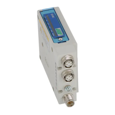
Side view of the Gateway unit
EX510-GDN1 (DeviceNet™ compliant)
Display Contents
Indicator light condition
PWR(V) The output power supply voltage is supplied as specified.
The output power supply voltage is not supplied as specified.
Light is turned on.
Light is turned off.
PWR When the input and the power for the Gateway is being supplied.
When the input and the power for the Gateway is not being supplied.
Light is turned on.
Light is turned off.
MNS
When the power supply is OFF, off-line, or checking the MAC ID duplication.
When I/O connection is on stand by. (On-line state)
I/O connection installation is completed. (On-line state)
I/O connection, time-out (communication irregularity in light degrees)
MAC ID duplication error, or BUS OFF error (communication error in
serious conditions)
Light is turned off.
Green light blinks.
Green light is
turned on.
Red light blinks.
Red light is turned
on.
COM
A to D
When COM A to D are receiving data.
When COM A to D are not receiving data.
Light is turned on.∗
Light is turned off.
∗ Input unit (Input device) is connected and will illuminate when communication is working properly.
GW System, 4 Branches Series EX510
Address setting
Number of
input settings
Number of
output settings
Communication
speed setting
HOLD/CLR setting
HW/SW setting
DC-DC
converter
(insulated)
Communication
part
Insulation circuit
(Photo-coupler)
CAN
transceiver
DC-DC
converter
(not insulated)
(Brown)
Power supply
for the input and
for the control unit
of the Gateway
Power supply
for output
Input/Output total 128 points
16 inputs
16 inputs
16 inputs
16 inputs
16 outputs
16 outputs
16 outputs
16 outputs
Input/Output total 64 points
16 inputs
16 inputs
16 inputs
16 inputs
Input/Output total 80 points
16 inputs
16 inputs
16 inputs
16 inputs
8 outputs
8 outputs
Input/Output total 80 points
16 inputs
16 inputs
16 inputs
16 inputs 16 outputs
Input/Output total 96 points
16 inputs
16 inputs
16 inputs
16 inputs
8 outputs
8 outputs
8 outputs
8 outputs
Input/Output total 96 points
16 inputs
16 inputs
16 inputs
16 inputs
16 outputs
16 outputs
Internal circuit
Input: 16 inputs 4-branch settings
Output: 16 outputs 4-branch settings
Input: 16 inputs 4-branch settings
Output: Unused settings
Input: 16 inputs 4-branch settings
Output: 8 outputs 2-branch settings
(at the time of shipping)
Input Output Input Output Input Output
Input: 16 inputs 4-branch settings
Output: 16 outputs 1-branch setting
Input: 16 inputs 4-branch settings
Output: 8 outputs 4-branch settings
Input: 16 inputs 4-branch settings
Output: 16 outputs 2-branch settings
Input Output Input Output Input Output
2133

