1. Preliminary note
1.1 Symbols used
►Instructions
> Reaction, result
[…] Designation of keys, buttons or indications
→Cross-reference
Important note, Non-compliance can result in malfunction or interference.
Information
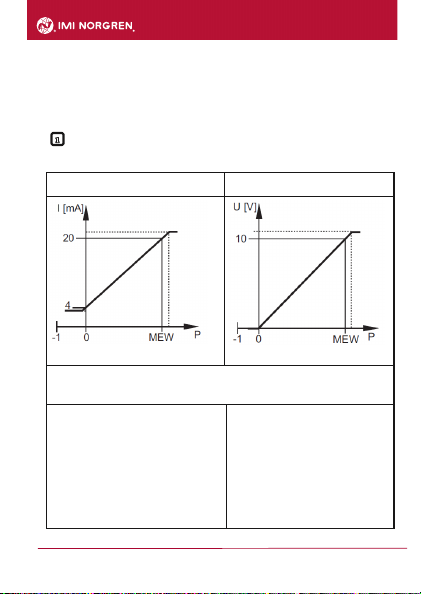
Supplementary note
2. Safety instructions
Please read this document prior to set-up of the unit. Ensure that the product is suitable for your
application without any restrictions.
If the operating instructions or the technical data are not adhered to, personal injury and/or
damage to property can occur.
Check the compatibility of the product materials with the media to be measured in all
applications.
Correct condition of the device for the operating time can only be guaranteed if the device is
only used for media to which the wetted materials are sufficiently resistant → 3.1 Applications.
If the devices are used in gas applications with pressures > 25 bar the notes in chapter 3.1 for
devices with the marking *), must be absolutely observed.
The responsibility whether the measurement device is suitable for the respective application
lies with the operator. The manufacturer assumes no liability for consequences of misuse
by the operator. Improper installation and use of the devices result in a loss of the warranty
claims.