IMP -600 Series User manual

IM
P
Series User
’
s Manua
l
1
IMP Series User’s Manual
600 / 670
1.0 Introduction------------------------------3
2.0 Getting started-------------------------4
3.0 Features of the IMP------------------5
4.0 Computer Operation------------------8
5.0 Hardware installation------------14
5.1 Illustration for IMP-600--------14
5.2 Illustration for IMP-670--------20
6.0 Software installation-------------28
7.0 Maintenance-----------------------------28
8.0 Problem solving----------------------30
9.0 SKD Accessory Kits--------------32
IMP Series 600 / 670
Index
Copyright ® 2004 All Right Reserved

IM
P
Series User
’
s Manua
l
2
Specification of
IMP
Series
Model No. IMP-600 IMP-670
Motherboard SBC + PBP ATX
SBC + PBP
Slot 8 7, 10, 12
Drive Bay 2 x 5.25"(open)
1 x 3.5"(open) 2 x 5.25"(open)
2 x 3.5"(open)
Color Black
LCD 14.1"
14.1" LCD, 150 nits brightness,
30,000 hrs of backlight life
15.1" & 15.4"
250 nits brightness,
50,000 hrs of backlight life
17”
280 nits brightness,
30,000 hrs of backlight life
Resolution 1024 x 768 1024 x 768, 1280 x1024,
D/C
ATI M3 chipset AGP card with 16MB
(with special backplane)
ATI M6 chipset AGP card with 64MB
(with special backplane)
ATI M6 D/C with 64MB Video RAM
ATI M3 chipset AGP card with 16MB
ATI M6 chipset AGP card with 64MB
Analog-to-digital conversion board
ATI M6 D/C with 64MB Video RAM
Keyboard / Mouse 108 keys, multi-languages/touchpad
Case Size 15.75"x12"x11.31" (400 x305 x 287mm) 17.75"x10.25"x14.4"(451x260x366 mm)
Power Supply Auto Sensing Active PFC PS/2 350 Watt Full range PS/2 400W with Active PFC
SKD Weight 15.9 kg (35 lbs) 17 kg (37 lbs)
Speaker Built-in amplified speaker
Amplified board output: 2 x 6 Watt Stereo
Speaker output: 1/2 Watt
Carrying Case Padded carrying case with wheels
Card Stabilize
Bars 1
Cooling Fan 2 x 60 x 60 x 25 mm 1 x 80 x 80 x 25 mm
Case Metal chassis-flame
Environmental Specification
Oper. Temp. 0°C-50°C
Relative Lum. 20-80% (non-condensing)
Shock
(operating, all
axes) 15g
Vibration
(operating, all
axes) 1.25g @ 10-100Hz
Compliance CE & FCC Class B Compliant, UL, CCIB

IM
P
Series User
’
s Manua
l
3
Version: 2004.2
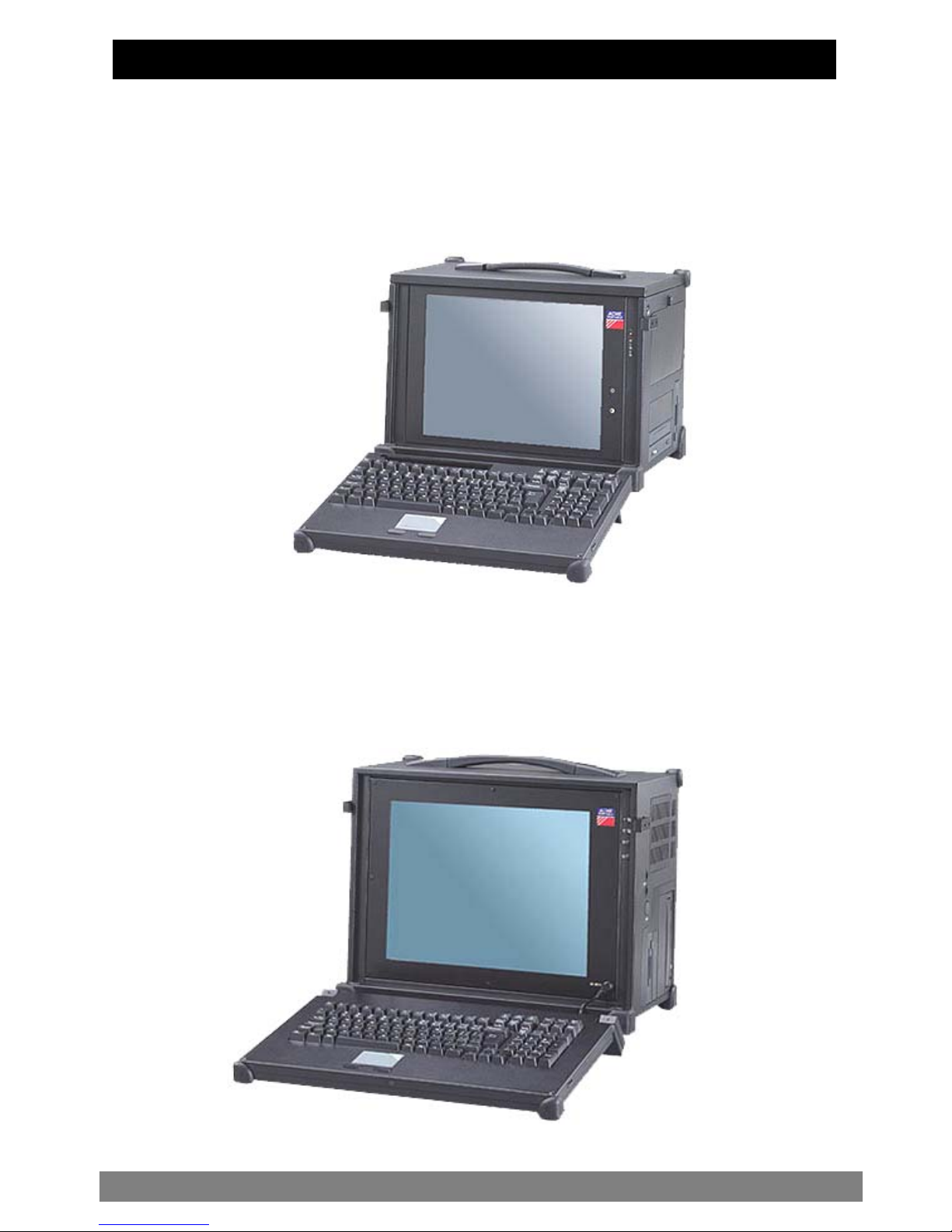
IMP Series Portables:
zHeavy duty & powerful rugged designed portable
zOffer 7-8 slots expansion capability to accommodate a standard
ATX size or SBC motherboard.
zHigh performance processing power.
zXGA (1024*768)TFT LCD Screen (from 14.1”-to 15.4”) steel frame
zThe new RJ-45 cabling style.
zMetal frame construction.
The IMP is a heavy-duty rugged industrial portable computing solution.
And it is highly compatible across a broad range of hardware,
software and operating systems. It has more computing power than
that of most desktops, and traditional portable computers. Its full size
add-in slots, Pentium 4 processing power, and a XGA resolution TFT
color display make it a high performance field solution. The IMP series
portables comply with FCC class B Part 15 and CE Mark. It’s an
unpredictably powerful choice for workstation or server.
You can find IMP in industrial environment serving you with high
performance computer bus analysis & telecommunication testing,
multi-protocol network analysis, PLC programming, real time
automatic industrial application and much more. It is designed to
function with your needs in mind.
1.0 Introduction

IM
P
Series User
’
s Manua
l
4
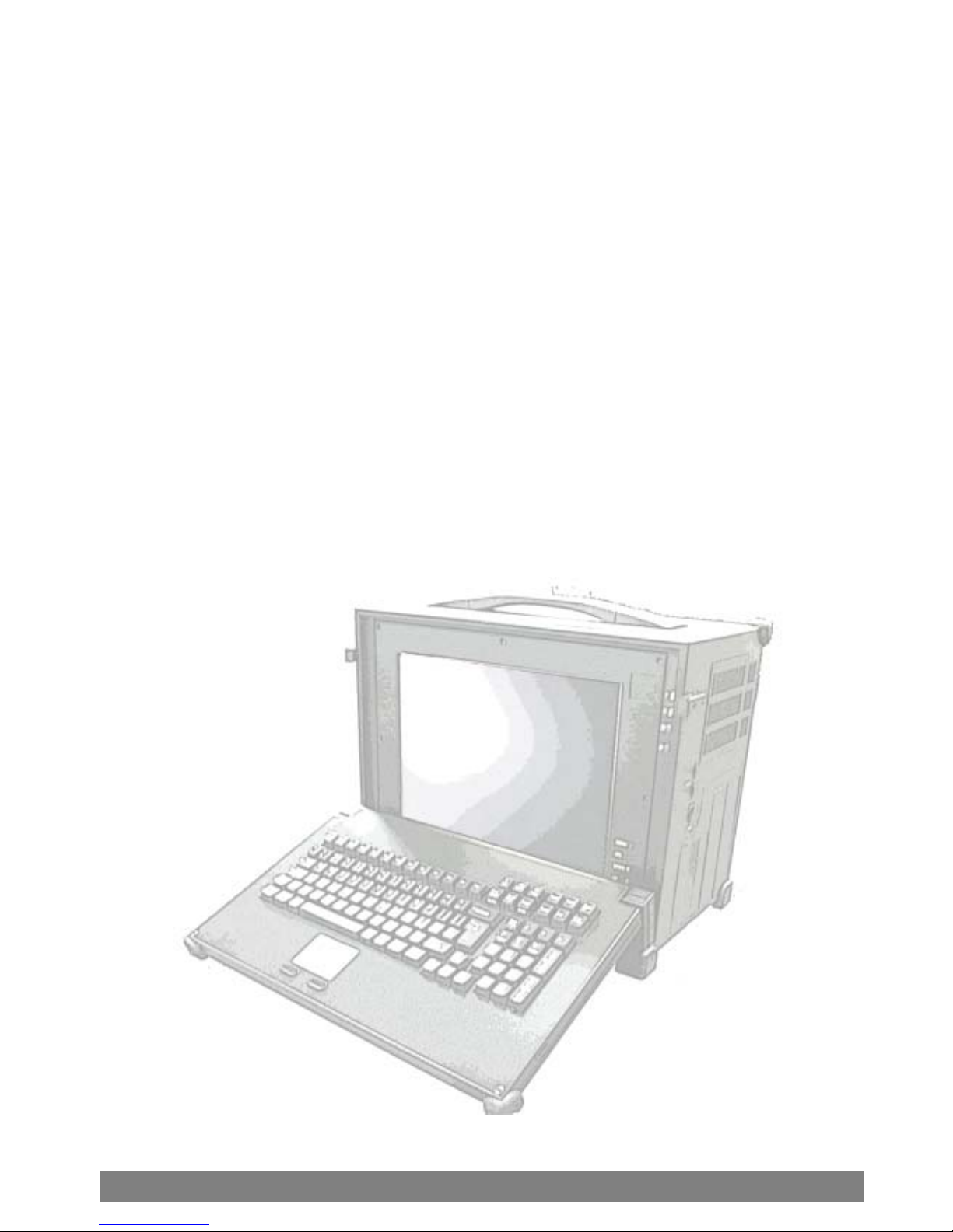
2.0 Getting Started
The IMP is a well design compact portable computing machine that is
both nimble as well as rugged. It will serve your needs for both
expansion as well as performance. An important aspect of the IMP is
the concept of standardizations, which means all components that
you can find off the shelf or proprietary designed will fit into the IMP. If
the peripheral is designed according to industry standard for
interconnectivity then it will fit. With that in mind, we will layout and
identify each of the component. In this section you can find each
component of the IMP with respect to its purpose and usage.
IMP 600
IMP 670
2.0 Getting Started
IM
P
Series User
’
s Manua
l
5
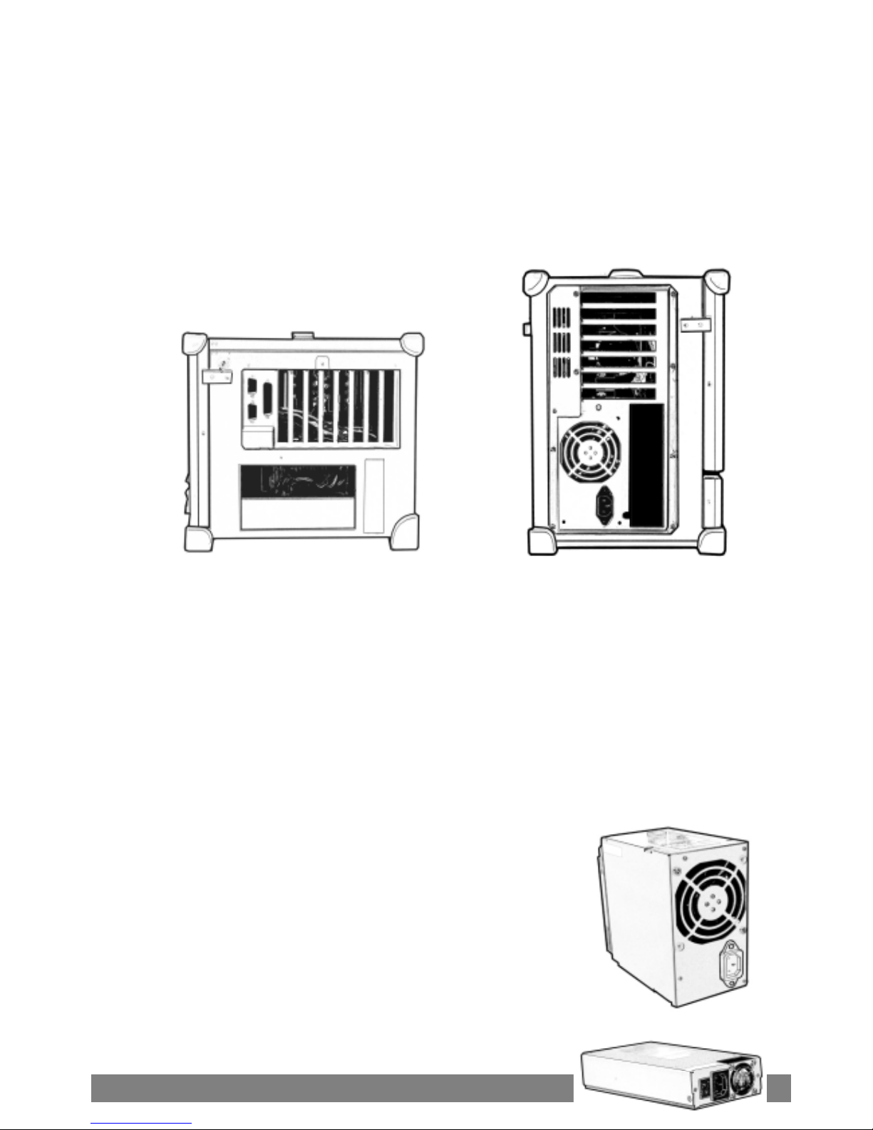
Drive Bays:
IMP 600 –with 2 x 5.25” open bays, 1x 3.5” open bays
IMP 670 – with 2 x 5.25” open bays, 2 x 3.5” open bays,
3.0 Feature of the IMP series serser
Features of the

IM
P
Series User
’
s Manua
l
6
Keyboard:
108-key keyboard is integrated with the portable allow closing
against the portable for both connivance and protection in
transportation.
Keyboard Cable:
The keyboard cable connects to the keyboard internally with
cable jack on other end for insertion into the portable lower right
hand corner; allow easy access and removal of the keyboard.
LED Status Indicator:
The green LED indicates power on, the red LED indicates hard disk
drive access.
Display:
Integrated TFT Active Matrix LCD provides XGA color display with
resolution of 1024*768 or 1280*1024 (for 14” & 15”).
Speaker:
Integrated two speakers built-in allow media audio play back
without having to outsource attachment. Speaker has volume
control for different environment usage(IMP 670).
Drive Bay:
The IMP 600 come standard with 2×5.25”size drives bays, and 1×3.5
size drive bays. IMP 670 come standard with 2×5.25”size drives bays,
and 2×3.5 size drive bay
Power Switch:
The power switch to turn on the computer is located on the right
side.
Fan:
Located inside the chassis, these fans will help draw out and push
in cool air to alleviate excessive heat built-up for components
inside the portable allowing worry free operation.
Filters:
Filters located on both sides of the portable help block out dust
and particle from entering the machine.
IM
P
Series User
’
s Manua
l
7
Expansion Slots:
Opening to provide access to the I/O ports on the installed add-in
cards.
Expansion slot Cover:
The slot cover covers the I/O opening for protection of vital
equipment inside, it serves to detour object from entering as well
as cooling (drilled opening).
Handle:
Large handle provide convenient transportation of the portable
with comfort and ease.
Keyboard Release Buttons:
These buttons when depressed will release the locking mechanism
to detach the keyboard from the main portable chassis.

IM
P
Series User
’
s Manua
l
8
4.1 Keyboard and Touch pad:
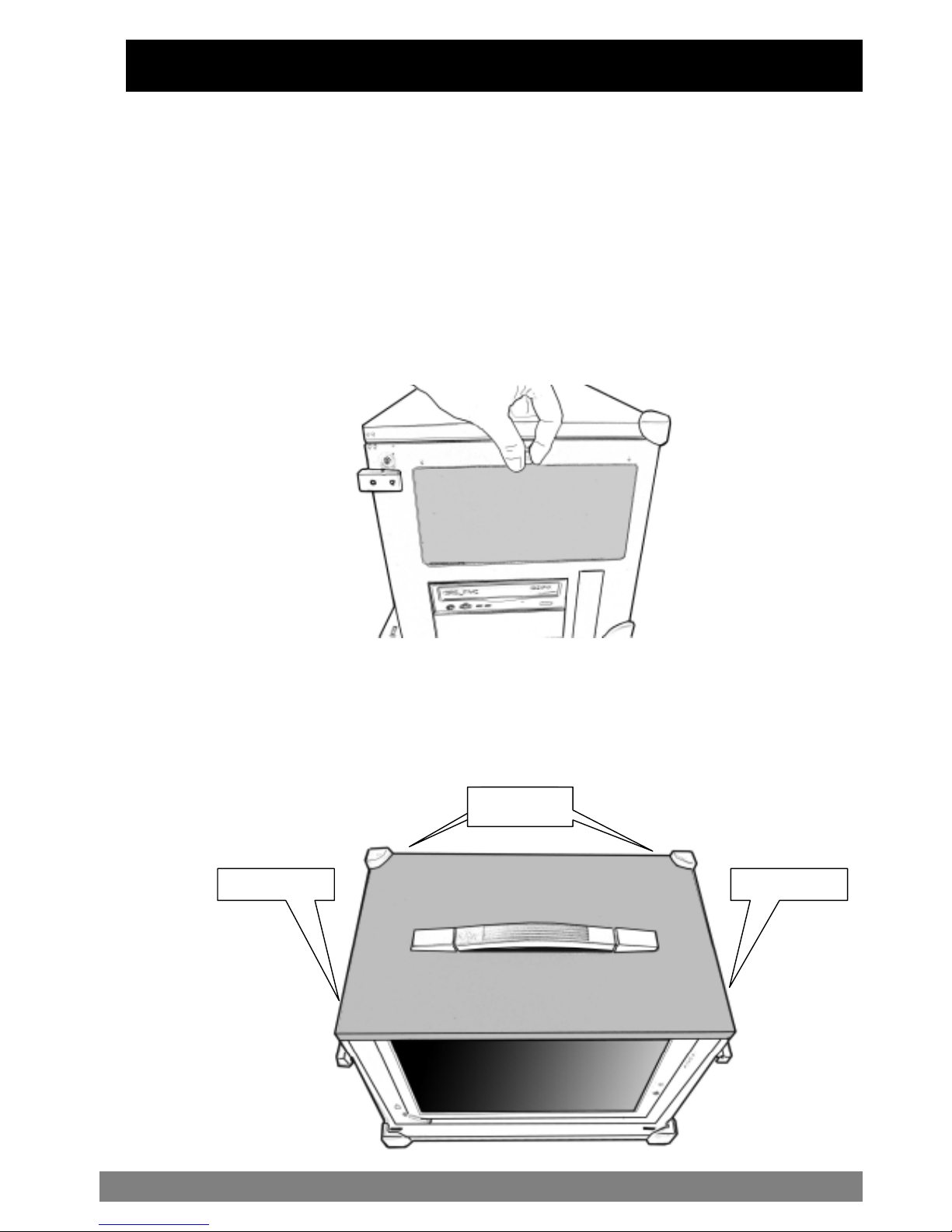
How to release
There are two release buttons
located on the top-left and top-right
of the keyboard. When depressed,
the keyboard is disengage from the
portable and will release the
keyboard structure. There are also
two mounting leg located at the
bottom of the keyboard that are
inserted into the portable for fitting
and stability, in which case you can
start lifting the keyboard upward.
The keyboard now can then be
removed for usage.
How to close keyboard
Closing the keyboard back onto the portable
follows the same procedure as opening, in a
reverse manner. It is noted that the keyboard
cable should be put back into its proper
lodging location. Make sure the two locking
mechanism are properly secure after it is put
back.
What to look for
The keyboard cable is located
on the top portion of the
keyboard; it is a coil cable with
a RJ45 connector at the end.
The jack should now be
attached to the portable (at
the lower right hand corner) to
be operational.
4.0 Computer operation
Features of the IMP
Press to release
Push
Here

IM
P
Series User
’
s Manua
l
9
K/B usage
Keyboard is the main medium for inputting data into the system. The
keyboard of the IMP series portables contains both a keyboard and
a touch pad. Keyboard is a 108-keys Windows ready keyboard with
power function and shortcut keys.
Keyboard position
You may want to adjust the keyboard angle by folding the top
portion of the keyboard or just taking off the main case.
TOUCHPAD operation
TOUCHPAD surface can be use to move
the cursor in the GUI environment by
placing and moving your finger. The two
buttons located below the touch pad
act as same as the mouse left/right
button. Or you may wish to tap on the
touch pad to indicate a left click.
IM
P
Series User
’
s Manua
l
10
4.2 Side Panel:
The side panel is located behind the plastic protection cover that can
be removed by pushing the clip. Depending on the system board and
your add-on cards, you may also have other ports such as Ethernet port,
and Audio ports. When in use, side panel can also be stored in a slot
located on the back cover
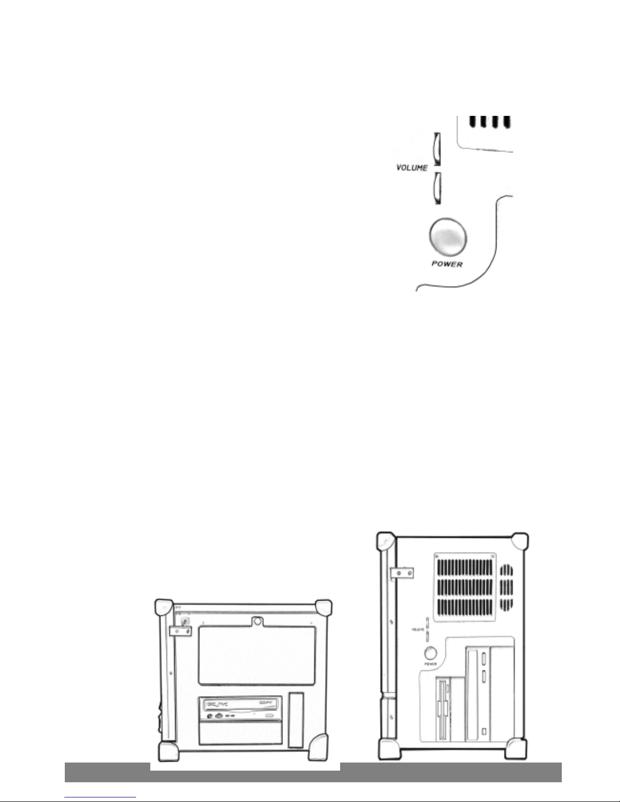
4.4 Power switch and plug:
The power receptacle is located on the right side of the machine near
the bottom. The three-prong power plug is supplied. Depending on
your Power supply type, you may find a main power switch located
next to the power receptacle and the position of the switch is of the
following: O=Off, I=On. This is the main power, to power up the system,
user still require to power on the machine at the front of the portable,
labeled Power. If your power supply does not have a main switch, user
will control power on/off using the power switch located in the front.
4.5 Power supply(PS/2)
This kind of power supply is supported in IMP 600 /
670 series.
It’s also Active PFC Full-Range, 400W output.
4.55 Power supply(1U):
This kind of power supply is supported only in
IMP 600 IMP 670

IM
P
Series User
’
s Manua
l
11
Option Order.
It’s auto-sensing full range with Active PFC, 250W output.
4.6 Hooking up external monitor:
The external CRT monitor / Projector can be hooked up via the side
panel VGA (15pin) port while the system is off. The CRT/Projector will
provide the cable to be inserted into this port. When connected, the
display should come on if the machine is powered on. The signal is
standard with the internal viewing resolution and the default setting is
simultaneous display both on portable’s LCD and CRT. To change the
output mode (Simultaneous/LCD only/CRT only), please refer to your
VGA setting.
4.6 Audio:
The audio of the system does require user to install a sound card.
The built-in internal amplified speakers provide a phono stereo
plug that will fit into the output port of the sound card.
IMP 600 IMP 670
Audio Area
IM
P
Series User
’
s Manua
l
12
4.6 Volume adjustment:
There are two volume adjustments on the
side panel.
Each volume adjustment may adjust
right or left sound performance by any
situation if possible.
4.7 CD-ROM & FDD Drive:
CD-ROM is important in that many of the applications available
today are store on the CD due to their larger storage capacity.
CD is read-only media (a CDR or CDRW are medium that are for
user creation of data on CD medium) and is pre-loaded with data.
You may open the CD-ROM drive door by pushing the eject
button located on the door of the drive. During access to the CD-
ROM, the light on the CD door will light up. Floppy disk drive is
essential as they are still an important medium for transferring data
before systems. Floppy disks are available in all computer stores
and are ready for usage in most case if pre-formatted.
IMP 600 IMP 670

IM
P
Series User
’
s Manua
l
13
4.8 Bottom Holders:
The bottom holders may support the whole frame up higher
position, it may provide better angle for operating.
4.9 VGA
Based on your model you may have either:
1. 16MB ATIM3, 2x AGP (with special backplane )
2. 64MB ATIM6, 4x AGP(with special backplane)
3.A/DConversionBoard
4. On-board system VGA
5. 64MB ATI M6 D/C Video Ram
Please refer to your VGA user’s manual for details
IMP 600 IMP 670
IM
P
Series User
’
s Manua
l
14
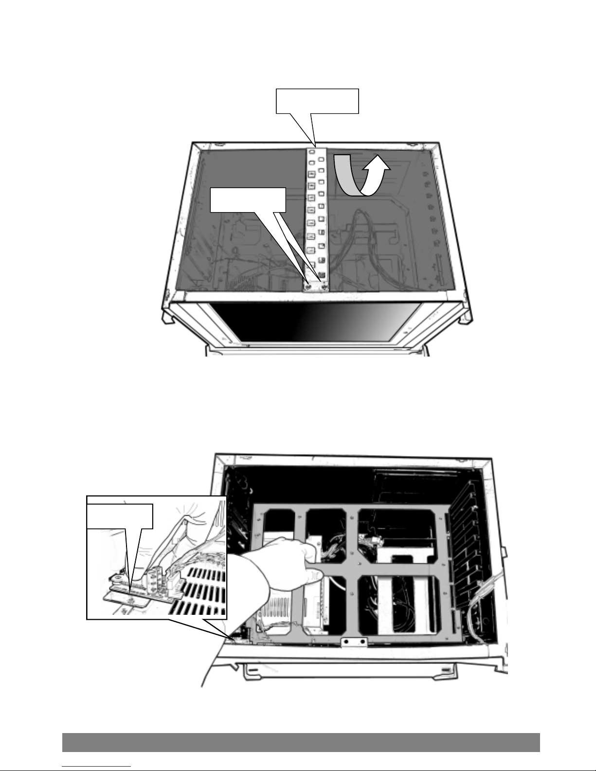
Before you attempt to open the IMP-600 and do any hardware
installation, make sure you have the proper knowledge of
installation and compatibility feature of any upgrade. And
understand the concept of electrostatic damage that can occur
during handling of sensitive electronic equipments, proper
precaution should be taken before proceeding.
1. Remove the side panel---------
2. Open back cover-----------------
5.1 Hardware Installation for IMP-600
F
Off
Unscrew
Unscrew
Unscrew
IM
P
Series User
’
s Manua
l
15
3.Remove stabilizer bars ------
4.Remove the inner chassis-----
*Please remove the sound adjust board before taking off the inner chassis..
Screw
Unscrew
Slide Out
Unscrew
IM
P
Series User
’
s Manua
l
16
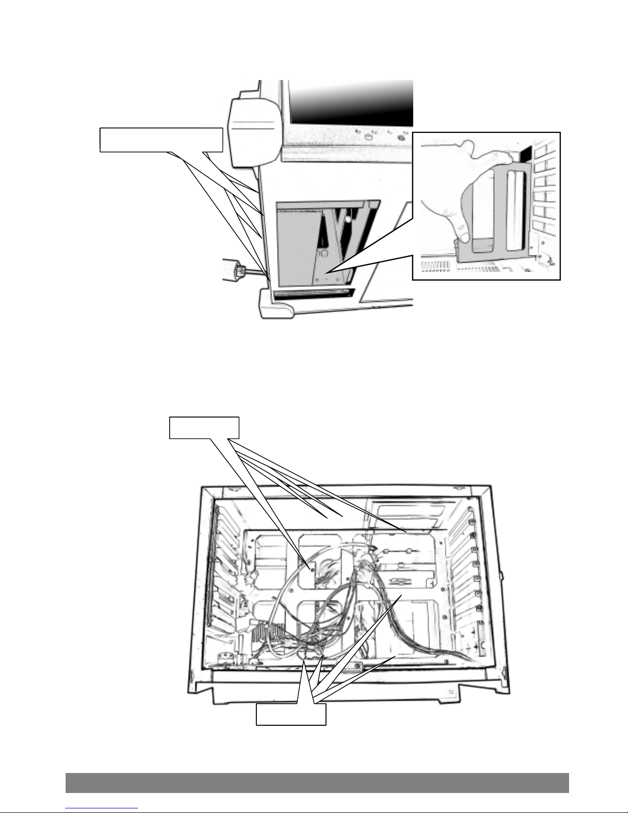
5.Remove drive bay housing----
6.Insert system board mounting
standoff--------
StandoffStandoffStandoffStandoff
StandoffStandofStandofStandoff
Bottom Screw x 4

IM
P
Series User
’
s Manua
l
17
*Please refer to your system board manual for detail references.
7. Install system board
with CPU and RAM-------
*Please refer to your system board manual for detail references.
8. Connect keyboard and touchpad
cables--------
※Please refer to your system board manual for detail references.
9. Connect power, LED, and
speaker wires---------------
※Please refer to System Board Manual for actual Location.
10.Install VGA card &
LCD ON/OFF wire---
※Please refer to your model’s removal process for reinstallation
Back Plane
RAM
CPU

IM
P
Series User
’
s Manua
l
18
11. Install HDD into
Drive bay housing-----
12. Install CDROM into
drive bay housing---
FDD Drive
HDD

IM
P
Series User
’
s Manua
l
19
Off
Reinsert
Reinsert
Reinsert
13. Connect IDE and
power cables------
14. Reinsert stabilizer bars----
15. Close back cover---------------
VGA card wire
LCD on/off wire
Reinsert
Slide

IM
P
Series User
’
s Manua
l
20
Before you attempt to open the IMP-600 and do any hardware
installation, make sure you have the proper knowledge of
installation and compatibility feature of any upgrade. And
understand the concept of electrostatic damage that can occur
during handling of sensitive electronic equipments, proper
precaution should be taken before proceeding.
1. Remove the side panel---------
2. Open back cover-----------------
※The screws are well-designed that won’t be departed from
the back cover
5.2 Hardware Installation for IMP-670
F
This manual suits for next models
1
Table of contents
Popular Desktop manuals by other brands


Fujitsu
Fujitsu CELSIUS C620 datasheet

Lenovo
Lenovo ThinkCentre M71e Guida per l'utente

Dell
Dell OptiPlex 9020 Technical guidebook

DMP Electronics
DMP Electronics EBOX-335xDX3 Series user guide

HP
HP Xw6200 - Workstation - 2 GB RAM installation instructions

Tek Panel
Tek Panel Tek Panel UHR 560 Specifications