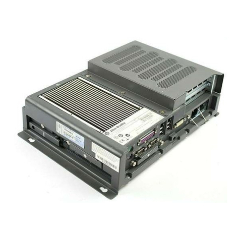
Rockwell Automation Allen-Bradley H Series User manual

Installation Instructions
Original Instructions
Industrial Computers for Hazardous Locations
Series H
Catalog Numbers
6181X-12A2SW71DC, 6181X-00N2SW71DC, 6181X-12A2SWX1DC,
6181X-00N2SWX1DC, 6181X-12P2SWX1DC
Topic Page
Summary of Changes 2
Installation Precautions 2
Hazardous Locations 4
Hot Surfaces 6
Restricted Access Location 6
Computer Options 6
Operating Systems 7
Before You Begin 7
Parts List 8
Installation Guidelines 8
Mounting Clearance Requirements 10
Computer Dimensions 11
Tools for Computer Installation 13
Install the Computer 13
Hardware Features 16
Connect Power 17
Connect to a Network 18
Accessories and Replacement Parts 19
Voltage Precautions 19
Electrostatic Discharge Precautions 19
Preconfiguration 20
Post-configuration 20
Tools for Component Replacement 20
Remove the Cover 21
Reinstall the Cover 21
Load a CompactFlash Card 21
Install an Add-in Card 23
Replace or Add Memory Modules 25
Real-time Clock (RTC) Battery 26
Ship or Transport the Computer 26
Technical Specifications 27
Additional Resources 30

2Rockwell Automation Publication 6181X-IN002D-EN-P - February 2020
Industrial Computers for Hazardous Locations
Summary of Changes
This publication contains new and updated information as indicated in this table.
Installation Precautions
Read and follow these precautions before you install the computer.
Environment and Enclosure Information
Topic Page
Replaced IEC with IECEx Zone 2 (minimum) in the second bullet underneath ‘For all non-display models’. 5
Replaced IEC with IECEx Zone 2 (minimum) in the second bullet underneath ‘For all integrated display models’. 5
Replaced IEC with IECEx in the third bullet underneath ‘For all non-display models’. 5
Replaced 1200P with 1200XT in the model column of Computer Options table. 6
Added a second sentence of instructions to steps a and e. 24
Added the three numbered callouts to the figure with step e. 24
Replaced em dash with 900 mA in USB ports row for Cat. No. 6181X-12P2SWX1DC. 29
ATTENTION: This equipment is intended for use in a Pollution Degree 2 industrial environment, in
overvoltage Category II applications (as defined in IEC 60664-1), at altitudes up to 2000 m
(6561 ft) without derating.
This equipment is considered Group 1, Class A industrial equipment according to IEC/CISPR 32 and
ABNT NBR IEC/CISPR 32. Without appropriate precautions, there can be potential difficulties with
electromagnetic compatibility in other environments due to conducted and radiated disturbance.
The equipment must be panel mounted or open-type, and installed in a tool-only accessible
enclosure that is suitable for the environment.
All 6181X-12 integrated display computers are shipped with a gasketed bezel to meet specified
ratings when mounted in a panel or enclosure with an equivalent rating. For more information
about these ratings, see Hazardous Locations on page 4.
In addition to this publication, see the following:
•Publication1770-4.1, Industrial AutomationWiring and Grounding Guidelines, for more
installation requirements
• ABNT NBR IEC 60529, NEMA 250, UL 50, and IEC 60529, as applicable to your region, for
explanations of the degrees of protection that are provided by enclosures

Rockwell Automation Publication 6181X-IN002D-EN-P - February 2020 3
Industrial Computers for Hazardous Locations
European Union Directive
This computer meets the European Union Directive requirements when installed within the
European Union or EEA regions and have the CE marking. A copy of the
declaration of the
conformity is available at rok.auto/certifications
.
To comply with EN 55024 and EN 55032, use the following for cable types.
Outdoor Installation
When you use a 6181X integrated display computer outdoors, consider the following to maximize
the field life of the front bezel and display:
• Select the proper enclosure
• Computer orientation
Ultraviolet (UV) and infrared radiation can reduce the field life of any electronic device. While the
materials used in the computer bezels provide long field life, that life can be improved by proper
installation. UV radiation from the sun causes all plastics to fade or yellow and become brittle over
time. Avoiding long-term exposure to direct sunlight helps protect the front of the computer from
direct exposure to UV radiation, and greatly increase its field life.
Rockwell Automation sells a sun shield (Cat. No. 6189X-SUNSHIELD) for the 6181X integrated
display computers. If you install a sun shield that closes over the display, the temperature between the
sun shield and the display cannot exceed the maximum temperature of the display, which is 55 °C
(131 °F). Adequately ventilate all sun shields to help prevent excess heat rise on the computer display.
Use stirring fans or active cooling in high altitude and high ambient temperature locations to keep
the internal enclosure temperature below 70 °C (158 °F). Use a heater in installations where the
ambient temperature is below -20 °C (-4 °F).
If possible, avoid placing the computer on the south (north in the southern hemisphere) or west side
of the cabinet. This reduces the heat rise due to solar loading during the hottest part of the day.
Mount the computer vertically to minimize solar loading on the display. Do not mount the computer
in a sloped enclosure if it exposes the computer to direct sunlight.
ATTENTION: To comply with EN 55024 and EN 55032, the following applies to cable usage:
• USB cables must be less than 3 m (9.84 ft) long
• All I/O cables, except for Ethernet cables, must be used indoors
• All I/O cables, except for Ethernet cables, cannot exit the building at any point and cannot
directly connect to cables outside the building
Cable Type Required Attribute Cable Type Required Attribute
LAN Shielded or unshielded DVI Shielded
USB Shielded DP Shielded
Serial RS-232 Shielded DC power Unshielded
IMPORTANT The Rockwell Automation approved sun shield (Cat. No. 6189X-SUNSHIELD) must be used if
the computer is exposed to direct sunlight.

4Rockwell Automation Publication 6181X-IN002D-EN-P - February 2020
Industrial Computers for Hazardous Locations
Hazardous Locations
This equipment is suitable for these location categories.
IMPORTANT 6181X computers can only be used in non-hazardous locations in any Eurasian Conformity
region.
Computer
Model Cat. Nos. Region Rating Temperature Range
Non-display 6181X-
00N2SW71DC,
6181X-
00N2SWX1DC
United States Class IN Division 2, Groups A, B, C, DT4 -20 °C < Ta<70 °C
(-4 °F < Ta< 158 °F)
Class I Zone 2, IIC, T4
Canada Class I Division 2, Groups A, B, C, DT4
Class I Zone 2, IIC, T4
Europe (ATEX) II 3 G, Ex ec IIC T4 Gc,
DEMKO 19 ATEX 2274 X
Global/IECEx Ex ec IIC T4 Gc, IECEx UL 19.0091 X
INMETRO Ex ec IIC T4 Gc, UL-BR 19.1305 X
Display
(12 in.)
6181X-
12P2SWX1DC
United States Class I Division 2, Groups A, B, C, D T4
Class II Division 2, Groups F, GT6
Class III Division 1 T6
-20 °C < Ta<55 °C
(-4 °F < Ta< 131 °F)
(display side)
-20 °C < Ta<70 °C
(-4 °F < Ta< 158 °F)
(backside)
Class I Zone 2, IIC, T4
Class II Zone 22, IIIB, T70 °C
Canada Class I Division 2, Groups A, B, C, DT4
Class II Division 2, Groups F, GT6
Class III Division 1 T6
Class I Zone 2, IIC, T4
Class II Zone 22, IIIB, T70 °C
Europe (ATEX) II 3 GD, Ex ec IIC T4 Gc IP66,
Ex tc IIICT70 °C Dc IP66,
DEMKO 19 ATEX 2274 X
Global/IECEx Ex ec IIC T4 Gc IP66,
Ex tc IIICT70 °C Dc IP66,
IECEx UL 19.0091 X
INMETRO Ex ec IIC T4 Gc IP66,
Ex tc IIICT70 °C Dc IP66,
UL-BR 19.1305 X
Display
(12 in.)
6181X-
12A2SW71DC,
6181X-
12A2SWX1DC
United States Class I Division 2, Groups A, B, C, D T4 -20 °C < Ta<55 °C
(-4 °F < Ta< 131 °F)
(display side)
-20 °C < Ta<70 °C
(-4 °F < Ta< 158 °F)
(backside)
Class I Zone 2, IIC, T4
Canada Class I Division 2, Groups A, B, C, DT4
Class I Zone 2, IIC, T4
Europe (ATEX) II 3 GD, Ex nA nC IICT4 Gc IP66,
Ex tc IIICT135 °C Dc IP66, DEMKO
17 ATEX 1851 X
Global/IECEx Ex nA nC IIC T4 Gc IP66,
Ex tc IIICT135 °C Dc IP66,
IECEx UL 17.0024 X

Rockwell Automation Publication 6181X-IN002D-EN-P - February 2020 5
Industrial Computers for Hazardous Locations
The Following Conditions for Safe Use Apply in ATEX, IECEx, and INMETRO
For all non-display models (Cat. Nos. 6181X-00N2SW71DC and 6181X-00N2SWX1DC).
• The equipment shall only be used in an area of not more than Pollution Degree 2, as
defined in EN/IEC 60664-1, as applicable to your region.
• The equipment shall be installed in an INMETRO/ATEX/IECEx Zone 2 (minimum)
certified enclosure that provides a degree of protection not less than IP54, and is only
accessible by use of a tool.
• Transient protection shall be provided that is set at a level not exceeding 140% of the
peak rated voltage value at the supply terminals to the equipment.
• The non-display computers were evaluated for use with a PCI Express (PCIe) or PCI
add-in card.
• PCIe and PCI add-in cards must be rated Zone 2 ATEX/IECEx/INMETRO, T4
(maximum), 4 W (maximum), 90 °C (194 °F) (minimum) surrounding ambient
temperature.
• The internal enclosure ambient temperature range is -20…+70 °C (-4…+158 °F).
For all integrated display models (Cat. Nos. 6181X-12A2SW71DC, 6181X-12A2SWX1DC,
and 6181X-12P2SWX1DC).
• The equipment shall only be used in an area of not more than Pollution Degree 2, as
defined in EN/IEC 60664-1, as applicable to your region.
• For EPL Gc, the equipment shall be installed in an INMETRO/ATEX/IECEx Zone 2
(minimum) certified enclosure that provides a degree of protection not less than IP54,
and is only accessible by use of a tool.
• For EPL Dc, the equipment shall be installed in an INMETRO/ATEX/IECEx Zone 22
(minimum) certified enclosure that provides a degree of protection not less than IP64,
and is only accessible by use of a tool.
• Transient protection shall be provided that is set at a level not exceeding 140% of the
peak rated voltage value at the supply terminals to the equipment.
• The ambient temperature (external to enclosure) range is -20…+55 °C (-4…+131 °F),
and that of the internal enclosure ambient temperature is -20…+70 °C (-4…+158 °F).
• The integrated display computers with a resistive touch screen (Cat. Nos.
6181X-12A2SW71DC and 6181X-12A2SWX1DC) were evaluated for use with a PCI
Express (PCIe) add-in card.
• The integrated display computer with a PCAP touch screen (Cat. No. 6181X-
12P2SWX1DC) was evaluated for use with a PCIe or PCI add-in card.
• PCIe and PCI add-in cards must be rated Zone 2 ATEX/IECEx/INMETRO, T4
(max), 4 W (max), 90 °C (194 °F) (min) surrounding ambient temperature.
• To maintain the IP66 rating of the equipment, it shall be mounted in an enclosure with
an equivalent IP rating.
• To minimize risk from electrostatic discharge, only clean the display with a damp cloth.
6Rockwell Automation Publication 6181X-IN002D-EN-P - February 2020
Industrial Computers for Hazardous Locations
Conditions for Safe Use in North American Hazardous Locations
The following statements apply to when the computer is used in a North American hazardous
location.
Hot Surfaces
Restricted Access Location
Verify that restricted access locations for the equipment meet these conditions:
• Access is gained only by service personnel or by users who have been instructed on the
reasons for restrictions to a location and about any precautions to be taken.
• Access is by using a tool, a lock and key, or other means of security controlled by the
authority responsible for the location.
Computer Options
This table summarizes the options that are available for industrial computers for hazardous
locations. A comparative summary of features for the computers is in Technical Specifications on
page 27.
WARNING: Explosion Hazard
• Do not connect or disconnect the device or any connected peripheral equipment unless
power has been switched off and the area is known to be non-hazardous.
• Peripheral equipment must be suitable for the location where it is used.
• In the U.S., all wiring must be in accordance with Class I, Division 2 wiring methods of Article 501
of the National Electrical Code, and in accordance with the authority having jurisdiction.
• In Canada, all wiring must be in accordance with Section 18-1J2 of the Canadian Electrical
Code, and in accordance with the authority having jurisdiction.
• In final applications, properly connect these devices to ground by using the ground terminal
screw on the computer chassis.
• PCIe and PCI add-in cards must be rated
Class I, Division 2,
T4 (max), 4W (max), 90 °C (194 °F)
(min) surrounding ambient temperature.
IMPORTANT The Rockwell Automation approved sun shield (Cat. No. 6189X-SUNSHIELD) must be used if
the computer is exposed to direct sunlight.
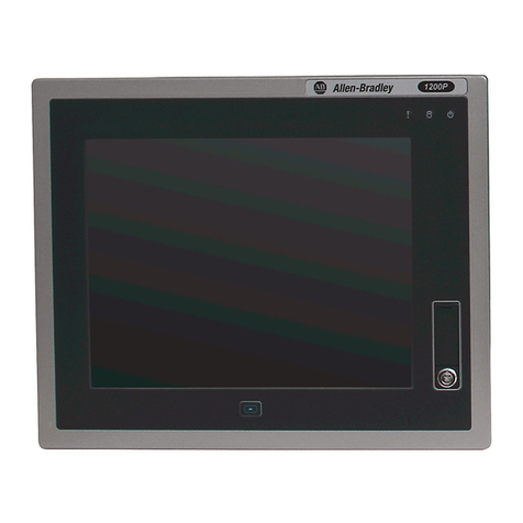
Cat. No. Model Series Display Size Touch Screen Windows OS
6181X-00N2SW71DC NDM H —7 Professional 64-bit SP1
6181X-12A2SW71DC 1200XT 12.1 in. Resistive
6181X-00N2SWX1DC NDM —10 IoT Enterprise 64-bit
6181X-12A2SWX1DC 1200XT 12.1 in. Resistive
6181X-12P2SWX1DC PCAP(1)
(1) PCAP touch screen supports multi-touch operation.

Rockwell Automation Publication 6181X-IN002D-EN-P - February 2020 7
Industrial Computers for Hazardous Locations
This table shows what accessories are available for industrial computers for hazardous locations.
You can view a current list of accessories and replacement parts at https://ab.rockwell
automation.com/Computers/Hazardous-Location-Display-Computers#selection.
Operating Systems
The following Microsoft®-licensed operating systems are available:
• Windows® 7 Professional (64 bit), SP1
• Windows 10 Internet of Things (IoT) Enterprise (64 bit)
These solid-state drives are customized to accommodate their unique properties as follows:
•Nopagingfile
• System restore is disabled by default
To obtain a copy of a factory system image, access the Rockwell Automation Product
Compatibility and Download Center (PCDC) at
https://compatibility.rockwellautomation.com/Pages/home.aspx.
Before You Begin
Before you unpack the computer, inspect the shipping carton for damage. If damage is visible,
immediately contact the shipper and request assistance. Otherwise, continue to unpack.
Keep the original packing material in case you must return the computer for repair or transport it
to another location. Use both inner and outer packing cartons to provide adequate protection for
a computer that is returned for service.
Cat. No. Description
6189X-MCLPS Replacement mounting clips (10)
6189X-16GDDR3 16 GB DDR3 RAM memory for extended temperature
6189V-CFSSD8GB CompactFlash card, 8 GB single-level cell (SLC) solid-state drive (SSD)
6189V-CFSSD16GB CompactFlash card, 16 GB SLC SSD
6189X-128GBSSD 128 GB multi-level cell (MLC) SSD
6189X-256GBSSD 256 GB MLC SSD
6189X-PCIRISER PCIe x1 to PCI riser card(1)
(1) This card can only be used in Cat. Nos. 6181X-00N2SW71DC, 6181X-00N2SWX1DC, and 6181X-12P2SWX1DC.
6189X-SUNSHIELD Sun shield

8Rockwell Automation Publication 6181X-IN002D-EN-P - February 2020
Industrial Computers for Hazardous Locations
Parts List
The computers ship with these items.
Installation Guidelines
Follow these guidelines to make sure that your computer provides service with excellent reliability:
• The installation site must have sufficient power.
• Verify that the DC power wires meet these requirements.
• In dry environments, static charges can build up easily. Proper grounding of the computer
helps to reduce static discharges, which can cause shock and damage electronic components.
• The enclosure must allow sufficient space around air inlets and outlets to provide the
circulation necessary for cooling. See Mounting Clearance Requirements on page 10 for
further information. Never allow air passages to become obstructed.
Item Description
Hardware • Screws with grommets to mount non-display computers
• Clips to mount integrated display computers
Documents • This publication
• 6181P and 6181X Industrial Computers CutoutTemplate, publication 6181P-DS002(1)
• Production test report
(1) Shipped only with integrated display computers.
Attribute Requirement
Wire material Stranded copper, insulation 90 °C (194 °F) min
Wire gauge
• To connect to DC input terminal block
• To connect to earth ground
• 0.823…2.08 mm2(18…14 AWG)
•1.5mm
2(16 AWG) or larger(1)
(1) Use a ground wire with an insulation color allowed by local inspection authority.
Wire temperature rating, min 76 °C (169 °F)
Torque values
• For DC input terminal block screws
• For functional ground screw
• 1.36 N•m (12 lb•in)
• 1.47 N•m (13 lb•in)

Rockwell Automation Publication 6181X-IN002D-EN-P - February 2020 9
Industrial Computers for Hazardous Locations
•Theambient air temperature must not exceed the maximum operating temperature in
Environmental Specifications on page 29. Consider a user-supplied fan, heat exchanger,
or air conditioner for heat that is generated by other devices in the enclosure.
• The relative humidity of the ambient air must not exceed limits in Environmental
Specifications on page 29 and must avoid condensation.
• The enclosure or cover must always remain in place during operation. The cover provides
protection against high voltages inside the computer and inhibits radio frequency
emissions that can interfere with other equipment.
• When mounted, the computer cannot be tilted from vertical.
TIP Hot air rises. The temperature at the top of the enclosure is often higher than the
temperature in other parts of the enclosure, which is likely if air is not circulating.
IMPORTANT The computer can operate at a range of extremes. If you continuously operate the
computer at its highest rated temperature, then the life span of any electronic
device is shortened, which includes the touch screen and LCD panel.
55 °C (131 °F) max
outside enclosure
70 °C (158 °F) max
inside enclosure
Restricted Access
Location
Non-display ComputerIntegrated display computer
70 °C (158 °F) max
inside enclosure
Integrated Display Computers Non-display Computer
Top
Bottom (I/O ports)
Top
Bottom (I/O ports)
Vertical
(0° tilt)
Top
Bottom (I/O ports)
Vertical
(0° tilt)
PCAP Touch Screen Resistive Touch Screen

10 Rockwell Automation Publication 6181X-IN002D-EN-P - February 2020
Industrial Computers for Hazardous Locations
Mounting Clearance Requirements
Minimum Clearances (display model shown)
IMPORTANT Because of self-heating, do not operate the computer in an enclosure by using the minimum
clearances unless adequate ventilation or other methods are used to lower the temperature
within the enclosure.
Allow enough clearance to install or remove peripheral components, such as internal drives.
The minimum required enclosure size (HxWxD) is 403 x 497 x 154 mm (15.87 x 19.57 x 6.06 in.).
Right and left are based on facing a computer from inside an enclosure.
Item Description Value
1 Top 50 mm (2 in.)
2 Right (for airflow) 50 mm (2 in.)
3Rear 50mm(2in.)
4 Left (for airflow and drive access) 127 mm (5 in.)
5 Bottom (for I/O port access and ventilation) 102 mm (4 in.)
4
5
3
12
Airflow Direction

Rockwell Automation Publication 6181X-IN002D-EN-P - February 2020 11
Industrial Computers for Hazardous Locations
Computer Dimensions
Review computer dimensions to estimate the clearance necessary for computer installation.
Non-display Computers
1.6
(0.06)
190.5
(7.5)
83.4
(3.28)
57.5
(2.26)
335.3 (13.2)
320.2 (12.61)
238.2
(9.37)
16.4
(0.65)
16.4
(0.65)
87.1
(3.43)
87.1
(3.43)
87.1
(3.43)
251
(9.88)
Dimensions are in mm (in.)

12 Rockwell Automation Publication 6181X-IN002D-EN-P - February 2020
Industrial Computers for Hazardous Locations
Integrated Display Computers
115 (4.53)
349 (13.74)
101.3 (4)
75.4 (2.97)
14.5 (0.57)
320 (12.6)
251
(9.88)
279
(10.98)
115 (4.53)
Dimensions are in mm (in.)
349 (13.74)
101.3 (4)
75.4 (2.97)
14.5 (0.57)
251
(9.88)
279
(10.98)
Resistive Touch Screen
PCAP Touch Screen

Rockwell Automation Publication 6181X-IN002D-EN-P - February 2020 13
Industrial Computers for Hazardous Locations
Tools for Computer Installation
These tools are required for computer installation:
• #2 cross-head screwdriver
• Panel cut out tools (for panel mounting)
• Drill motor, drill bit, and M4 screw tap (for wall mounting)
• Anti-static wriststrap
Install the Computer
The computers support these mounting options:
• Panel mount (integrated display computer models)
• Wall mount (non-display computer models)
Panel Mounting Guidelines
Observe these guidelines when you install the computer in a panel:
• Remove all electrical power from the panel before making the cutout.
• Verify that there is adequate space behind the panel. For specific information, see
Mounting Clearance Requirements on page 10.
• Cut supporting panels to specifications before installation. Take precautions so metal
cuttings do not enter components that are already installed in the panel.
Supporting panels must be at least 16 gauge for proper sealing against water and dust,
and to provide proper support. The supplied mounting hardware accommodates panel
thickness between 16…6 gauge or 1.6…6 mm (0.064…0.24 in.). Make sure that the area
around the panel cutout is clear.
Panel Cut Out Dimensions
The 6181P and 6181X Industrial Computers Cut Out Template, publication 6181P-DS002, is
shipped with all 6181X integrated display computers.
The integrated display computers must be mounted to meet these panel cut out dimensions.
ATTENTION: Failure to follow these guidelines can result in personal injury or damage
to the panel components.
Cat. Nos. Cut Out Dimensions (H x W), Approx
6181X-12A2SW71DC,
6181X-12A2SWX1DC,
6181X-12P2SWX1DC
254 x 324 mm (10 x 12.76 in.)

14 Rockwell Automation Publication 6181X-IN002D-EN-P - February 2020
Industrial Computers for Hazardous Locations
Mount the Integrated Display Computer in a Panel
Use the supplied clips to secure the integrated display computer to the panel.
Follow these steps to mount the integrated display computer in a panel.
1. Remove power from the panel.
2. Verify that the panel surface around the area to be cut is clean and free of debris.
3. Cut an opening in the panel by using the appropriate panel cutout dimensions.
4. Make sure that the sealing gasket is properly positioned on the computer.
This gasket forms a compression-type seal. Do not use sealing compounds.
5. Place the computer in the panel cutout.
6. Slide the clips into the holes on the top, bottom, and sides of the computer.
7. Hand-tighten the clips around the bezel by following this tightening sequence.
8. Repeat this process at least three times until the clips are hand-tight and the gasket is
compressed uniformly against the panel.
9. Tighten the clips to a torque of 1.35 N•m (12 lb•in) by following the torque sequence,
making sure not to overtighten.
Cat. Nos. Clips (qty.) Cat. No. Description
6181X-12A2SW71DC, 10 6189X-MCLPS Replacement mounting clips (10)
6181X-12A2SWX1DC,
6181X-12P2SWX1DC
ATTENTION:
Take precautions so metal cuttings do not enter components that are already
installed in the panel to avoid personal injury or damage to the panel components.
5
4
3
6
9110
82
7
Hand-tighten and Torque Sequence

Rockwell Automation Publication 6181X-IN002D-EN-P - February 2020 15
Industrial Computers for Hazardous Locations
10. Repeat this process at least three times until the clips are properly torqued, making sure
that the gasket is compressed uniformly against the panel.
Mount the Non-display Computer on a Wall
Use the four supplied screws to secure the non-display computer to a metal wall, such as a steel
panel in an enclosure or equipment room.
Follow these steps to mount a non-display computer.
1. Verify that the power is disconnected.
2. After you decide where to mount the computer, drill holes in the wall to accommodate
the four supplied M4 panhead screws.
The illustration shows the mounting hole locations with dimensions in mm (in.).
3. Attach two of the supplied screws with grommets to positions 1 and 2.
4. Mount the computer to the wall.
5. Attach the remaining two supplied screws with grommets to positions 3and 4.
6. Tighten to a torque that is appropriate for the screw and wall material.
The recommended torque in steel is 1.13…1.36 N•m (10…12 lb•in).
ATTENTION: Tighten the clips to the specified torque to provide a proper seal and to
help prevent damage to the computer. Rockwell Automation assumes no responsibility
for water or chemical damage to the computer or other equipment within the enclosure
because of improper installation.
IMPORTANT Do not mount the non-display computer on a horizontal surface.
335.3 (13.2)
190.5
(7.5)
43
21

16 Rockwell Automation Publication 6181X-IN002D-EN-P - February 2020
Industrial Computers for Hazardous Locations
Hardware Features
This section shows the hardware features of the industrial computers for hazardous locations.
An integrated display computer with a resistive touch screen is shown for illustrative purposes.
Item Component Item Component
1 LCD panel (only on display models) 8 Power switch
2 128 GB MLC SSD 9 DC input terminal block
3 Rear cover 10 Functional ground screw
4 CompactFlash (CF) Type II card slot(1)
(1) The USB ports and the bottom CF card slot are hot swappable but only in non-hazardous locations. For more information about proper use of these
ports, refer to Outdoor Installation on page 3.
11 4 USB 3.0 ports(1)
5 Serial COM ports (RS-232), 2 12 DVI-D port
6 1 Gb LAN ports (RJ45), 2 13 DisplayPort
7 PCIe riser slot cover
1
3
2
45 6 7
13 11 10 98
12

Rockwell Automation Publication 6181X-IN002D-EN-P - February 2020 17
Industrial Computers for Hazardous Locations
Connect Power
Display and non-display computers have a DC input terminal block for connection to an
18…32V DC power source.
Operate the computer in an industrial or control room environment, which uses some form of
power isolation from the public low-voltage mains.
The DC power option supports operation from safety extra low voltage (SELV) power source.
The power supply is internally protected against reverse polarity.
Follow these steps to connect the computer to a DC power source.
1. Turn off the main power switch or breaker.
2. Verify that the DC power wires meet the requirements in the table in Installation
Guidelines on page 8.
3. Secure the DC power wires to the terminal block by tightening the terminal block screws
to the torque value listed in the table in Installation Guidelines on page 8.
ATTENTION: When you connect power to the computer for the first time, these actions occur:
• The default BIOS setting automatically starts the computer after it is plugged into a power
source.
• You must read and accept an End-User Setup procedure for computers with aWindows
operating system.
Do not disconnect power from the system until after the Windows Setup procedure is completed.
Disconnecting power during this procedure can result in a corrupted system image.
ATTENTION: Supply the computer circuit with its own disconnect. Use an uninterruptible power
source (UPS) to help protect against unexpected power failure or power surges.
Always shut down theWindows operating system before disconnecting power to the computer to
minimize performance degradation and operating system failures.
ATTENTION: Use a SELV isolated and ungrounded power supply as input power to the computer.
This power source provides protection so that under normal and single fault conditions, the
voltage between the conductors and Functional Earth/Protective Earth does not exceed a safe
value.
IMPORTANT A functional ground connection is required for EMC compliance.
-V +V

18 Rockwell Automation Publication 6181X-IN002D-EN-P - February 2020
Industrial Computers for Hazardous Locations
4. Secure the ground wire to the functional ground screw by using a ring connector.
Tighten the functional ground screw to the computer at the torque value listed in the
table in Installation Guidelines on page 8.
5. Apply 18…32V DC power to the computer.
Connect to a Network
The computers have two 1 Gb LAN ports. The computers connect to an Ethernet network by
using CAT5 or better twisted-pair Ethernet cable with RJ45 connectors.
IMPORTANT When using the functional ground screw, connect the computer to earth ground by
using the wire gauge listed in the table in Installation Guidelines on page 8.
WARNING: When you connect a LAN cable, verify that the cable is fully inserted in the LAN port
and the latch is engaged. Failure to do so could result in an electric arc that can cause an explosion
in a hazardous location.
IMPORTANT To help prevent performance degradation of Ethernet communication, do not subject the
computer or cables to extreme radiation or conducted high-frequency noise.
In industrial environments, proper cable routing and power conditioning are required for
Ethernet communication. Rockwell Automation recommends that you route all Ethernet
cable through dedicated metal conduits. For improved performance reliability, install ferrite
bead filters at the cable ends.
Ring
Connector
Functional
Ground Screw

Rockwell Automation Publication 6181X-IN002D-EN-P - February 2020 19
Industrial Computers for Hazardous Locations
Accessories and Replacement Parts
You can view a current list of accessories and replacement parts at https://ab.rockwell
automation.com/Computers/Hazardous-Location-Display-Computers#selection.
Review the specifications of a new component before you install it to verify that it is compatible
with the computer. Record the model and serial number, and any other pertinent information of
new components for future reference.
Voltage Precautions
The computers contain line voltages. Disconnect all power to the computer before you install or
remove components.
Electrostatic Discharge Precautions
Follow these precautions:
• Keep electrostatic-sensitive parts in their containers until they arrive at the designated
static-free work area.
• Cover the designated work area with approved static-dissipating material:
– Use an anti-static wriststrap that is connected to the work surface.
– Use properly grounded tools and equipment.
• Keep the designated work area free of nonconductive materials, such as ordinary plastic
assembly-aids and foam packing.
• Avoid contact with pins, leads, or circuitry.
• Always hold components with a printed circuit board (PCB) by its edges and place it
with the assembly side down.
• To minimize risk from electrostatic discharge, only clean displays with a damp cloth.
IMPORTANT We recommend that you use only Allen-Bradley® approved accessories and replacement
parts.
SHOCK HAZARD: Disconnect all power to the computer before you remove components.
Failure to disconnect power can result in severe electric shock to an individual or electrostatic
discharge (ESD) damage to the computer and components.
ATTENTION: Electrostatic discharge (ESD) can damage static-sensitive devices or microcircuitry.
• Disconnect all power before you work on the computer as detailed in Voltage Precautions on
page 19.
• Observe proper packaging and grounding techniques to help prevent damage.

20 Rockwell Automation Publication 6181X-IN002D-EN-P - February 2020
Industrial Computers for Hazardous Locations
Preconfiguration
Follow these steps before you remove the cover or replace a hardware component.
1. Shut down the computer and all peripherals that are connected to it.
2. To avoid exposure to high energy levels, disconnect all cables from power outlets.
If necessary, label each cable to expedite reassembly.
3. To avoid exposure to a shock hazard from ring voltages, disconnect telecommunication
cables.
Post-configuration
Follow these steps after you install or remove a hardware component.
1. Make sure that all components are installed according to instructions.
2. Make sure that no tools or loose parts are left inside the computer.
3. Reinstall any expansion boards, peripherals, and system cables that were previously
removed.
4. Reinstall the cover according to the instructions on page 21.
5. Reconnect all external cables and power to the computer.
6. Press the power switch to start the computer.
Tools for Component Replacement
The following tools are required for component replacement:
• #2 cross-head screwdriver
• Anti-static wriststrap
IMPORTANT When you install hardware or you perform maintenance procedures that require access to
internal components, we recommend that you first back up all computer data to avoid loss.
ATTENTION: Make sure to read and understand all installation and removal procedures before
you begin to configure the computer hardware.
This manual suits for next models
6
Table of contents
Other Rockwell Automation Desktop manuals

Rockwell Automation
Rockwell Automation Allen-Bradley VersaView 6180W-12KPXPH User manual

Rockwell Automation
Rockwell Automation VersaView 5400 User manual

Rockwell Automation
Rockwell Automation Allen-Bradley 6181X-12A2SW71DC, Allen-Bradley 6181X-00N2SW71DC, Allen-Bradley 6181X-12A2SWX1DC, Allen-Bradley... User manual

Rockwell Automation
Rockwell Automation Allen-Bradley VersaView 6300B User manual

Rockwell Automation
Rockwell Automation Allen-Bradley 6181P-2PXP User manual

Rockwell Automation
Rockwell Automation 6181P User manual