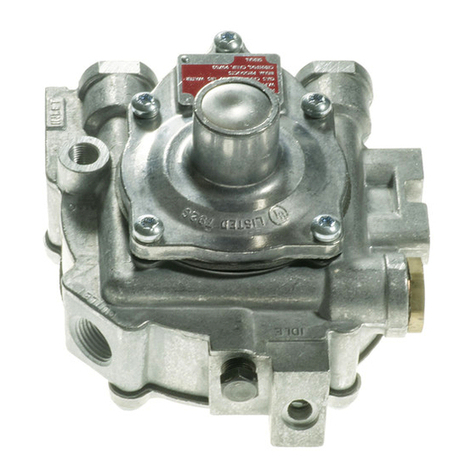
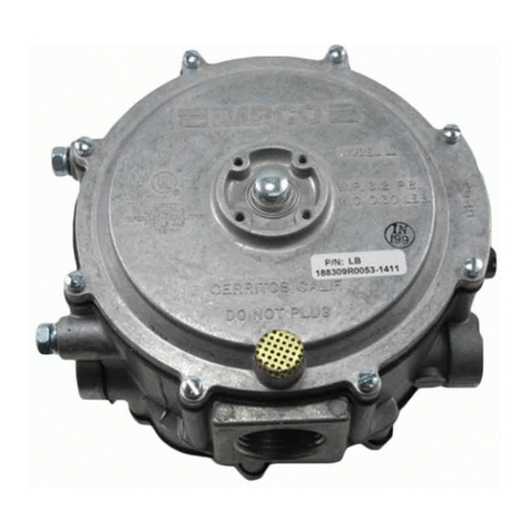
Impco Genius Max User manual

December, 2014 IMPCO Technologies Inc. PPI-131 REV. A
3030 South Susan St. Page 1 of 16
Santa Ana, CA 92704
www.impcotechnologies.com
3030 S Susan Street, Santa Ana, CA 92704
Ph: +1 714 656 1200 Fax: +1 714 656 1400
Genius Max
REGULATOR REPAIR KIT INSTRUCTIONS
NOTE: Only die cast Genius Max
regulators manufactured late 2014 and
after can be repaired using the repair kits
listed below. Repairable units are
identified by the IMPCO logo and the
words Genius Max cast into the top
cover. All Genius Max regulators black
in color are not serviceable using these
repair kits.
Important: Any maintenance, service or
repair should be performed by trained and
experienced service technicians. Proper
tools and equipment should be used to
prevent injury to the servicing technician,
property or system components. Service
repairs should always be performed in a
safe environment and the technician should
always wear protective clothing to prevent
injury.
The IMPCO PPI-131 repair kit instructions
will provide the technician information to
successfully repair the Genius Max
regulator. Always inspect the major casting
pieces for damage, corrosion or cracks
before attempting a service repair. Be sure
the repair kit part number you are using is
correct for the regulator being serviced.
Prior to disassembly, inspect the body for
any signs of impact, cracks or other damage
to the body that might render the regulator
non-repairable.
Do not use Teflon tape to seal any fuel fittings.
Failure to follow this warning may cause the
regulator to leak internally, that may cause serious
injury and/or property damage.
Genius Max Regulator Repair Kit Part Numbers
Part Number
Description
RK-GMAX-001
Repair Kit, Genius Max
RK-GMAX-002
Repair Kit, Genius Max (Includes the Pressure Relief Device or valve)

PPI-131 REV. A IMPCO Technologies Inc December, 2014
3030 South Susan St. Page 2 of 16
Santa Ana, CA 92704
www.impcotechnologies.com
3030 S Susan Street, Santa Ana, CA 92704
Ph: +1 714 656 1200 Fax: +1 714 656 1400
Genius Max Regulator (Internal Fittings)
See following page for External Fittings
ITEM # RK-GMAX
DESCRIPTION
1 -
Body, Lower, Genius Max Dc
2 -001, -002
Gasket, Bottom, Genius Max
3 -
Body, Center, Genius Max
4 -
Screw, Set M4x0.7x54mm
5 -001, -002
Gasket, Top, Genius Max
6
Body, Upper, Genius Max
7 -001, -002
Seat, Viton (80 Shore)
8 -
Holder, Seat, Genius Max
9 -
Lever, Genius Max
10 -
Pin, Steel, Ø3 X 30mm
11 -
Screw, Cross Head Pan M4 X 8mm (2)
12 -
Shaft, Link, Genius Max
13 -001, -002
O-Ring, Viton, Metric 1mm CS X 4mm ID
14 -
Plate, Diaphragm Bottom
15 -001, -002
Diaphragm, Genius Max
16 -
Plate, Top, Genius Max
17 -
Washer, Conical Spring, 5mm
18 -
Nut, Locking, M5
19 -
Spring, L48.5mm, O.D. 33.3mm, K11.8N/mm
20 -
Plate, Spring Load Adjustment
21 -
Screw, Adjustment
22 -001, -002
O-Ring, Fluorocarbon 0.070 Cs X 0.301 I.D. (2)1
23 -
Tube, Outlet, Genius Max
24 -
Screw, Shcs Pthd m6 x 40 Class 8.8 Zinc (6)
25 -002
Valve Subasm, Genius Max (includes 22 & 27)
26 -001, -002
Ring, Retaining, Internal
27 -
O-Ring, Fluorocarbon 0.070 Cs X 0.426 I.D.

December, 2014 IMPCO Technologies Inc. PPI-131 REV. A
3030 South Susan St. Page 3 of 16
Santa Ana, CA 92704
www.impcotechnologies.com
3030 S Susan Street, Santa Ana, CA 92704
Ph: +1 714 656 1200 Fax: +1 714 656 1400
Genius Max Regulator (External Fittings)
Genius Max Regulator (GMX-53400-001 shown)
ITEM # RK-GMAX
DESCRIPTION
Genius Max Sub Assy w/M12 x 1 fitting
Genius Max Sub Assy w/1/4" x 18 NPT
Fitting, LPG Inlet, Genius Max (M12 X 1)
Fitting, LPG Inlet, Genius Max (1/4"-18 Npt)
33 -
Filter, Inlet, Genius Max
34 -001, -002
O-Ring, Fluorocarbon (Fluorel/Viton) 0.07 Cs X .551 I.D.
35 -
Fitting, M8 X 1, Genius Max
36 -001, -002
O-Ring, Fluorocarbon (Fluorel/Viton) 0.070 Cs X .208 I.D.
37 -
Fitting, 12mm Hose BRC Standard
38 -
Fitting, Straight
39 -001, -002
O-Ring, Fluorocarbon (Fluorel/Viton) 0.070 Cs X .614 I.D.
40 -001, -002
Pin, Retainer (2)
32
31
-
-

PPI-131 REV. A IMPCO Technologies Inc December, 2014
3030 South Susan St. Page 4 of 16
Santa Ana, CA 92704
www.impcotechnologies.com
3030 S Susan Street, Santa Ana, CA 92704
Ph: +1 714 656 1200 Fax: +1 714 656 1400
Genius Max Repair Kit Components.
Item#
Description
RK-GMAX-001
RK-GMAX-002
2
Gasket, Bottom, Genius Max
1
1
5
Gasket, Top, Genius Max
1
1
7
Seat, Viton (80 Shore)
1
1
13
O-Ring, Viton, Metric 1mm Cs X 4mm ID
1
1
15
Diaphragm, Genius Max
1
1
22
O-Ring, Fluorocarbon 0.070 Cs X 0.301 I.D.
2
1
25
Valve Subasm, Genius Max
-
1
26
Ring, Retaining, Internal
1
1
27
O-Ring, Fluorocarbon 0.070 Cs X 0.426 I.D.
1
-
34
O-Ring, Fluorocarbon (Fluorel/Viton) 0.07 Cs X .551 I.D.
1
1
36
O-Ring, Fluorocarbon (Fluorel/Viton) 0.070 Cs X .208 I.D.
1
1
39
O-Ring, Fluorocarbon (Fluorel/Viton) 0.070 Cs X .614 I.D.
6
6
40
Pin, Retainer (Part Number P1-30559)
2
2
Not Shown
Repair Kit Instructions, PPI-131
1
1
Note that Valve Subassembly (25) is only included in RK-GMAX-002 which includes O-rings 22 and 27.

December, 2014 IMPCO Technologies Inc. PPI-131 REV. A
3030 South Susan St. Page 5 of 16
Santa Ana, CA 92704
www.impcotechnologies.com
3030 S Susan Street, Santa Ana, CA 92704
Ph: +1 714 656 1200 Fax: +1 714 656 1400
DISASSEMBLY INSTRUCTIONS
1. Remove the MAP hose Fitting (35).
2. Remove the Pins (40) retaining the port Fittings (38)
and remove from the Body (1). Remove O-rings (39)
from Fittings.
3. Using a 5mm Allen wrench, remove the six Screws (24)
from the top of the regulator and remove the upper
Body (6).
4. If the Body components stick together, the Center
Body (3) includes two tabs (as shown in the photo)
where a slotted screw driver can be inserted to pry to
the Body components apart.
NOTE: Do not use a screwdriver or other sharp
instrument at any location other than the tabs on the
center body. Sharp objects may scratch or damage the
sealing surfaces, causing the regulator to leak.
.

PPI-131 REV. A IMPCO Technologies Inc December, 2014
3030 South Susan St. Page 6 of 16
Santa Ana, CA 92704
www.impcotechnologies.com
3030 S Susan Street, Santa Ana, CA 92704
Ph: +1 714 656 1200 Fax: +1 714 656 1400
5. Remove the Nut (18) using an 8mm socket. Remove
the Washer (17) and Plate (16).
6. Lift the Body Center (3) from the Lower Body (1).
7. Remove the two screws (11) securing the fulcrum Pin
(10) and remove the Pin and Lever (9) complete with
Seat Holder (7 and 8).
8. Remove the Link Shaft (12) and its O-ring (13).
NOTE: Do not use any sharp objects that might
scratch the brass Link Shaft.

December, 2014 IMPCO Technologies Inc. PPI-131 REV. A
3030 South Susan St. Page 7 of 16
Santa Ana, CA 92704
www.impcotechnologies.com
3030 S Susan Street, Santa Ana, CA 92704
Ph: +1 714 656 1200 Fax: +1 714 656 1400
9. Remove the Gaskets (2 and 5) from the Center
Body (3).
NOTE: Do not use any sharp objects that might
scratch any of the sealing surfaces.
10. Press on the Allen Key hole in the center of the
label to push the Adjustment Screw (21) and
Spring Load Plate (20) through the Link Shaft hole.
11. Using retaining ring pliers, remove the Retaining
Ring (26) securing the Pressure Relief Device or
Valve (25).
12. Note the bottom of the brass Valve (25) inside the
channel of the Upper Body (6) and using a small
regular flat-blade screwdriver, gently press the top
of the blade until the Valve pops out the top of the
Upper Body.
NOTE: Use care and avoid scratching any surfaces.

PPI-131 REV. A IMPCO Technologies Inc December, 2014
3030 South Susan St. Page 8 of 16
Santa Ana, CA 92704
www.impcotechnologies.com
3030 S Susan Street, Santa Ana, CA 92704
Ph: +1 714 656 1200 Fax: +1 714 656 1400
13. RK-GMAX-001 Kit Only (this step is not required when
using RK-GMAX-002): Remove the O-rings (22 and
27) on the Valve (21).
NOTE: The Valve is a pre-set pressure relief device
and is not serviceable. Do not remove the label,
immerse in any fluid or cleaning solvent or attempt to
service the Valve.
14. Remove the LPG Inlet Fitting (32).
15. Remove the Seat (7) from the Lever (8 & 9) by
inserting a small blunt object through the hole from
behind. A ballpoint pen is shown in the picture.
16. Once all of the gaskets and O-rings have been
removed, thoroughly clean the body and metal
components using a solvent to remove any
deposits, varnish or contaminants.
NOTE: Do not use any solvent on the Valve (25) as it
may be rendered unusable.
NOTE: Do not use any type of mechanical tool to
scrape the sealing surfaces as they may cause the
regulator to leak.

December, 2014 IMPCO Technologies Inc. PPI-131 REV. A
3030 South Susan St. Page 9 of 16
Santa Ana, CA 92704
www.impcotechnologies.com
3030 S Susan Street, Santa Ana, CA 92704
Ph: +1 714 656 1200 Fax: +1 714 656 1400
REASSEMBLY OF REGULATOR
Carefully clean and inspect all metal parts, springs, levers, pivot pins and screws. Replace all parts
that are included in the repair kits.
Carefully clean the body casting and inspect all sealing surfaces. Wipe with a clean rag. Clear out the
inlet and outlet passages with compressed air. Be sure no foreign material remains in these passages.
17. Lightly lubricate with petroleum jelly or Vaseline
and place the O-ring (34) on the Fuel Inlet Fitting
(32).
18. Install the LPG fuel fitting (32). Torque to 18-22
Nm (13.3-16.2 ft-lbs.).
19. Press the Seat (7) into the Holder (8), installed on
the Lever (9).

PPI-131 REV. A IMPCO Technologies Inc December, 2014
3030 South Susan St. Page 10 of 16
Santa Ana, CA 92704
www.impcotechnologies.com
3030 S Susan Street, Santa Ana, CA 92704
Ph: +1 714 656 1200 Fax: +1 714 656 1400
20. Slide the O-ring (13) on the Link Shaft (13).
21. Place the Link Shaft (12) through the hole in the
Lever (9) and slide to the end of the slot in the
Lever. Slide the Pin (10) into the Lever, then
place the assembly into the Lower Body (1).
22. Secure the Pin (10) with two Screws (11) and
torque to 1.7-2.3 Nm (15-20 in-lbs.).
23. Lightly lubricate with petroleum jelly or Vaseline,
then place the Bottom Gasket (2) on the Center
Body (3). Press firmly into the grove, ensuring
the Gasket isn’t twisted and properly seated.

December, 2014 IMPCO Technologies Inc. PPI-131 REV. A
3030 South Susan St. Page 11 of 16
Santa Ana, CA 92704
www.impcotechnologies.com
3030 S Susan Street, Santa Ana, CA 92704
Ph: +1 714 656 1200 Fax: +1 714 656 1400
24. Lightly lubricate with petroleum jelly or Vaseline,
then place the Top Gasket (5) on the top of the
Center Body (3).
25. Place the Center Body (3) on the Lower Body (1)
inserting the Link Shaft (12) through the Center
Body.
26. Place the Bottom Diaphragm Plate (14)
downward (flat side up) over the threaded Link
Shaft (12)
27. Lightly lubricate the perimeter of the Diaphragm
(15) with petroleum jelly or Vaseline, then place
on top of the Center Body (3). Using your finger,
press on the perimeter of the Diaphragm to
ensure it properly seats into the Center body.
NOTE: The Diaphragm is positioned so the raised
outer ring or bag is up (as pictured).
Place the Plate (16) flat side down on top of the
Diaphragm. Place the Washer (17) concave side
downso its perimeter is in contact with the Plate.
Hand thread Nut (18) on Link Shaft (12).

PPI-131 REV. A IMPCO Technologies Inc December, 2014
3030 South Susan St. Page 12 of 16
Santa Ana, CA 92704
www.impcotechnologies.com
3030 S Susan Street, Santa Ana, CA 92704
Ph: +1 714 656 1200 Fax: +1 714 656 1400
28. Torque the Nut (18) to 1.35-1.65 Nm (12-14.5 in-
lbs.).
29. Place the Spring (19) on top of the Diaphragm
Plate (16).
30. Lubricate O-ring (22) with petroleum jelly or
Vaseline, and place on the Adjustment Screw
(21).
NOTE: There is no need to separate the Adjustment
Screw from the Plate (20).
31. Press the Plate (20) and Adjustment Screw (21)
assembly into the bottom of the Top Body (6) so
the Adjustment Screw fits flush with the top of the
Body.

December, 2014 IMPCO Technologies Inc. PPI-131 REV. A
3030 South Susan St. Page 13 of 16
Santa Ana, CA 92704
www.impcotechnologies.com
3030 S Susan Street, Santa Ana, CA 92704
Ph: +1 714 656 1200 Fax: +1 714 656 1400
32. Place the Top Body (6) on top of the Center (3)
and Lower Body (1) assembly. Press down to
compress the spring while lightly tightening the
Screws (24).
33. Torque each Screw (24) in a criss-cross pattern
in the order pictured to 7.4-8.6 Nm (5.5-6.3 ft-
lbs.).
34. Lubricate O-ring (36) with petroleum jelly or
Vaseline, and place on MAP Fitting (35). Thread
into the Top Body (6) and using a 10mm socket
wrench, torque to 2.55-3.45 Nm. (22.5-30.5 in-
lbs.).
35. Lubricate O-rings (22 and 27) with petroleum jelly
or Vaseline, and place on the Valve (25).
NOTE: When using repair kit RK-GMAX-002,
discard the old Valve and use the new one included
in the kit, complete with new O-rings.

PPI-131 REV. A IMPCO Technologies Inc December, 2014
3030 South Susan St. Page 14 of 16
Santa Ana, CA 92704
www.impcotechnologies.com
3030 S Susan Street, Santa Ana, CA 92704
Ph: +1 714 656 1200 Fax: +1 714 656 1400
35. Press in the Valve (25) until it seats below the rim
of the Top Body (6).
36. Secure the Valve (25) with the new Ring Clip (26)
using Ring clip pliers.
37. Lubricate O-rings (39) with petroleum jelly or
Vaseline, and place two on each of the Port
Fittings (38).
38. Insert the Coolant Fittings (38) into the ports on
the Lower Body (1) and secure with Retaining
Pins (40).

December, 2014 IMPCO Technologies Inc. PPI-131 REV. A
3030 South Susan St. Page 15 of 16
Santa Ana, CA 92704
www.impcotechnologies.com
3030 S Susan Street, Santa Ana, CA 92704
Ph: +1 714 656 1200 Fax: +1 714 656 1400
39. Insert the Fuel Outlet Fitting (37) into the port of
the Upper Body (6) and secure with Retaining
Clips (40) as pictured.
40. Install the Genius Max regulator in the vehicle and
turn on the fuel supply to pressurize the regulator.
Using soap and/or a commercial leak detector
solution, check for leaks, especially around the
Center Body (3). If no leaks are found, start the
engine, allow to idle and check for leaks again. If
leaks are found, the rebuild has failed and the
regulator must be replaced.
47. If no leaks are found, check the outlet pressure
using computer based diagnostic software to
read the fuel rail pressure sensor. Start the
engine and note the pressure. The pressure
should read 1.45-1.55 Bar (21.0-22.5.psi). If
not, the pressure can be adjusted using a 4mm
Allen key. Turn the Adjustment Screw (21)
clockwise to reduce pressure and counter-
clockwise to increase. Once the outlet pressure
has been set to 1.45-1.55 Bar (21.0-22.5 psi),
the regulator can be returned to service.

PPI-131 REV. A IMPCO Technologies Inc December, 2014
3030 South Susan St. Page 16 of 16
Santa Ana, CA 92704
www.impcotechnologies.com
3030 S Susan Street, Santa Ana, CA 92704
Ph: +1 714 656 1200 Fax: +1 714 656 1400
WARNING:
IMPROPER INSTALLATION OR USE OF THIS PRODUCT MAY CAUSE
SERIOUS INJURY, DEATH AND/OR PROPERTY DAMAGE
SERVICE TECHNICIANS AND USERS SHOULD CAREFULLY READ AND ABIDE BY THE PROVISIONS SET FORTH IN
NATIONAL FIRE PROTECTION ASSOCIATION PAMPHLET #37 FOR STATIONARY ENGINES, #52 FOR CNG VEHICULAR
FUEL SYSTEMS OR #58 FOR LPG SYSTEMS.
INSTALLERS LPG INSTALLATIONS IN THE UNITED STATES MUST BE DONE IN ACCORDANCE WITH FEDERAL, STATE
AND LOCAL LAWS AND NATIONAL FIRE PROTECTION ASSOCIATION PAMPHLET #58, STANDARD FOR STORAGE
AND HANDLING OF LIQUEFIED PETROLEUM GASES, TO THE EXTENT THESE STANDARDS ARE NOT IN VIOLATION
OF FEDERAL, STATE OR LOCAL LAW.
COUNTRIES OUTSIDE OF USA REFER TO THE GOVERNING AGENCIES OVERSEEING CNG AND PROPANE
APPLICATIONS.
CNG INSTALLATIONS IN THE UNITED STATES MUST BE DONE IN ACCORDANCE WITH FEDERAL, STATE AND LOCAL
LAW AND NATIONAL FIRE PROTECTION ASSOCIATION PAMPHLET #52, COMPRESSED NATURAL GAS (CNG)
VEHICULAR FUEL SYSTEMS, TO THE EXTENT THESE STANDARDS ARE NOT IN VIOLATION OF FEDERAL, STATE OR
LOCAL LAW.
LPG AND/OR NATURAL GAS INSTALLATIONS ON STATIONARY ENGINES MUST BE DONE IN ACCORDANCE WITH
FEDERAL, STATE AND LOCAL LAW AND NATIONAL FIRE PROTECTION ASSOCIATION PAMPHLET #37, STATIONARY
COMBUSTION ENGINES AND GAS TURBINE ENGINES, TO THE EXTENT THESE STANDARDS ARE NOT IN VIOLATION
WITH FEDERAL, STATE OR LOCAL LAW. FAILURE TO ABIDE BY THE ABOVE WILL VOID ANY IMPCO WARRANTY ON
THE PRODUCTS AND MAY CAUSE SERIOUS INJURY OR PROPERTY DAMAGE.
SERVICE TECHNICIANS DUE TO THE INHERENT DANGER OF GASEOUS FUELS, IMPCO PRODUCTS SHOULD NOT BE
INSTALLED OR USED BY PERSONS NOT KNOWLEDGEABLE OF THE HAZARDS ASSOCIATED WITH THE USE OF
GASEOUS FUELS. ANY MAINTENANCE, SERVICE OR REPAIR SHOULD BE PERFORMED BY TRAINED AND
EXPERIENCED SERVICE TECHNICIANS.
PROPER TOOLS AND EQUIPMENT PROPER TOOLS AND EQUIPMENT SHOULD BE USED TO PREVENT INJURY TO
THE SERVICING TECHNICIAN, PROPERTY OR SYSTEM COMPONENTS. SERVICE REPAIRS SHOULD ALWAYS BE
PERFORMED IN A SAFE ENVIRONMENT AND THE TECHNICIAN SHOULD ALWAYS WEAR PROTECTIVE CLOTHING TO
PREVENT INJURY.
INSPECT BEFORE USE ALWAYS INSPECT THE MAJOR CASTING PIECES FOR DAMAGE, CORROSION OR CRACKS
BEFORE ATTEMPTING A SERVICE REPAIR. BE SURE THE REPAIR KIT PART NUMBER YOU ARE USING IS CORRECT
FOR THE COMPONENT(S) BEING SERVICED.
NO TEFLON TAPE DO NOT USE TEFLON TAPE TO SEAL ANY FUEL FITTINGS. FAILURE TO FOLLOW THIS WARNING
MAY CAUSE THE REGULATOR TO LEAK INTERNALLY, POSSIBLY RESULTING IN SERIOUS INJURY, DEATH AND/OR
PROPERTY DAMAGE AND MAY VOID ANY WARRANTY COVERAGE.
Other Impco Controllers manuals
Popular Controllers manuals by other brands

norbar
norbar T-BOX 2 Operator's manual
AFRISO
AFRISO AVD 10 operating instructions

Mitsubishi Electric
Mitsubishi Electric SV13/22 Programming manual
Johnson Controls
Johnson Controls York 366-70488 Installation and Maintenance
Sullair
Sullair SUPERVISOR CONTROLLER user manual
Graham
Graham Vari Speed S1000 instruction manual
Tekmar
Tekmar Mixing Control 356 manual
Akerstroms
Akerstroms SESAM 800 RXM operating manual
Vexve
Vexve AM40 Instructions & user's manual
J.P. Instruments
J.P. Instruments EDM-730 pilot's guide
MidNite Solar
MidNite Solar The Kid quick start guide
Ewellix
Ewellix CAHB-2 Series Installation, operation and maintenance manual
